Information
Authors: C. Yakey, V. Nemkov, R. Goldstein, J. Jackowski
Location/Venue: ASM HTS 15 Detroit, MI
Topic: Coil Design Techniques
Abstract
With the use of good design practices, one can improve coil longevity and improve production quality. By eliminating failure points in the initial design, proper material selection, improved cooling and proper magnetic flux control, induction tooling life can be increased. Computer simulation has been proven to be an effective tool for predicting not only electromagnetic parameters of a designed system, but also heat patterns in a given part and in the induction coil itself. When a coil has magnetic flux controllers present, their influence may also be predicted by computer simulation. With an extensive library of published case histories in induction coil design and performance evaluations, we are confident with the use of these tools and proper coil geometries and implementation, production life and quality can be improved on most induction heat treating inductors. These design practices have been used by the authors for over 20 years with proven results. A case is examined of a CVJ stem hardening coil, in which the principles discussed can be applied to most other hardening coils.
Introduction
The quality of an induction coil is a major determinant of the cost to produce induction heat treated components. Oftentimes, the difference between a well designed and manufactured inductor and a poor performing inductor is not readily apparent. However, a high quality induction coil can lead to substantially lower component manufacturing costs and higher profitability for the induction heat treater. The additional costs of a poorly designed inductor include:
- Higher per component tooling costs
- Increased time for change
- Higher energy cost per component
- Increased cycle time
- Increased unplanned downtime
- More frequent part inspection
- More frequent scrap
There have been many papers published that describe the source of induction coil failures, good design practices and methods for increasing coil lifetime [1-‐6] and the authors encourage induction heat treaters to read these along with many other articles that exist on this topic. Some of the sources of induction coil failures include:
- Mechanical impact between the coil and part
- Arcing between different areas of the induction coil & part
- Coil component cracking/melting/burning due to overheating
- Coil component cracking/breaking/falling off/deformation due to mechanical vibration
With the proper design, coil manufacturing techniques and of course, preventative maintenance, inductor lifetime can be quite long and per component tooling costs negligible (even if the coil is much more expensive than a poorly built one). A Constant Velocity Joint (CVJ) stem hardening coil is examined to demonstrate how subtle changes can be made to inductor designs and/or manufacturing techniques that result in substantial improvement to coil lifetime and a dramatic reduction in the cost to produce induction heat treated components for the part supplier. The principles discussed can be applied to many other types of hardening coils.
CVJ Stem Coil Design Discussion
Automotive CVJ’s are a component that is frequently induction hardened in a captive heat treatment environment. The volumes tend to be quite high for these components, so the induction heating power densities are high to limit the cycle time. Due to this, lifetimes for some of these inductors can be low if they are not well designed.
For CVJ’s, an induction hardened layer is required in the stem fillet, shaft and spline. The most common induction coil style used for hardening this type of component is a single shot with quench in place. Magnetic flux controllers are usually applied to critical areas to increase heat concentration to meet the pattern requirements (Figure 1).
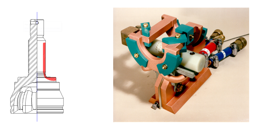
Figure 1: Typical CVJ heat treating pattern (left) and single shot coil (right)
The most common cause of failure for this type of induction coil is overheating of a section on the lower loop that drives heat into the fillet. This is especially true when frequency is low (below 15 kHz) and the fillet radius is small (less than 4 mm). The overheating typically occurs in the copper nose under the magnetic flux controller, or in the magnetic flux controller just on the nose adjacent to the shaft. The coil will typically fail by one of the following methods:
- Copper cracking in the overheated area due to thermal fatigue, which results in water spraying on the component or an arc to the part
- Melting of the lower loop due to the formation of a vapor barrier between cooling water and the copper
- Loss of pattern depth in the fillet due to concentrator overheating and property degradation.
The root cause of all of these failures (even the concentrator overheating) is high temperature of the copper in the nose of the inductor.
For this type of application (and other similar ones), there are some basic tips and pointers to help the life of this specific lower loop. We will start with something as basic as copper selection for the lower loop. Oxygen free copper, where available, is a better alloy to use for “loops” on inductors. Oxygen free copper has better thermal and electrical conductivity characteristics than stock 101 copper, and for the modest price increase it has been proven to be worth it. We can also make some changes to the physical design of the inductor to increase life cycles. Whenever possible, avoid using a square corner in the bore and adding a radius or chamfer to reduce the current load on that edge. This will prevent failure of this edge, and when properly designed into the overall inductor will not affect the pattern. In most cases it will allow for a closer coupling which can lead to better fillet patterns. The water pocket design is also critical, oftentimes an acute angle pocket can be done with a ball nose style cutting tool to match the outer face. This can make for a better flowing pocket and increase the surface area for heat transfer between the coil copper and cooling water and reduce places for buildup of scale and impurities. Figure 2 shows a comparison of the two different lower loop designs that would produce nearly identical patterns using FEA analysis with Flux2D. The results show the difference in the temperature of the inductor nose is approximately 25% lower if only these minor changes are made.
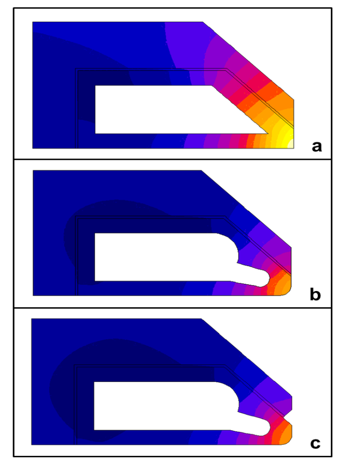
Figure 2: Thermal analysis of the influences concentrator and pocket a) Typical, but improper cooling path and concentrator design. (b) Preferred cooling path with unchanged concentrator. (c) Preferred cooling path and concentrator design.
In practice, the authors have seen many instances of the use of water pocket or braze seams on the outside diameter of the head (Figure 3). These “odd” seams or braze lines can cause greatly reduced cooling in the coil head. With proper placement of the pocket and cover, these issues can be eliminated completely. This leads to brazing of the covers to the loop. By using copper filler or copper brazing rod the loop temperatures during assembly can far exceed the temperatures needed for silver brazing. This can cause the copper to become annealed and soft, which when put into production only promotes a faster failure rate. It is suggested to use a silver (15%) solder to braze in the cover. This will keep the loop temperatures down during construction. When the coil brazing is complete, it is suggested after final assembly to anneal the inductor as a whole to relieve work stresses built up during sandblasting and calibration. These are basic steps or building blocks suggested when laying out the copper heads of a single shot stem coil.
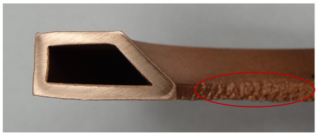
Figure 3: Example of overheated inductor loop due to poor cooling or improper concentrator design (encircled in red). The cross-section shown is similar to the modeled cross-section.
There are some basic steps that should be followed when designing the magnetic flux concentrator as well. In general we should avoid using sharp points or knife edge corners in any concentrator design. This can be avoided by proper use of a chamfer or radius. This can even work to your advantage as a place for epoxy/glue build up for proper adhesion to the copper. Splitting the concentrator into “pie wedge” shapes around the lower loop (Figure 4) can help extend the coil life for two reasons. First, the concentrator material will hold up longer without cracking from the flexing and vibration of the coil while running. Secondly, a space between concentrator pieces will alleviate the heavy loading on the heat face of the loop to help lower the overall temperature. There has been evidence of this already in use by customers of Fluxtrol.
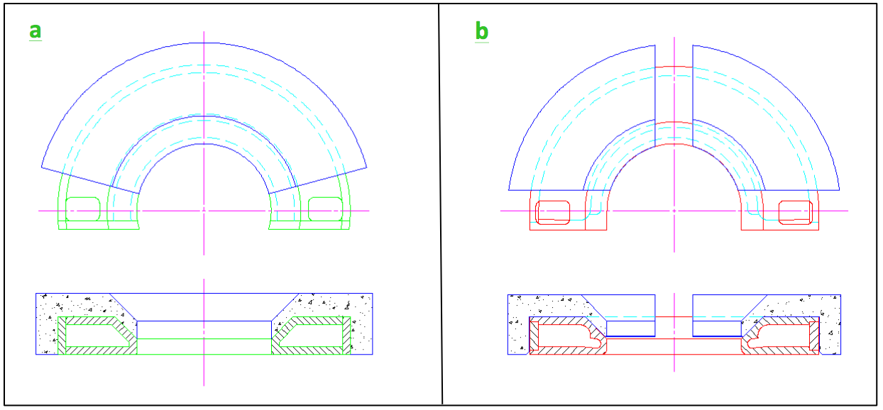
Figure 4: Examples of improper (a) and proper (b) magnetic flux controller design and application
The last major point to address on best coil design practices is the water/coolant flow thru the inductor. The use of booster pumps in problematic situations is encouraged. Yet another option is to add supply lines (two) to the lower loop, as shown in Figure 5. By adding two inlets (preferable) or outlets to the lower loop you can create two separate water/coolant circuits to the inductor, therefore making a shorter path for the water to flow and help remove the heat faster. Check to make sure that the water/coolant is being fed to the coil before going to other components of the system and sufficient water/coolant is reaching the inductor.
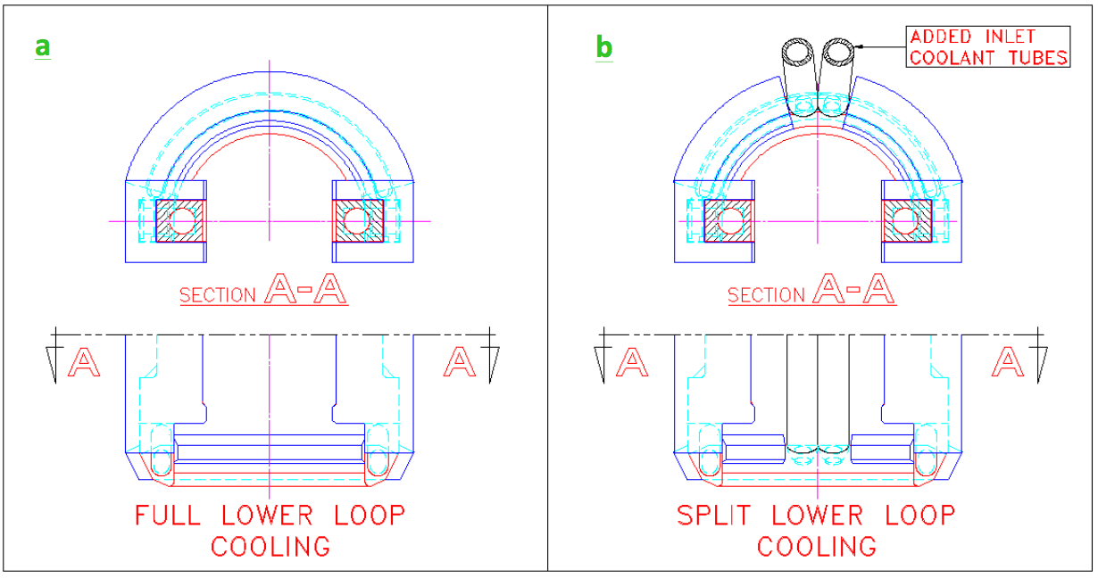
Figure 5: Examples of improper (a) and proper (b) water circuit design for increasing flow through a very heavily loaded inductor with a booster pump
Conclusions
With the use of good design and manufacturing practices, one can improve coil longevity and improve production quality. An automotive CVJ stem hardening coil was selected as an example of an inductor that in some instances can have a short lifetime. The causes of failure in this type of inductor are typically related to overheating of the nose on the bottom loop due to high power density. Design guidelines for bottom loop geometry, water pocket design, materials, magnetic flux controller geometry and assembly techniques were given. The best practices were explained and illustrations given. The authors have used these techniques in practice to increase coil lifetimes from thousands of pieces to hundreds of thousands of pieces in this type of application.
References
[1] R.C. Goldstein, W.I. Stuehr, and M. Black, Design and Fabrication of Inductors for Induction Heat Treating, ASM Handbook Volume 4C, pages 588-606, ASM International, 2014.
[2] W.I. Stuehr and D. Lynch, How to Improve Inductor Life, 23rd ASM Heat Treating Society Conference, September 25-28, 2005, Pittsburg, PA, USA.
[3] V.I. Rudnev, Systematic Analysis of Induction Coil Failure, Part 1-11, Heat Treating Progress Magazine, August 2005 – September/October 2007.
[4] R.C. Goldstein and V.S. Nemkov, Influence of Cooling Conditions on Induction Coil Temperatures, International Symposium on Heating By Internal Sources, 2007, Padua, Italy.
[5] H. Svendsen, and S.T. Hagen, Thermo-mechanical Fatigue Life Estimation of Induction Coils, International Scientific Colloquium on Modeling of Electromagnetic Processing, October 27-29, 2008, Hannover, Germany.
[6] K. Kreter,et. Al. Enhancing Induction Coil Reliability, Journal of Materials Engineering and Performance, December 2014, Volume 23, Issue 12, Pages 4164 –4169.
If you have more questions, require service or just need general information, we are here to help.
Our knowledgeable Customer Service team is available during business hours to answer your questions in regard to Fluxtrol product, pricing, ordering and other information. If you have technical questions about induction heating, material properties, our engineering and educational services, please contact our experts by phone, e-mail or mail.
Fluxtrol Inc.
1388 Atlantic Boulevard,
Auburn Hills, MI 48326
Telephone: +1-800-224-5522
Outside USA: 1-248-393-2000
FAX: +1-248-393-0277