Information
Authors: R.C. Goldstein, V.S. Nemkov and R.T. Ruffini
Magazine: Industrial Heating, November 2003
Coupled electromagnetic and thermal computer simulation provides a sufficient basis for process optimization and quality improvement in an aluminum-brazing application.
Automobile heat exchangers, such as heater cores, evaporators, condensers and radiators, are used for powertrain cooling, air conditioning, oil cooling, etc. The majority of passenger car heat exchangers today are made of aluminum or aluminum alloys. Even if the same engine is used for several automobile models, connections can vary due to different layouts under the hood. For this reason, it is standard practice for parts manufacturers to make several basic heat exchanger bodies and attach different connectors in a secondary operation.
Heat exchanger bodies usually consist of aluminum fins, tubes and headers brazed together in a furnace. After brazing, heat exchangers are customized for the given car model by attaching either nylon tanks or most commonly different aluminum pipes with connection blocks. The pipes are attached either by gas metal arc welding, or GMAW, (formerly known as MIG welding), flame or induction brazing. In the case of brazing, very precise temperature control is required due to the small difference in the melting and brazing temperatures for aluminum (20-50 C, or 35-90 F, depending on alloy, filler metal and atmosphere), high thermal conductivity of aluminum and close proximity to other previously brazed joints.
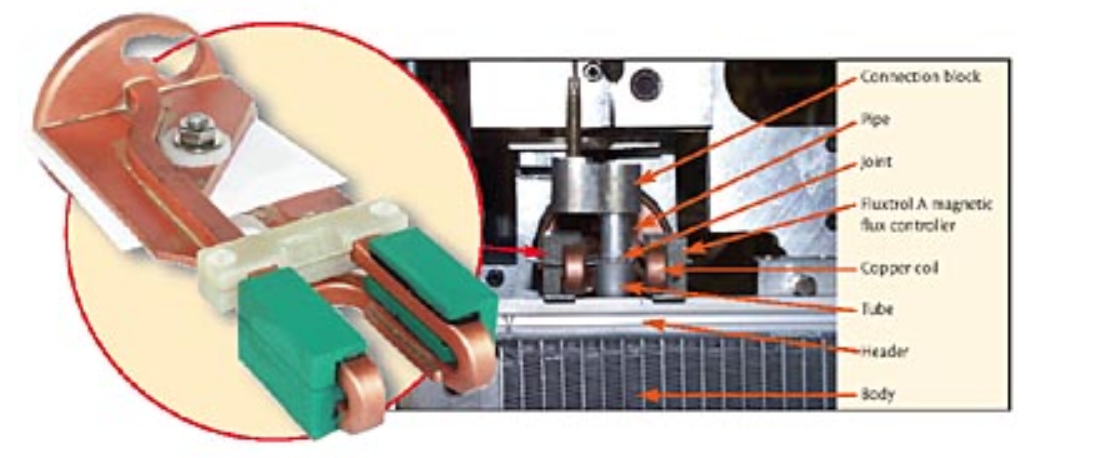
Induction is a common method for brazing various pipes to heat exchanger headers. Figure 1 shows an induction brazing set-up for brazing a pipe to a tube on a heat exchanger header. Due to the requirements for precise heating, the face of the induction coil must be in close proximity to the joint to be brazed. Therefore, a simple cylindrical coil cannot be used because the part could not be removed after the joint is brazed.
There are two main induction-coil styles used to braze these joints: clamshell and "horseshoe-hairpin" style inductors. Clamshell inductors are similar to cylindrical inductors, but they open to allow part removal. Horseshoe-hairpin inductors are shaped like a horseshoe for loading the part, and are essentially two hairpin coils on opposite sides of the joint.
The advantage of using a clamshell inductor is that heating is more uniform in circumference and relatively easy to predict. Disadvantages are that the mechanical system required is more complicated and the high current contacts are relatively unreliable.
Horseshoe-hairpin inductors produce more complicated 3-D heat patterns than clamshells. An advantage is simplified part handling.
Computer simulation optimizes brazing
A large heat-exchanger manufacturer was having quality problems with brazing the joint shown in Fig. 1 using a horseshoe-hairpin style inductor. The braze joint was good for the majority of parts, but heating would be totally different for some parts, resulting in insufficient joint depth, cold joints and filler metal running up the pipe wall due to local overheating. Even with testing of each heat exchanger for leaks, some parts still leaked at this joint in service. Centre for Induction Technology Inc. was contracted to analyze and solve the problem.
The power supply used for the job has a variable frequency of 10 to 25 kHz and rated power of 60 kW. In the brazing process, an operator installs a filler metal ring on the pipe end and inserts the pipe inside the tube. A heat exchanger is placed onto a special rig and moved inside the horseshoe inductor.
The entire brazing area is prefluxed. The frequency used to heat up the part typically is 12 to 15 kHz, and heating time is around 20 seconds. The power level is programmed with linear reduction at the end of the heating cycle. An optical pyrometer turns off the power when the temperature on the back side of the joint reaches a preset value.
There are many factors that can cause the inconsistency the manufacturer was experiencing, such as variation in joint components (dimensions and position) and unstable and variable (in time) electrical and thermal contact between the tube, pipe, filler ring, etc. Some phenomena are inherently unstable, and small variations of these factors can cause different process dynamics. For example, the open filler metal ring can partially unwind under the electromagnetic forces, and the free end of the ring may be sucked back by capillary forces or remained unmelted. The noise factors are difficult to reduce or eliminate, and the solution to the problem required increasing the robustness of the total process. Computer simulation is an effective tool to analyze and optimize the process.
During the evaluation of the brazing process, strong electrodynamic forces were observed. At the moment the power is turned on, the horseshoe coil clearly experiences an expansion due to a sudden application of electrodynamic force. Thus, the inductor was made mechanically stronger, including incorporating an additional fiberglass (G10) plate connecting the roots of two hairpin coils. The other demonstration of electrodynamic forces present was the shifting of molten filler metal away from the areas close to copper turns where the magnetic field is stronger. In a normal process, filler metal distributes uniformly around the joint due to capillary forces and gravity in contrast to an abnormal process where filler metal may run out of the joint or move up along the pipe surface.
Because aluminum brazing is a very complicated process, it is not feasible to expect an accurate simulation of the whole chain of mutually coupled phenomena (electromagnetic, thermal, mechanical, hydrodynamic and metallurgical). The most important and controllable process is the generation of electromagnetic heat sources, which were analyzed using the Flux 3D program. Due to the complex nature of the induction brazing process, a combination of computer simulation and experiments was used for process design and optimization.
Analysis of existing process
A common rule of thumb in induction heating is that the heating pattern resembles the shape of the induction coil, and the highest temperature is closest to the induction coil face. This was not the case for this brazing process. While it was not possible to measure the actual temperature distribution of the parts at the plant, an indirect evaluation was made by observing the part surface. (The surface of the aluminum would be a different color after the process was completed because the aluminum surface reached a temperature close to the brazing temperature.) Microscopic evaluation of the braze joints showed that the coloration line was a good indicator of internal joint depth. According to the color and microscopy, the braze depth for good parts was deeper at the front and back of the joint than on the sides, which were closest to the induction coil-an odd condition for induction heating.
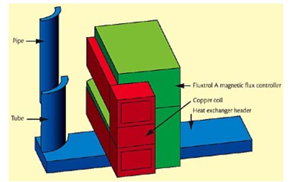
As noted above, it is not possible to model all of the phenomena involved in the brazing process, so the main variables used for comparison were eddy-current distribution, power density distribution and total induced power in the different pieces (pipe, tube and body). To keep the problem manageable for simulation, only 1/4 of the system was used (Fig. 2).
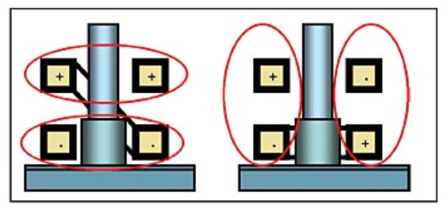
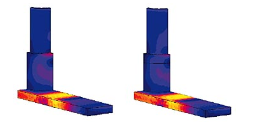
In the problem formulation, two main variables were discovered that had a significant influence on the distribution of power in the system: coil crossover and joint contact. The way the crossover that connected the two hairpin coils of the horseshoe-hairpin inductor was made has a very strong influence on the electromagnetic system description. The crossover used in production connected the two hairpin coils diagonally, which exposed the pipe and tube to a transverse magnetic field. By comparison, a crossover made horizontally would expose the tube to a longitudinal electromagnetic field (Fig. 3). The difference between the two systems was studied by changing the boundary conditions along the centerline.
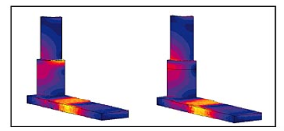
The second factor was the electrical contact in the joint area. As discussed above, before the filler metal is molten, the contact in the braze joint is uncertain. Using the induction coil with a diagonal crossover, the current paths and induced current density distribution are significantly different for good and bad contacts (Fig. 4). The current flows from the pipe to the tube when the electrical contact is good, but when there is no contact, the current must wrap around the inside of the tube to be continuous. During the heating process, the aluminum expands, improving the electrical contact, and when the filler metal flows, there is good contact. Thus, if there is some partial electrical contact or if contact is established at different times, heating dynamics can be significantly different.
The simulation also clearly shows that the highest temperature should be on the front and back of the tube and not on the sides as is shown in practice due to higher current density, though local overheating of the tube edge near the face of the induction coil may be observed at the beginning of heating.
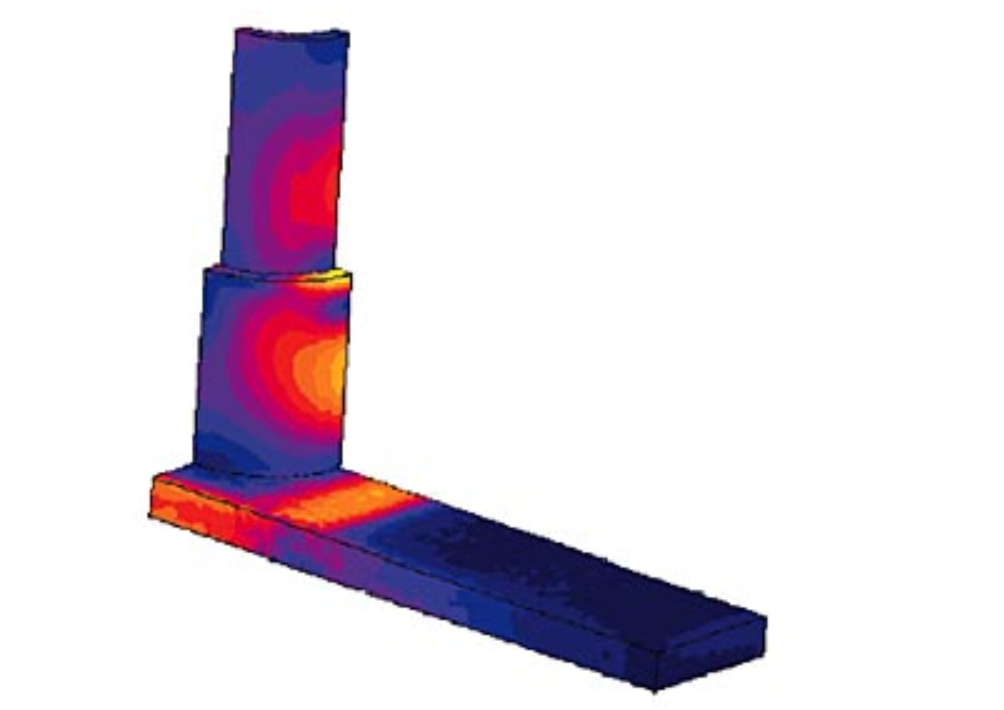
The current density distribution for the same induction coil geometry, but with the horizontal crossover is shown in Fig. 5. The difference between the current density distributions with no contact (left) and good contact (right) is much smaller than for the diagonal crossover, which is desirable. Therefore, the process is less sensitive to contact in the joint area. However, much more power is induced in the header and much less in the joint area, which leads to a much slower brazing process.
Optimized process design
CIT determined that several steps were necessary to improve the robustness of the induction brazing process. The first was to use the horizontal crossover to reduce the sensitivity to joint contact and part position inside the inductor. Due to production demands, a longer cycle time was not an option, so the distribution of power in the joint area had to be changed significantly. Therefore, it was necessary to shift more power from the tank to the joint area. Compared with the distributions shown in Fig. 4 for the existing coil, more power needed to be moved to the tube to prevent filler metal run up and to promote the filler metal to flow deeper into the joint, reducing the probability of a defect.
The copper coil and magnetic flux concentrator dimensions were modified to shift more power from the tank to the joint area. The main change was the addition of a 1.5 mm (0.06 in.) thick piece of Fluxtrol A to the bottom of the lower turn to shield the header from the magnetic field and focus the current density in the joint area. Figure 6 shows the induced current density distribution for the optimized induction coil. Much less power is induced in the header relative to the tube and pipe. At the same time, the area of high current density is lower in the tube, which leads to a greater joint depth.
A prototype induction coil was made based on computer simulation. With only minor modification of the magnetic flux controller dimensions, high quality joints with greater depth were made in both laboratory and production conditions. It also was found that by slightly modifying only the magnetic flux controller dimensions, the induction coil could be used for brazing the whole family of pipes that were attached to the header. In addition to improved joint quality and consistency, the optimized inductors lowered cycle times by 15 to 30%.
Conclusions
Computer simulation cannot accurately predict the entire process dynamics and results in brazing applications (especially aluminum brazing) due to a set of mutually coupled phenomena, some of which are very difficult to describe mathematically. Coupled electromagnetic and thermal simulation provides a sufficient basis for process optimization and quality improvement. However, there was no opportunity to use coupled electromagnetic and thermal simulation of 3-D geometries at the time of the development of this induction brazing process, so only the 3-D electromagnetic program was used to calculate and optimize the induced power distribution in braze-joint components. A new induction coil geometry was proposed, which could be used for brazing an entire family of joints, adapting it to a particular application by varying the magnetic flux controller geometry. Experience shows that electrodynamic forces in a brazing system are high, and must be taken into account in induction coil design. Use of the new inductor designs at several production sites showed very good brazed joint quality and consistency.
If you have more questions, require service or just need general information, we are here to help.
Our knowledgeable Customer Service team is available during business hours to answer your questions in regard to Fluxtrol product, pricing, ordering and other information. If you have technical questions about induction heating, material properties, our engineering and educational services, please contact our experts by phone, e-mail or mail.
Fluxtrol Inc.
1388 Atlantic Boulevard,
Auburn Hills, MI 48326
Telephone: +1-800-224-5522
Outside USA: 1-248-393-2000
FAX: +1-248-393-0277