Information
Authors: Zhichao (Charlie), B. Lynn Ferguson, V. Nemkov, Robert Goldstein, John Jackowski, and Greg Fett
Location/Venue: ASM HTS 15 Detroit, MI
Topic: Stress Evolution
Abstract
Previous work was reported on the induction hardening process for a 1541 steel axle shaft. This presentation compares the previous results with the stress formation dynamics in the same shaft made from steels with lower hardenability. Hardened using a scan heating method and a trailing PAG spray quench, several steels having lower hardenability were modeled using the same heating schedule so that the depth of austenite formation is similar in all cases. During spray quenching, the hardened case is shallower as steel hardenability is reduced. This leads to differences in the magnitude of compressive and tensile stresses and their distributions. In turn, the potential for internal cracking is reduced as the stress transition zone is altered by the thickness of the diffusive phase layer between the martensitic case and the ferrite-pearlite core of the shaft. The next step is to investigate these effects on the torque carrying ability of the shaft.
Introduction
Axle shafts are typically case hardened using induction. In this process, the surface layer of a steel component is heated to form austenite, and then spray quenched to form martensite. The result is a hardened layer that is under residual compression and a core that is under residual tension. There is a transition from compression to tension at the case – core interface, and the maximum residual tensile stress usually exists adjacent to this transition. The magnitudes of the peak stresses and the sharpness of the transition are dependent on the process variables such as the frequency, power, heating time and dwell time after heating and before the quench. The steel hard enability also affects the stress levels and the transition characteristics.
During service the applied stress is basically additive to the residual stress state achieved by case hardening. Because the peak residual tension occurs in the core just under the hardened case, a high applied stress may initiate fatigue cracks at the case – core interface, and if present, these cracks will lead to premature failure. The location and magnitude of the peak residual tensile stress and the sharpness of the transition from compression to tension have direct impact on part performance.
The objective of this model based study was to examine the effect of steel hardenability on both the magnitude of residual stresses and the sharpness of the transition zone. To do this, several steel alloys were selected that have different hardenability but that produce martensite of similar strength and hardness. For the simulations, one set of time-temperature histories was used so that all of the representative shafts were heated to the same temperature state before spray quenching.
Alloys Studied
Three steels were modeled in this study, and their chemistries are listed in Table I. These steels represent typical material selection options in terms of hardenability, alloy content and cost. The hardenability of these alloys were calculated using a published hardenability calculation method based on chemistry[1], and the values are reported in Table II. Table II also reports calculated martensite start temperatures for these steels. From these data, the differences in hardenability are significant but the Ms temperatures are similar.
| Alloy | C, w/o | Mn, w/o | Si, w/o | Cr, w/o | Ni, w/o | Mo, w/o | Fe |
|---|---|---|---|---|---|---|---|
| 1040 | 0.40 | 0.75 | 0.2 | 0.05 | 0.05 | - | Balance |
| 1541 | 0.41 | 1.50 | 0.25 | 0.05 | 0.15 | - | Balance |
| 4140 | 0.40 | 0.87 | 0.25 | 0.95 | 0.15 | 0.20 | Balance |
| Alloy | Calculated DI, mm[1] | Martensite Start Temperature, C |
|---|---|---|
| 1040 | 29.9 | 306 |
| 1541 | 58.8 | 311 |
| 4140 | 129.2 | 327 |
Model Development & Procedures
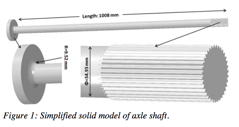
The axle shaft modeled, shown in Figure 1, has an overall length of just over 1 m, and the shaft diameter is 34.9 mm. The model development and the procedures followed to model the induction hardening process for this shaft have been discussed in detail in these references.[2,3] The following is a brief synopsis.
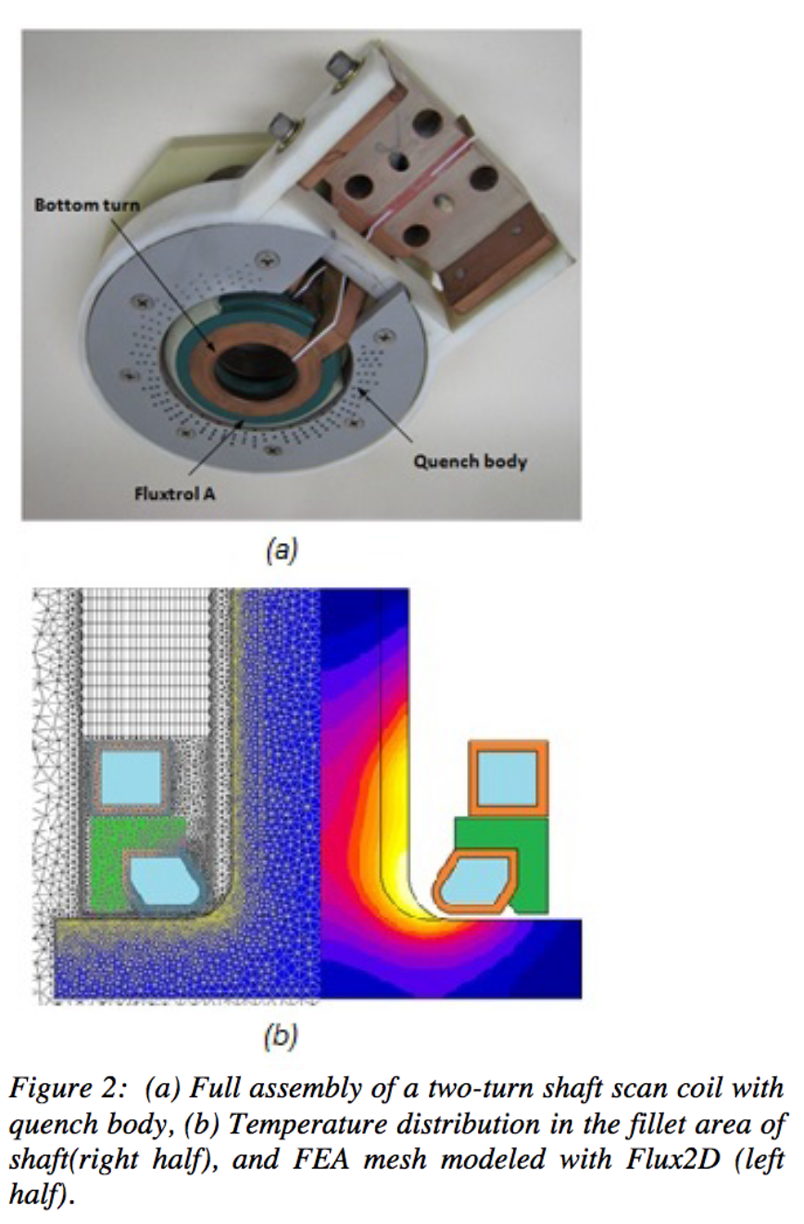
The axle shaft is positioned vertically with the flange on the bottom of the fixture during the scanning induction hardening process. The distance between the inductor and where the spray hits the shaft is 25.4 mm. The process begins with a nine second dwell to heat the flange/fillet region while the spray is off. Scanning and spraying then begins, with the initial inductor travel speed of 15 mm/s. After scanning for 1.5 seconds, the scan speed is decreased to 8 mm/s and it remains at this speed. The power to the coil is turned off after an additional 119.65 seconds. Spraying continues as the inductor assembly traverses along the spline section of the shaft to complete the martensitic transformation of the final austenitized section of the shaft.
Power density vs. time histories predicted by Flux2D were mapped to the DANTE model. The temperature distributions predicted by Flux2D and DANTE throughout the process were compared quantitatively to verify the accuracy of data mapping between the two analysis codes. Error minimization during mapping is required, and if necessary, meshes are redone to improve accuracy of this important mapping step.
Results and Discussion
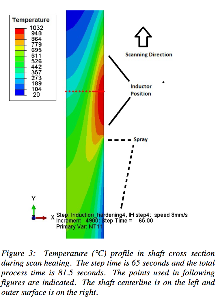
For this study, one location at about mid-length of the shaft was selected to compare stress, displacement and phase distribution. Figure 3 shows the temperature in the cross section of the shaft at 81.5 seconds of total process time when the inductor has reached this mid-length location. The points on the cross-section that will be addressed are shown, and the heated surface layer is evident. The approximate position of the inductor is indicated, as is the approximate application of the spray quench. The direction of scanning is also indicated in Figure 3.
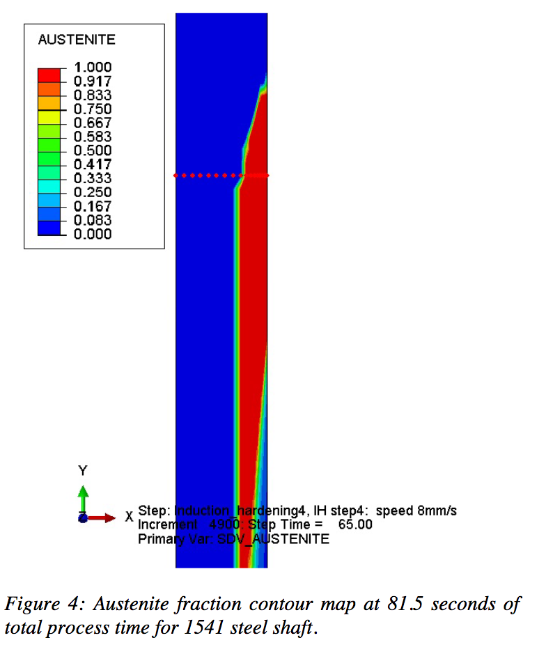
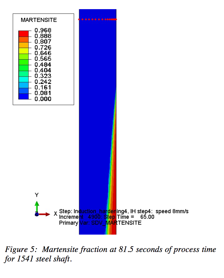
Figures 4 and 5 show the austenite and martensite phase fraction distributions for 1541 steel at the same process time of 81.5 seconds. The position of the shaft has been altered for viewing, but the indicated points provide a reference. Comparing the temperature contours in Figure 3, the austenite contours in Figure 4, and the martensite contours in Figure 5, the location of the spray zone is evident. Austenite is present in the heated zone and at sub-surface locations where the spray is present, and martensite has formed on the quenched surface.
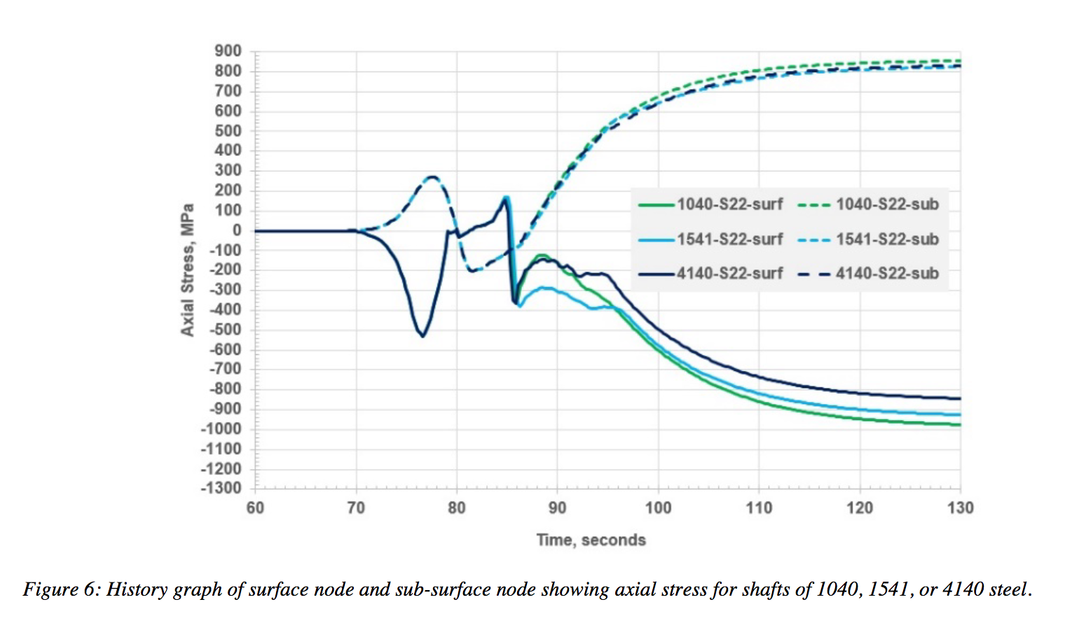
Figure 6 shows axial stress vs. time at the shaft surface and at a sub-surface location (beneath the hardened case) for shafts made of 1040, 1541 or 4140 steel. All three steels experience similar stress cycles during the heating and spray quenching steps, with the final stress state being compression on the surface and tension inside the case-core interface.
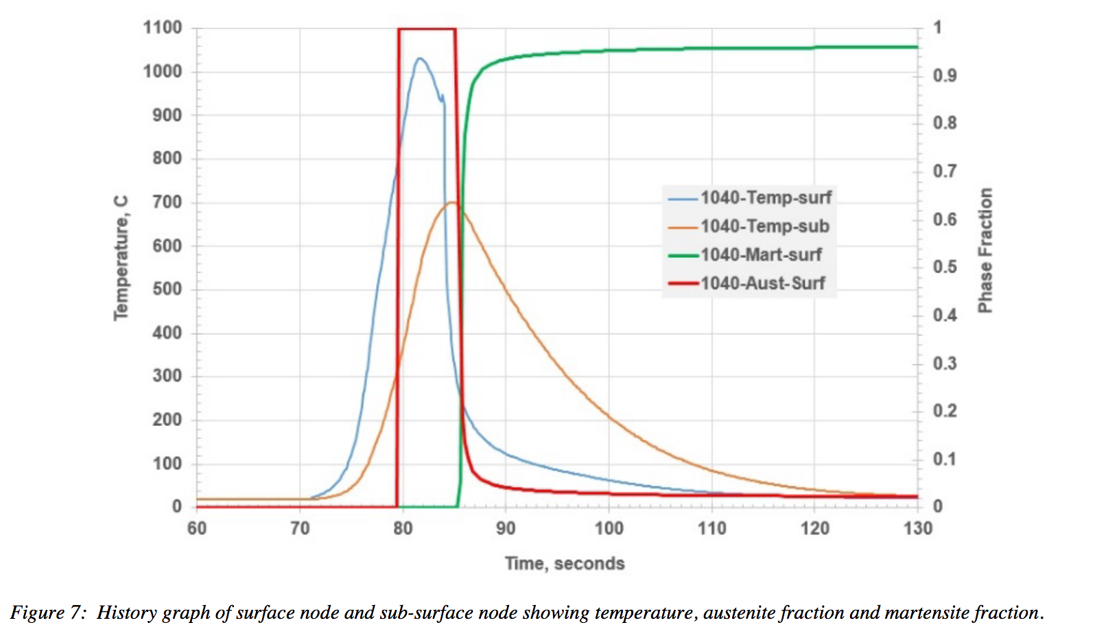
To understand the stress cycles shown in Figure 6, the history plots in Figure 7 for temperature, austenite fraction and martensite fraction for the 1040 steel shaft are helpful. The surface temperature is higher than the sub-surface temperature, so the thermal expansion of the surface is restricted by the core of the shaft, resulting in surface compressive stress and tensile stress in the core. As the surface transforms to face centered cubic austenite at about 79 seconds, there is a volumetric contraction due to the density increase and the surface compression is decreased. At the same time, the sub-surface tension is lessened. As the austenitic surface is initially spray quenched, it thermally contracts and surface tension is experienced. However, at about 86 seconds the surface transforms to martensite, and the volumetric expansion associated with the phase change imposes surface compression. The region inside of the hard case was heated but to a temperature too low for austenite to form. As the sub-surface cools, it thermally contracts and pulls the surface martensite into deeper compression. The strong martensite case restricts the core shrinkage and imposes tension in the core. The result is high surface compression and relatively high tension just beneath the case-core interface.
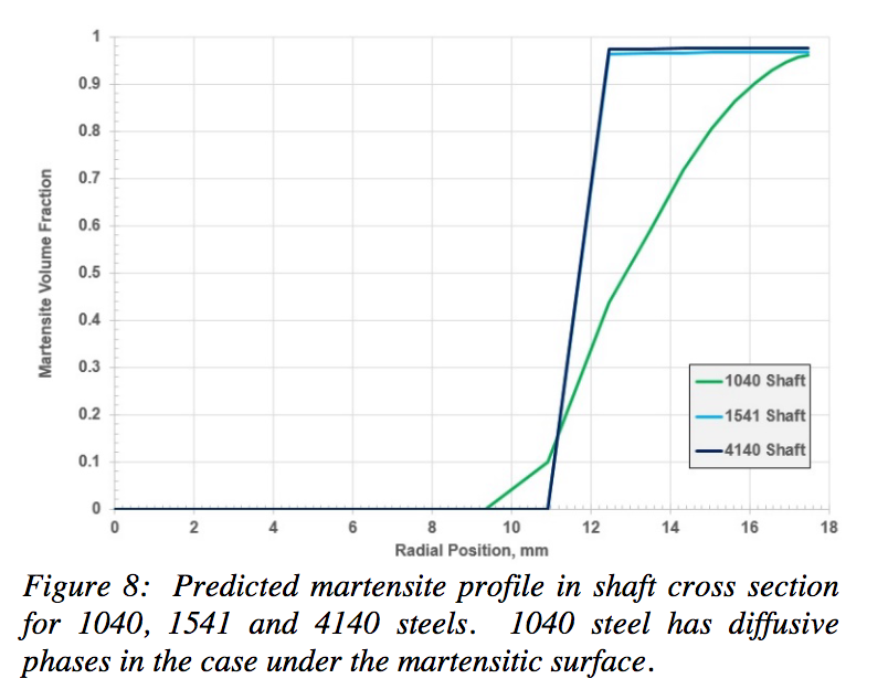
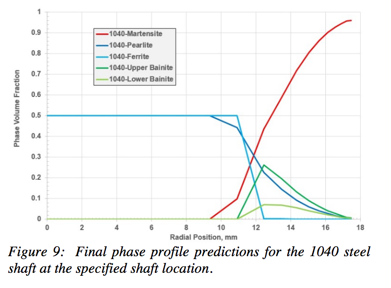
The hardenability of the alloy is shown to have a small effect on the level of surface compression. Interestingly, the 1040 steel shaft, which has the lowest hardenability, is predicted to have the highest surface compression. This is because the 1040 steel did not completely transform to martensite in the entire case, as shown in Figure 8. For induction hardening where the steel chemistry is constant, i.e. no carburization, the spray quenching causes the austenite decomposition to proceed from the surface to the interior. Martensite will start forming first on the quenched surface. Figure 8 shows that both 1541 and 4140 have fully martensitic hardened cases with no diffusive products. As subsurface martensite forms, there is a reduction in the residual compressive stress in the already formed martensite even while the newly formed martensite contributes to the bulk surface compressive stress. For 1040 steel, the inner portion of the austenitized layer transformed partially to bainite, as shown in Figure 9. The lower volumetric expansion during formation of subsurface bainite as opposed to subsurface martensite in the 1040 case causes less of a reduction in compressive stress in the already formed martensite. This is responsible for the higher compressive surface stress predicted for the 1040 steel shaft.
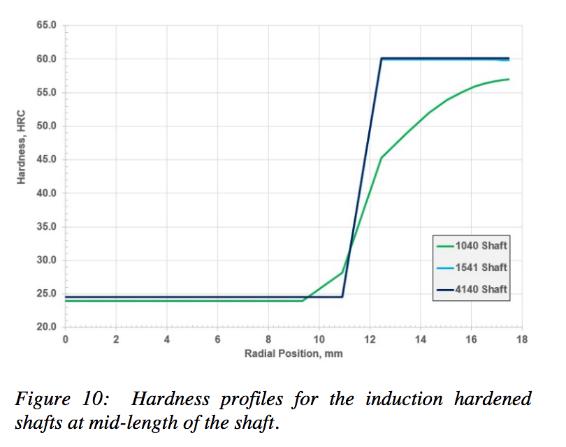
An important difference between the steels is the case hardness profile. Because of lower hardenability, the hardness profile for the 1040 steel tapers off from the surface to the interior due to the presence of the softer diffusive phases in the inner edges of the prior austenitized zone, as shown in Figure 10. The profiles for 1541 and 4140 steel in Figure 10 remain flat and high through the hardened case. Consequently, the strength of the 1040 case decreases from the surface inward through the case. During service, shafts such as this one transmit torque, and the torsional stress is maximum at the shaft surface and it decreases linearly to the shaft center. The residual stress is additive, so the surface compression lowers the effective surface stress. Since the 1040 steel strength decreases at the inner region of the cases, and for all three steels the core has the strength level of the starting stock microstructure, it is likely that failure will be initiated at a sub-surface location. This is especially true for a low hardenability steel such as 1040, and much less a possibility with the higher hardenability steels 1541 and 4140.
Summary
A modeling study to examine effects of steel hardenability on the phase make-up and stress state in an induction hardened shaft was conducted. The three steel grades were 1040, 1541 and 4140, listed here from lowest to highest hardenability. Using the same hardening schedule for the three steels, a similar residual stress profile was predicted for these shafts. However, because of hardenability differences, the 1040 shaft was predicted to have diffusive phases formed at the inside region of the hardened case while both 1541 and 4140 steel shafts transformed completely to martensite during spray quenching of the austenitized case. The result was a predicted difference in hardness profile for the shafts, with the 1040 steel shaft having lower hardness through the case. The thinner martensitic case for the 1040 steel shaft is expected to result in reduced performance. The consequence of the thinner martensite case for the 1040 steel shaft is a strength gradient in the case section which the higher hardenability steels, 1541 and 4140 steel, do not have.
Future studies will involve extending this study to measure torsion performances.
Acknowledgement
The authors gratefully thank Greg Fett of DANA for discussions on axle shaft production and service.
References
[1] Republic Alloy Steels, Republic Steel Corp., pp 75-97, 1968.
[2] Zhichao Li, B. Lynn Ferguson, Valentin Nemkov, Robert Goldstein, John Jackowski, Greg Fett, “Effect of Spray Quenching Rate on Distortion and Residual Stresses during Induction Hardening of a Full-Float Truck Axle,” Proceedings of HTS 2013 Conference, ASM International, Metals Park, OH, 2013.
[3] Zhichao (Charlie) Li, B. Lynn Ferguson, Robert Goldstein, John Jackowski, Valentin Nemkov, Greg Fett, “Stress Generation in an Axle Shaft during Induction Hardening,” ASM-HTS and IFHTSE Conference, Orlando FL, June 2014.
If you have more questions, require service or just need general information, we are here to help.
Our knowledgeable Customer Service team is available during business hours to answer your questions in regard to Fluxtrol product, pricing, ordering and other information. If you have technical questions about induction heating, material properties, our engineering and educational services, please contact our experts by phone, e-mail or mail.
Fluxtrol Inc.
1388 Atlantic Boulevard,
Auburn Hills, MI 48326
Telephone: +1-800-224-5522
Outside USA: 1-248-393-2000
FAX: +1-248-393-0277
Related Topics
- Effect of Steel Hardenability on Stress Formation in an Induction Hardened Axle Shaft
- Effect of Spray Quenching Rate on Distortion and Residual Stresses during Induction Hardening of a Full-Float Truck Axle
- Modeling Stress and Distortion of Full-Float Truck Axle During Induction Hardening Process
- Stress and Distortion Evolution During Induction Case Hardening of Tube