Information
Authors: V. NemkovLocation/Venue: HES 13 Padua, Italy
Topic: Magnetic Flux Control
Download Full Paper
Download Presentation
Abstract
It is well known that performance of some induction systems may be significantly improved by application of magnetic flux controllers [1,2]. They are used to concentrate, shield and/or redistribute the magnetic field which generates power in the part. Theoretical and practical evidences are presented in the paper, which show that there is still significant potential for improvement in innovative and traditional induction technologies due to magnetic flux control. Utilizing magnetic flux controllers in heat treating processes results in excellent heat pattern control and improvement of parameters of inductors and entire power delivery systems. In melting systems, especially in the case of vacuum furnaces, cold crucible and other specialty furnaces, the magnetic control can provide energy savings, magnetic field shielding, shorter melting cycles and optimized field distribution for metallurgical processes. Comparison of different groups of materials for magnetic flux control (laminations, ferrites and Soft Magnetic Composites, aka Magnetodielectrics) is also presented in the paper. Several examples of magnetic flux control illustrate the presented material based on more than 20 years of R&D and practical experience of scientists and practitioners at Fluxtrol Inc.
Introduction
Magnetic flux control, i.e. modification of magnetic field distribution and control of its intensity and pattern may be accomplished by variation of the coil turn shape and positioning, and by insertion of the non-magnetic shields or magnetic templates that may be called magnetic controllers. Each method of magnetic control has its own advantages, drawbacks and limitations.
In majority of papers on induction coil design the main attention is paid to optimization of active conductors, their position, number and size. Designers tend to avoid use of additional coil components for magnetic flux control in order to simplify design, reduce cost and avoid potential life time reduction. This approach, based on long term experience and traditions, is understandable but it is correct only partially. In today’s competitive market with new materials and technologies, more strict demands to product quality and ergonomic requirements force us to review the existing guidelines and make corrections to design strategy. The main tool for that is computer simulation which can predict not only the process parameters but also service properties of final products [4]. Different methods of magnetic flux control must be considered in the process of new system development and modification of existing equipment.
Non-magnetic controllers (shields), typically made in the form of copper rings (Faraday Rings - FR), sheets or massive copper blocks, are often called “Robber Rings”. Their use results in increase of the coil current, reduction in the induction coil power factor and efficiency. However they may be less expensive and give good shielding results.
Use of magnetic flux controllers, made of soft magnetic materials (steel laminations, ferrites and magnetic composites), are mainly addressed in this paper. It is shown that in the case of shielding the best results may be achieved by using a combination of Faraday rings and magnetic controllers. Application of magnetic controllers can increase field intensity in required areas (field concentration), change field distribution, shield certain areas from unintended heating and strongly reduce the magnetic field in external space.
Materials for Magnetic Flux Control
Faraday rings may be made from copper or from aluminum, which is lighter and several times cheaper for the same volume of copper. Higher resistivity of Al may be compensated by larger cross-section. At middle frequency when skin effect is typically high, the ”face” of the screen must be increased as root square from a ratio of resistivities of Al and Cu, i.e. only by 25 % in order to have the same losses.
For magnetic materials we can use laminations, ferrites and soft magnetic components (SMC), aka Magnetodielectric Materials (MDMs).
Use of ferrites for magnetic flux control in induction systems is limited to high frequency applications (typically above 100 kHz) such as impeders for HF tube welding, inductors for sealing and plastic welding, small brazing coils, etc. Other areas of successful application: HF transformers, sensors and small chokes in power supply control systems, etc. Advantages of ferrites are: wide frequency range (up to 13.56 MHz, relatively low magnetic losses, high permeability in weak fields and chemical resistance. However they have low saturation flux density (below 0.3-0.4 T), low Curie point (typically below 200-250 C with up to 350 C for some special types). Ferrites are sensitive to thermal shocks, brittle and very hard, which makes very challenging a task of complex geometries manufacturing by machining. These drawbacks limit their use at low and middle frequencies and in complex shape cases.
Laminations are the main material for low and lower range of middle frequencies (up to 30 kHz and even at 50 kHz in some special cases). They are used for matching transformers (up to 20 kHz), shunts and cores for induction melting furnaces, mass heating furnaces, large heat treating coils. Advantages of laminations: very large components of simple geometry may be made (such as furnace shunts), high saturation flux density (1.6-1.7 T), high permeability, low losses at low frequencies, high Curie point, good temperature resistance.
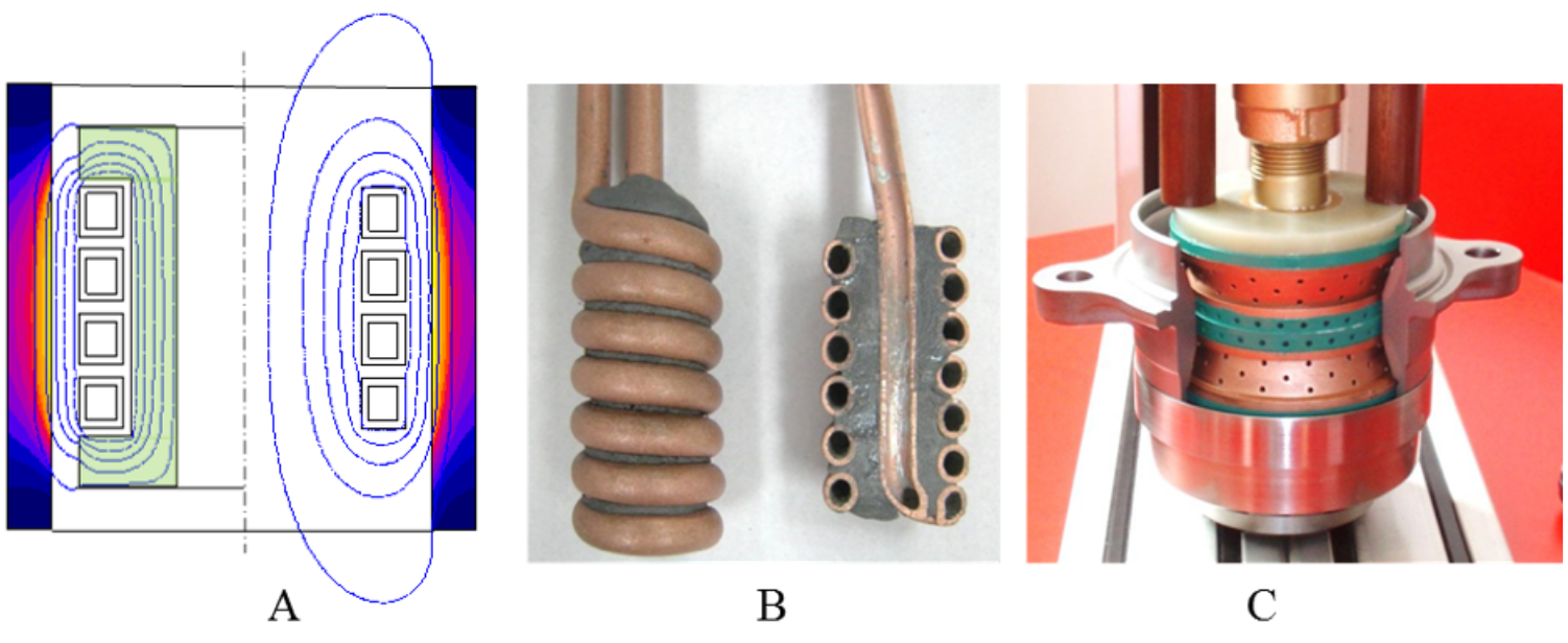
The drawbacks of laminations are: bad performance in 3D magnetic fields (overheating), limited machinability, manual assembling, frequency limits and complicated thermal management (cooling). Stamping and laser cutting still require some manual cleaning of burr and other defects. Fig. 1 shows induction coil for single-shot hardening of shaft with concentrator made from laminations. Poles of the concentrators are of different length for power distribution adjustment along the shaft.
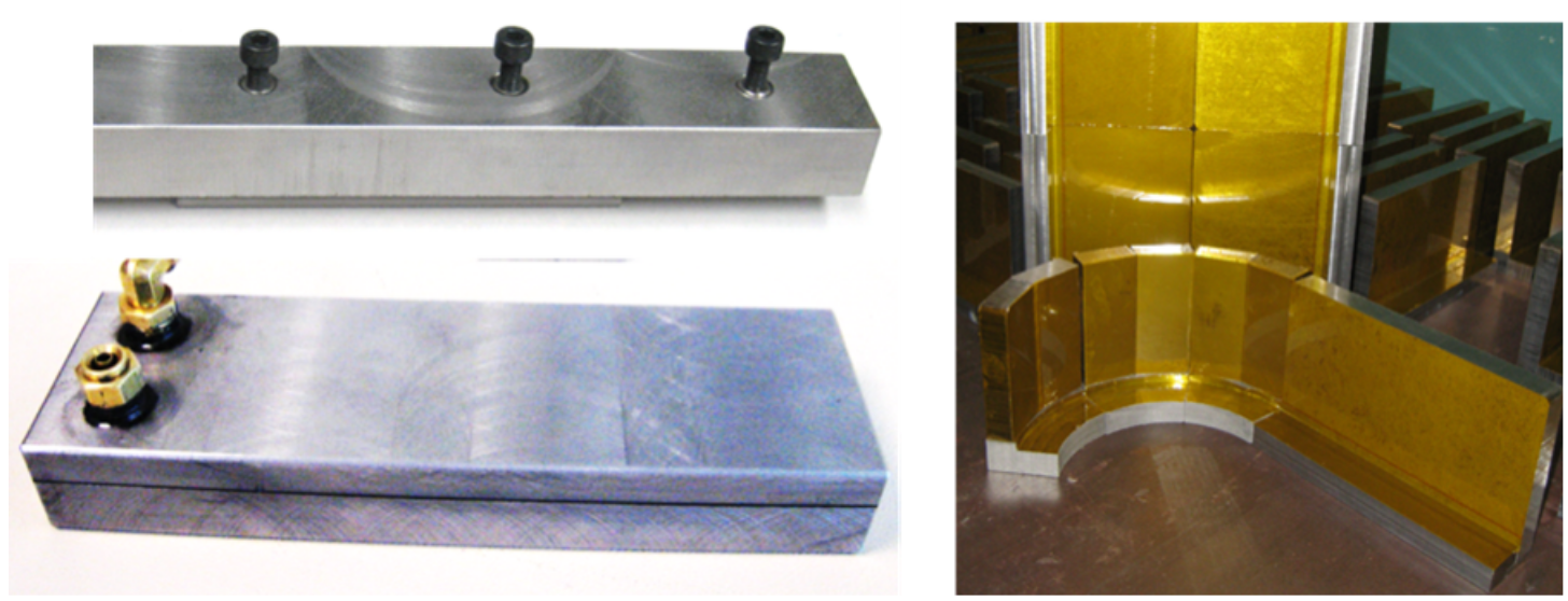
SMC is a class of materials that was significantly improved during the last decade. SMCs are made from ferrous particles (iron, its alloys, ferrites), covered with thin insulation layer, mixed with organic or inorganic binder, pressed at high pressure (up to 720 MPa and even higher) and cured or sintered. Majority of SMC used in induction industry has organic binder, which provides good machinability. All pressed materials have certain anisotropy (up to 1.5-2 times in permeability depending upon structure) but all of them work well in 3D fields. High frequency materials have low anisotropy. Possibility to work in 3D fields and good machinability are highly valued by the coil manufacturers. Different types of SMC cover the whole range of frequencies used in induction heating (50 Hz – 13.56 MHz). Losses at low frequency are comparable to laminations and at high frequencies – to ferrites. Temperature resistance is lower than for laminations but usually sufficient for induction applications. High thermal conductivity (up to 0.2 W/cmK) and possibility of effective thermal management using external or internal cooling can keep controllers safe in heavy loaded cases, fig. 2 [3]. The drawbacks of SMC are limited dimensions (up to 220 mm long plates at present time, figure 2, right) and higher price.
Several new materials have been introduced recently onto the market, e.g. Fluxtrol LF for low frequency applications and formable materials Alphaform, which can be applied to inductors of irregular shape manufactured with low tolerance.
Technical and economic analyses show that in some cases a combination of different materials give excellent results. For example, laminations may be used for the regular part of controllers and SMC for areas with complex shape and 3D field is the best solution.
Magnetic Control in Heat Treating
At the dawn of technology, the magnetic controllers were used on heat treating coils only occasionally [1]. In the process of technology development, due to more strict quality requirements, demand for higher production rates and lower cost, they are being used more and more. New materials and manufacturing technologies also contributed to this process. It is impossible to discuss here all types of heat treating operations: hardening, tempering etc. Let us consider only two typical applications – Crankshaft Hardening and Internal Heating.
Crankshaft Hardening
Crankshafts were the first induction hardened part in mass production [1] using clam-shell inductors (1934-35). U-shaped coils have been introduced in 1940-42 and both types of inductors are being used until now. In spite of almost 80 years of production history, there are new tasks (more complicated geometry and hardness pattern, reliability, lifetime, etc.) that require technology improvement. Main improvements are connected with innovative applications of magnetic controllers.
In clam-shell inductors, thin plates of magnetic controllers made of SMC provide precise control of heat pattern and simultaneously improve the system parameters. A simple example of the side controller application is presented in figure 2, generated by program Flux 2D.
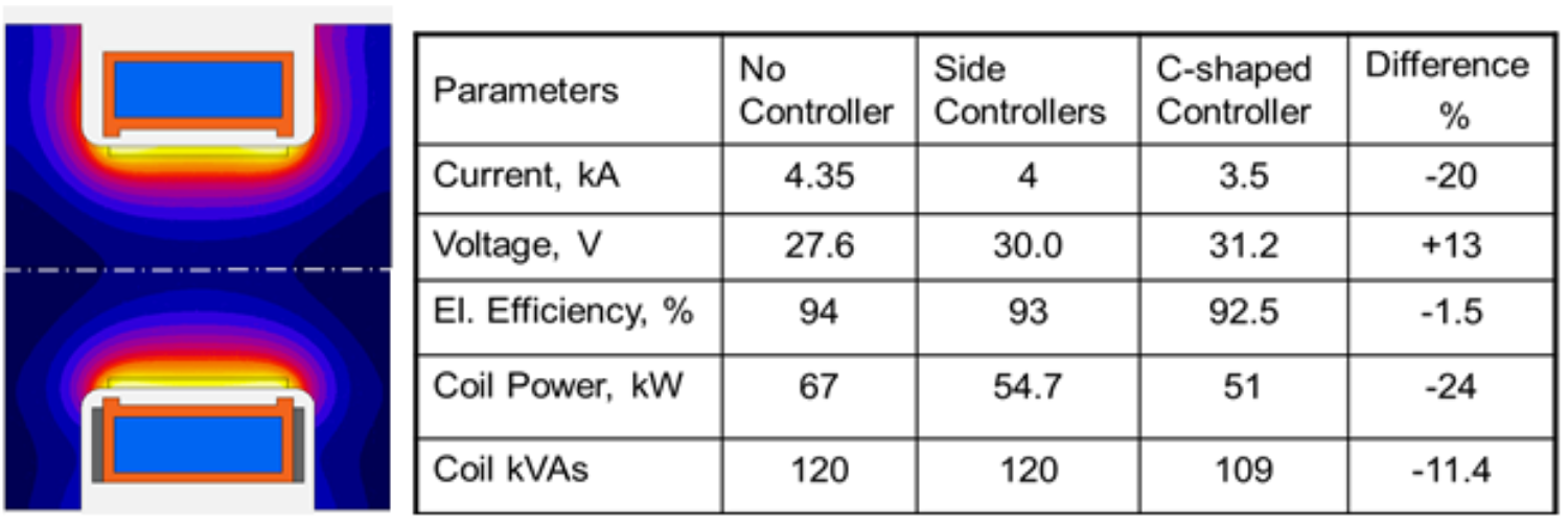
Comparison of pin heating by the cylindrical inductors with and without the side magnetic plates and also with C-shaped controller makes evident that controllers provide more accurate heat pattern control and reduce heating of the web [5]. These factors lead to treatment quality improvement, lower distortions and energy savings. It is important to mention that in this case, the C-shaped magnetic controller reduces required power by 24% and current demand by 20% while “traditionally defined” electrical efficiency is lower. It happens because of more efficient power distribution in the part, which overruns an increase of the coil resistance caused by current concentration on the coil conductor face.
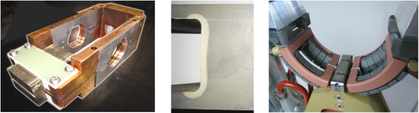
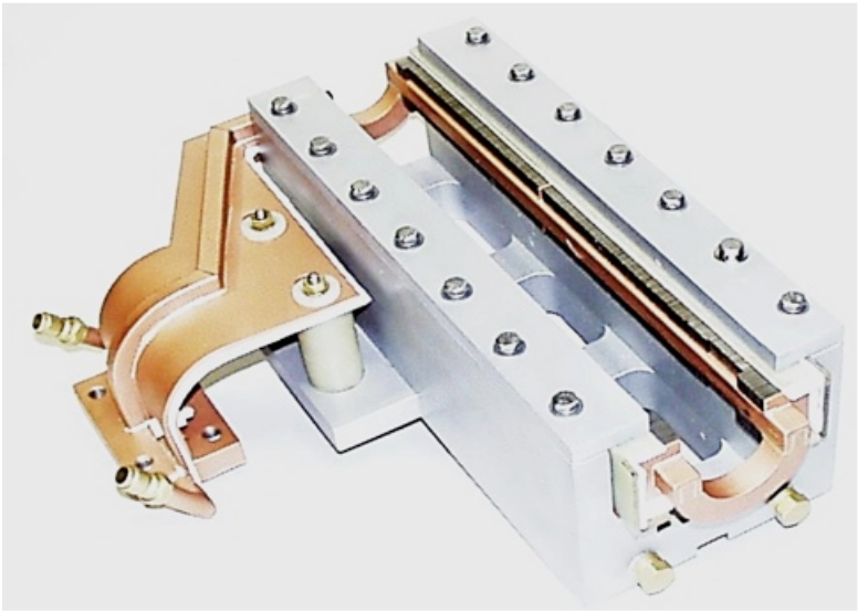
Another example of effective magnetic flux control is non-rotational hardening of crankshafts implemented in SHarP-C installations, Fig. 4. An inductor heats two pins or mains simultaneously. It consists of two parts, which aren’t connected electrically. The bottom part is connected to the power supplying circuit and may be called “active”. The top part of the inductor is short-circuited and may be called “passive”. Two parts of the inductor are “coupled” by means of magnetic coupler. Current in the active part induces a current in the opposite direction in the passive part. Thin plates of SMC material placed on the sides of both coil heads for precise heat pattern control along the pin circumference and for improvement of the coil efficiency.
Flux controllers made of laminations are traditionally used on U-shaped crankshaft hardening coils in order to distribute power in such a way that results in required heat pattern, including the patterns that extend onto the fillet, Fig.3, center. U-shaped coils are much more loaded because the coils cover only a small part of the pin surface, Fig.4. One of the drawbacks of such coils is insufficient coil lifetime due to copper cracking under the concentrators. It was found that replacement of laminations with SMC material (Fig.4, right) led to a significant increase in the coil life and to better heat pattern control.
Internal Inductors
Internal (ID) inductors are widely used for brazing, curing, heat treating and other operations. Application of magnetic controllers is especially important for ID coils because magnetic flux must flow in closed loop around the turns through the narrow space inside the coil. For this reason the current demand for ID coils without core is high and their parameters (efficiency, power factor) are lower than for external coils. Magnetic core magnetically expands the area inside the inductor thus strongly reducing additional coil current required to push the magnetic flux around the turns [6].
Simulation results for internal heating of a stainless steel tube by inductors with and without magnetic core are presented in Table 1 [6]. The part ID is 2.2”, wall thickness 0.25 mm; inductor has ID 1.4”, tubing 0.25 x 0.25”, length 1.2”. Magnetic core is made from SMC with permeability Mu = 40. Frequency is 15 kHz. Simulation was made under conditions of the same power of 10 kW being transferred into the part.
| Core | Ui, V | Ii, A | Pi, kW | Pw, kW | Eff-cy | Coil kVA |
|---|---|---|---|---|---|---|
| Yes | 46 | 875 | 12.0 | 10.0 | 84 | 40 |
| No | 44 | 1850 | 14.3 | 10.0 | 70 | 81 |
Furnace Shielding
Magnetic shielding may be necessary for three reasons:
- Reduction of losses in the furnace structure
- Reduction of the enclosure size for vacuum and atmosphere furnaces
- Reduction of the external magnetic field below the Maximum Permissible Exposure limits on work places.
There are two ways of shielding: magnetic shunts and Faraday rings, Fig.6, left. Computer simulation demonstrated influence of shielding type on the magnetic field pattern and furnace parameters (Table 2). Magnetic field reduction with distance from the coil is shown on Fig 6.
Fig.6. Magnetic shielding of furnace: left – magnetic lines for bare coil and coil with combined shield (shunt and Faraday rings); right – magnetic field strength variation with a distance from the coil OD
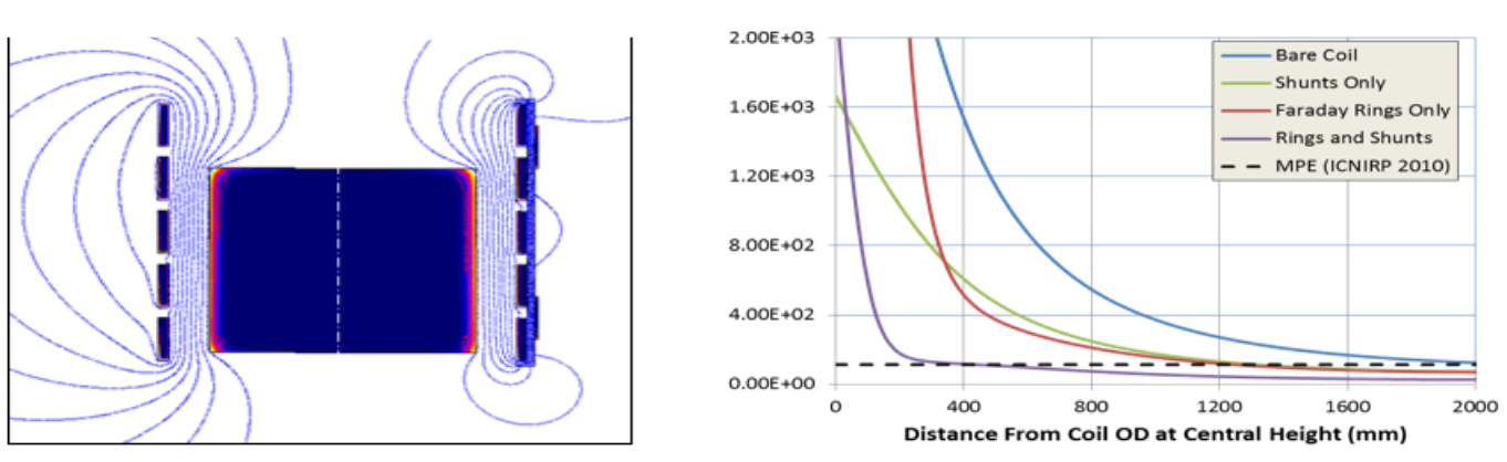
It is clear that combination of magnetic shunts and Faraday rings provide the most effective shielding with only small reduction in the furnace efficiency.
| Conditions | Pmelt kW | Prings kW | Pturn kW | Ptotal kW | U, V | I, A | kVAs | Eff. % | Field @ 500 mm from OD, A/m |
|---|---|---|---|---|---|---|---|---|---|
| Bare Coil | 200 | N/A | 33.9 | 234 | 825 | 5050 | 4170 | 85.5 | 1163 |
| Rings Only | 200 | 18.5 | 46.5 | 265 | 827 | 6810 | 5630 | 75.5 | 346 |
| Shunts Only | 200 | N/A | 36.8 | 237 | 848 | 4630 | 3926 | 84.4 | 437 |
| Shunts and Rings | 200 | 1 | 40 | 240 | 852 | 4760 | 4055 | 83.3 | 97 |
Melting Furnaces
Cold Crucible Furnaces
Cold crucible furnaces for melting metals have low electrical and thermal efficiencies. Electrical efficiency is especially low for short coils [7] and when there are Faraday rings.
![Fluxtrol - Magnetic Flux Control in Induction Installations - Figure 7 Cold crucible furnace with magnetic shunts and results of 2D simulation (left) [8]; meshed components and current distribution on the surface of fingers and Faraday ring (3D simulation), right: A – without magnetic inserts; B – with inserts](/images/magnetic-flux-control-in-induction-installations-figure-7.png)
Fluxtrol, Inc. made a profound study of the electrical parameters of cold crucible furnaces using computer simulation (2D and 3D models) and physical modeling. Figure 7, left, shows the furnace with magnetic shunts and magnetic field lines in the system (2D modeling). Some results of 3D simulation are given on Fig.7, right. One can see that magnetic shunts 1 with poles 2, additional magnetic inserts 3 in the slits and magnetic bottom ring strongly reduce the currents (pictures A,B) and losses in the crucible fingers and in Faraday ring 4 [9].
Furnaces with Ceramic Crucibles
High and middle capacity crucible furnaces for melting steel, aluminum and other materials typically have magnetic shunts in the form of lamination packages.
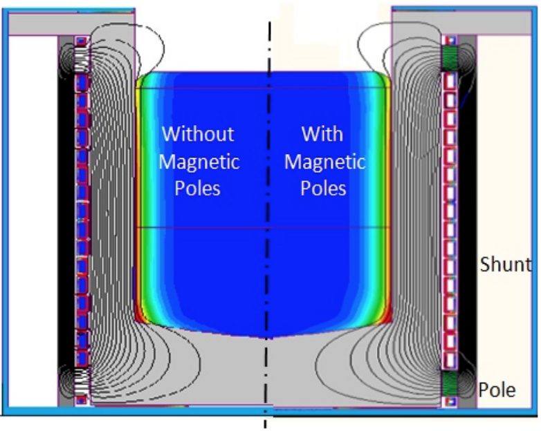
They are used for the coil shielding from the furnace structure and power factor improvement. Additional Faraday rings may be used near the top and bottom of winding for shielding of the top and bottom portions of the furnace structure. Possibility to improve the furnace performance using magnetic poles, Fig.8, was studied using 2D computer simulation. It was clear that these poles must reduce magnetic path reluctance and therefore the coil current demand. The question was how big improvements could be in technical and economical characteristics of the furnace and whole installation. Simulation was made for a typical mid-size furnace for melting steel: capacity is 10 tons, frequency 280-300 Hz, rated power 5000 kW and voltage 2 kV. Internal crucible dimensions are 1220 x 1020 mm; coil ID 1500 mm, height 1115 mm; winding has two sections with 8 turns each. Furnace has two Faraday rings and 16 shunts made of steel Fig.8. Magnetic lines of induction furnace for shunts with right) and without poles (left) (study made by Elmag Corp. for Fluxtrol, Inc.) M250-35A, thickness 0.35 mm. Poles were made from Fluxtrol LF. Losses in magnetic components have been taken into account using real loss curves for corresponding materials.
| Case | Load power kW | Frequency Hz | Furnace A | Coil Losses kW | Faraday Rings kW | Furnace Power kW | Efficiency % | Furnace kVAR's |
|---|---|---|---|---|---|---|---|---|
| With MP | 4110 | 286 | 24040 | 850 | 6 | 5000 | 82.2 | 47800 |
| W/O MP | 4110 | 291 | 25320 | 1155 | 36 | 5366 | 76.6 | 50,350 |
| Difference | 0 | - | -1280
-5% | -305
-26% | -30
-83% | -366
-6.8% | +5.6 | -2550
-5% |
Main results are presented in Table3. One can see that magnetic poles increase the overall furnace efficiency by 5% and reduce current and reactive power by 5%. Main gains in efficiency are due to reduced losses in the Faraday rings (6 times) and in winding (by 26%).
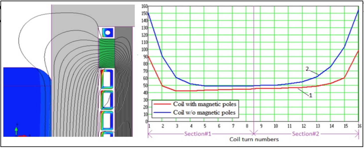
Big loss reduction in the coil winding can’t be explained only by lower current. It is also due to loss reduction in the end turns because poles make the magnetic field more uniform along the winding height (Fig. 9).
Economical evaluation of results shows that for the same installed equipment, the furnace production rate may be increased by 5.6%. In the case of the whole system modification and the same production rate, capital savings on equipment (inverter, capacitor battery, etc.) may be about $42,000 and annual savings of energy around $110,000 (for price 0.1 $/kW). Additional costs of material for poles will be around $25,000.
Conclusions
Theoretical studies and practical experience demonstrate that magnetic flux control is a very important component of optimal design of induction systems. Magnetic flux controllers can improve heat pattern, prevent unintended heating of the part, hardening machine or furnace structure, improve induction coil parameters and performance of the whole induction installation and shield the external space from strong magnetic fields.
Soft magnetic composites can give new opportunities for induction system optimization with account for magnetic flux control. In many cases combinations of magnetic controllers (laminations and SMC) with Faraday rings give the best results. Optimal use of magnetic controllers in stirrers and other MHD devices requires special consideration.
Computer simulation can accurately predict the results of use of magnetic control and evaluate the system performance, technical and economical effectiveness.
References
[1] Muehlbauer, A., History of Induction Heating and Melting, Vulkan-Verlag, 2008
[2] Ruffini, R. et al., “How Magnetic Flux Controllers Improve Induction Equipment Performance”, Proc. of the Int. Cong. “Electromagnetic Processing of Materials,” Paris, France, 1997
[3] Website www.fluxtrol.com
[4] Goldstein, R. et al., “Virtual Prototyping of Induction Heat Treating”, Proc. of the 25th Conf. ASM Heat Treating Society, Indianapolis, September 2009
[5] Myers, C. et al., “Optimizing Performance of Crankshaft Hardening Inductors,” Industrial Heating, December, 2006
[6] Nemkov, V., Goldstein, R., “Optimal Design of Internal Induction Coils,” Proc. of the Int. Symp. “Heating by Electromagnetic Sources”, Padua, Italy, 2004
[7] Umbrashko, A., Baake, E., Nacke, B., Jakovics, A., “Numerical Studies of the Melting Process in the Induction Furnace with Cold Crucible”. Proc. of the Int. Symp. “Heating by Electromagnetic Sources”, Padua, Italy, 2007
[8] Heidloff, A., et al. Advancements in Ti Alloy Powder Production by Close-Coupled Gas Atomization. Advances in Powder Metallurgy & Particulate Materials, 2011
[9] Nemkov, V., Goldstein, R., Kreter, K., Jackowski, J., “Modeling and Optimization of Cold Crucible Furnaces for Melting Metals”, Proc. of the Int. Symp. “Heating by Electromagnetic Sources”, Padua, Italy, 2013
If you have more questions, require service or just need general information, we are here to help.
Our knowledgeable Customer Service team is available during business hours to answer your questions in regard to Fluxtrol product, pricing, ordering and other information. If you have technical questions about induction heating, material properties, our engineering and educational services, please contact our experts by phone, e-mail or mail.
Fluxtrol Inc.
1388 Atlantic Boulevard,
Auburn Hills, MI 48326
Telephone: +1-800-224-5522
Outside USA: 1-248-393-2000
FAX: +1-248-393-0277