Information
Authors: Dr. Valentin Nemkov, Mr. Robert Goldstein, Mr. John Jackowski
Location/Venue: 26th ASM HTS Cincinnati, OH
Topic: Stress Evolution
Abstract
Simulation of stresses during heat treating relates usually to furnace heating. Induction heating provides very different evolution of temperature in the part and therefore different stresses. This may be positive for service properties or negative, reducing component strength or even causing cracks. A method of coupled simulation between electromagnetic, thermal, structural, stress and deformation phenomena during induction tube hardening is described. Commercial software package ELTA is used to calculate the power density distribution in the load resulting from the induction heating process. The program DANTE is used to predict temperature distribution, phase transformations, stress state and deformation during heating and quenching. Analysis of stress and deformation evolution was made on a simple case of induction hardening of external (1st case) and internal (2nd case) surfaces of a thick-walled tubular body.
Introduction
Stress formation during induction hardening is more complicated than after furnace heating because of selective heating with high temperature gradients. At the same time it gives new possibilities for the optimization of stress distribution during surface treatment.
Stresses and distortions during induction treatment have been under study from the very beginning of development and industrial application of this method (middle of 1930’s) [1,2]. Multiple studies have been made since that time [3-10]. It has been found that induction surface hardening gives compressive stresses in the martensite layer, which are beneficial for the component service increasing bending strength of the part and its wear resistance [11]. However in some cases tensile stresses may develop that reduce service properties of the component and even cause local micro or macro cracks. Strong stresses also lead to the dimensional changes and distortions of the component. Typically these changes are undesirable but in some cases they may be beneficial. An example of a positive role is to provide structure or size correction from induction heating, such as shrink fitting or induction straightening of large assemblies or parts [12].
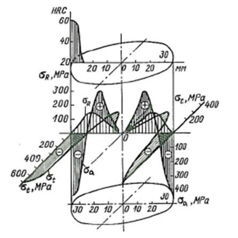
Traditional descriptions of residual stress distribution after surface induction hardening of a steel bar may be illustrated by Fig.1 [13]. It shows all three components of residual stress: radial, axial and hoop, as well as hardness distribution. In this typical case, radial stresses σr are much smaller than axial σa and hoop σt stresses. Hoop stresses are typically the strongest and they are mainly considered in analysis. In this case they have a maximum value of about 700 MPa (compressive) on the surface, drop to zero at the distance approximately corresponding to the case depth, change sign, reach a value of approximately 300 MPa (tensile) at half the radius and then drop to zero at the bar center. Tensile radial stresses may cause circular internal cracks, separating the hardened layer from the part core.
Stress evolution during heat treatment is a very complicated process and there have been no analytical methods to predict it accurately. Only experimental methods have been used for analysis. Experimental methods for determining stresses [14] include dissection, x-ray, neutron, or ultrasound, all of which are labor consuming and expensive. Also, they can be made only after the end of processing and important factors and effects that can occur during the process are being missed.
Development of internal stresses and distortions resulting from induction processing has a few root causes. In the block diagram of induction heat treatment process (Fig.2), stress and distortion blocks are at the end of a long chain of mutually coupled phenomena.
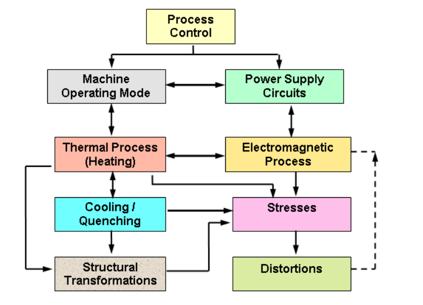
There are three types of stress sources –electromagnetic, thermal and structural. Stresses appear from the very beginning of heating due to thermal expansion of the surface layer and electrodynamic forces created by electromagnetic field on the part surface. Stresses and distortions due to electromagnetic forces are usually small compared to thermal and structural, and may be neglected except in the case of heating flat surfaces or long parts with a thin profile.
Computer simulation has been used for electromagnetic and thermal analysis for almost 40 years and has become a standard procedure for induction system design and optimization in recent years. There are multiple packages for induction system simulation. Fluxtrol, Inc. uses several programs from the relatively simple Elta to Flux 2D/3D Finite-Element package. In combination with structural analysis, using such program as Metal 7, computer simulation offers a less expensive and less time consuming method for tool and process development. Good accuracy of simulation and completeness of obtained information allows us to term this development procedure as “Virtual Prototyping of Induction Heat Treating” [15].
Simulation of stresses and deformation is an emerging technology, especially when dealing with induction, which started to be used for this purposes approximately 20 years ago [16-21]. Besides the variety and complexity of simulation algorithms, stress simulation requires large databases of thermal, metallurgical and mechanical properties of materials over the entire range of temperatures used during processing. In the present study the induction heating software Elta was used for electromagnetic and thermal simulation and the Dante package was used for thermal, structural, stress and distortion simulation.
Short description of simulation programs
Dante is finite element based software, which may be used for a complete analysis of a variety of heat treatment processes such as gear hardening after carburizing and furnace heating, quenching after furnace heating, etc. Dante has no electromagnetic block; therefore the combination with other programs is required for simulation of the processes that contain induction heating. The Dante software includes subroutines that mathematically describe the mechanical, thermal and metallurgical phase transformations that occur during heating and quenching of steel components so that phase fractions, hardness, dimensional change and residual stress can be predicted during the entire thermal treatment. Dante includes a database of steel alloys that cover the common carburizing and through-hardening grades of steel. It also includes data for surface heat transfer coefficients for more commonly used quenchants and quenching methods. References [22, 23] contain more detailed information on Dante.
Elta [24]is a program based on 1D Finite-Difference electro-thermal simulation of induction heating systems with analytical accounts for finite lengths of the part and induction coil. Elta has a database for electromagnetic and thermal properties of different materials and temperature-dependent heat transfer coefficients for a variety of quenchants.
Selection of case study
To minimize the number of variables and have the possibility to make a more or less general analysis of stress and deformation evolution during heat treatment, it was decided to select a case of OD and ID induction single-shot hardening of a thick walled tube. A 4140 steel tube with an outer diameter of 28 cm, inner diameter of 16cm and a length of 16 cm was heated uniformly by external (case 1) and internal (case 2) inductors. The heating and quenching processes were designed using Elta. The goal was to obtain a case depth of 6-7 mm with a maximum surface temperature of 1010 °C and a consistent heating time of 18 seconds. Under these conditions it was found that the hardness depth, corresponding to a temperature of approximately 800 °C, was 6 mm for ID heating and 6.8 mm for OD heating. A constant induction coil power regime was chosen. Process schedules are presented in Table 1.
| Step | Time, sec | Frequency, Hz | Power, kW | |
|---|---|---|---|---|
| OD | ID | |||
| Heating | 18.0 | 2000 | 580 | 352 |
| Hold | 3.6 | - | - | - |
| Spray Quench* | 100.0 | - | - | - |
| Air Cooling | 200.0 | - | - | - |
*12% PAGpolymer solution
Induction Hardening of Tube OD
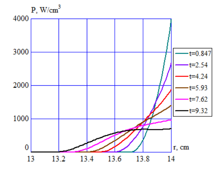
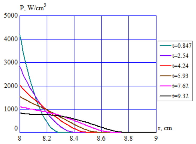
The outer diameter surface heating example was examined first. At present time it is not possible to transfer results directly from Elta simulation into the Dante program. The power distribution predicted by Elta was used in the Dante model for temperature, stress, displacement and hardness calculations. Volumetric power density curves for selected moments of heating time for OD heating are presented in Fig.3.
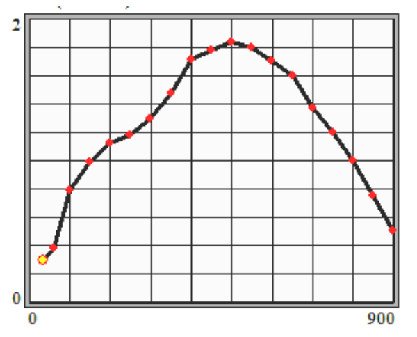
The heat transfer coefficient versus temperature used in simulation for spray quenching with a 12% PAG solution is displayed in Fig.4.
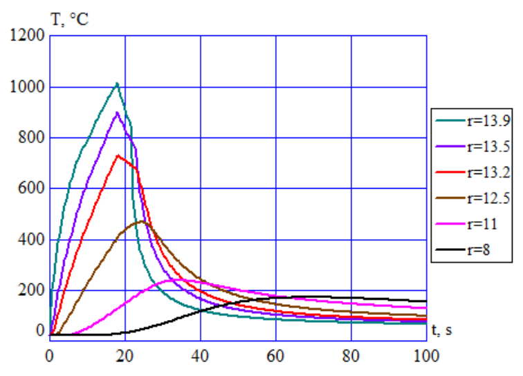
A history plot of temperature is shown in Fig.5 for specified radii. Temperature fields calculated by Dante and Elta (Fig.5) were very similar, which confirms accuracy of thermal blocks of both programs.
After 18 seconds of induction heating, the temperature at 1 mm below the OD surface has risen to over 1000 °C, while it is below 100°C at a distance of 30 mm. During the hold period of 3.6 seconds, the surface temperature dropped to 825 °C due to intensive heat soaking into the part body. At a depth of 8 mm, temperature remains approximately the same (620 °C) and at depths greater than 15 mm, temperature continued to rise as heat diffuses from the hot OD toward the cool ID of the tube. Spray quenching causes an immediate and rapid drop in the near OD surface temperatures, while the bore temperature continues to rise slowly before final cooling. This temperature behavior, typical for induction surface hardening, in combination with structural transformations creates a complicated evolution of stress distribution during processing.
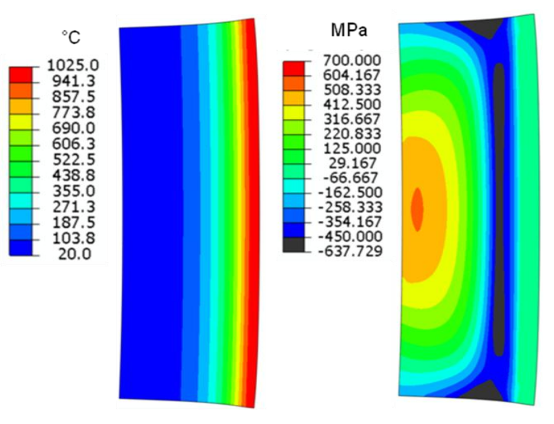
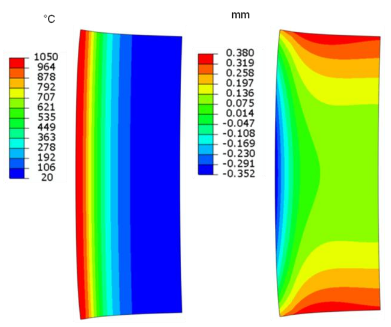
The temperature distribution map at the end of the heat cycle is displayed in Fig.6, along with the corresponding hoop stress distribution. A layer of compressive stress appears at a depth just below the region of formed austenite. As can be seen, the dimensional distortion due to thermal stresses is significant.
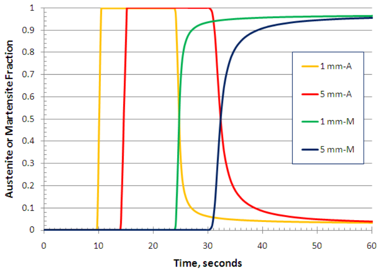
Fig. 7 shows almost instant austenite formation at the 1 mm and 5 mm depths during heating, and this austenite converts to nearly 100% martensite during spray quenching of the OD.
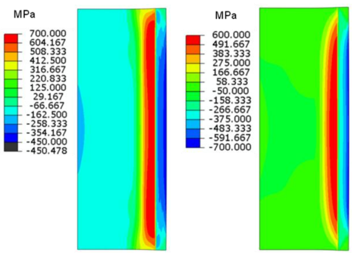
The final stress distribution after quenching and cooling is displayed in Fig. 8. A layer of compressive stresses is present roughly to the depth of the case. In spite of uniform heating and quenching along the tube length, both hoop and axial stresses are distributed along the tube non-uniformly. Compressive hoop stresses are largest in the central zone of the tube and much lower near the outer top and bottom edges. The compressive layer is immediately backed by a layer of significant tensile stresses at depths from 7 to 15 mm. The remainder of the body maintains a slight state of compression. Stress reduction near the ends of the part may be termed “Stress End Effect of the Part”. Distribution of axial stresses is similar to hoop stresses with greater end effect zone length and larger compressive stresses in the central zone compared to hoop stress values (700 MPa and 450 MPa correspondingly). It is worthy to mention that the part distortion is much lower than after the end of heating.
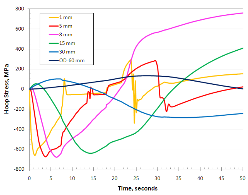
It is very important to analyze stress and distortion evolution during processing. Fig.9 shows the hoop stress evolution. Initially the tube OD is subjected to compressive hoop stress as the OD heats and its thermal expansion is restricted by the cold body of the tube. Considering the depth of 1 mm, notice how the stress starts to become less compressive after about 2 seconds. At about 10 seconds, evolution changes to an abrupt rise into the hoop tensile zone, followed by an equally abrupt drop back into the slightly compressive zone. The hoop stress' decline in compression after 2 seconds of heating is due to thermal expansion of the underlying material as it is being heated. At the 10 second point during heating, the abrupt rise in hoop tension is due to austenite formation (see Fig.7) in first the outer layer (depth lower than and equal to 1 mm), and the accompanying density increase associated with austenite formation. Once austenite starts to form at depths greater than 1 mm, there is the resultant drop in hoop tension in the outer layer, so the 1 mm depth remains under a slight compressive hoop stress for the remainder of the heating stage.
At the 21.6 second mark of the process, the surface is sprayed and the 1 mm depth location experiences hoop tension due to thermal contraction of the austenite. Soon after, upon martensite formation (Fig.7) and associated volumetric expansion of material, tension in the surface layer is relieved and hoop compression is experienced. From about 22 seconds to 34 seconds, the hoop stresses in outer layer are influenced by two factors: martensite forming at depths greater than 1 mm (leading to compression stress reduction) and overall thermal contraction of the tube (causing increase of compression stresses). As a result hoop stresses in outer layer become almost zero. After 34 seconds martensite formation is almost completed and the final thermal contraction of the tube (not in the range of the graph of Fig.9) takes place. Hoop stresses in the hardened layer become more compressive with a final value of -430 MPa at a depth of 1 mm after complete part cooling.
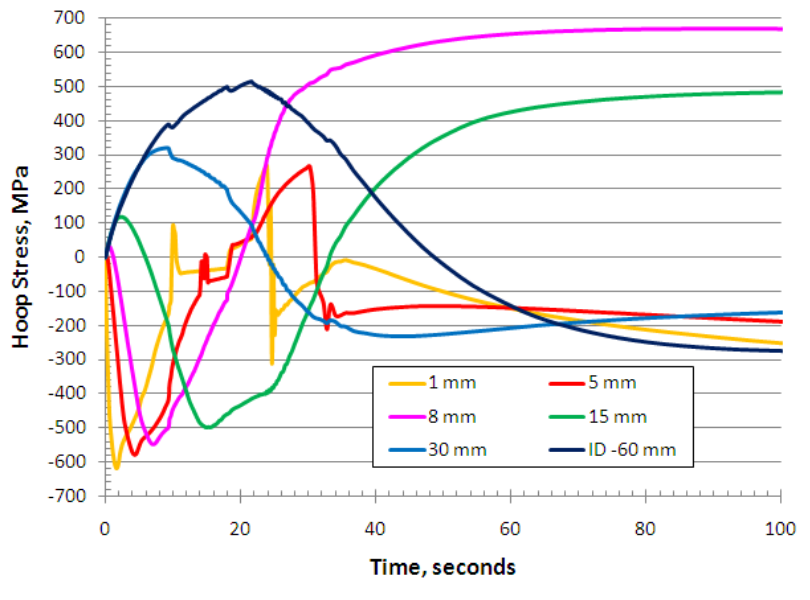
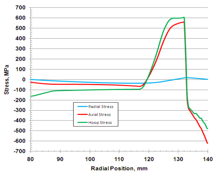
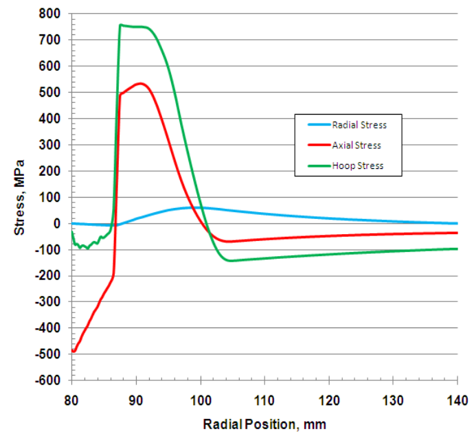
Fig. 10 shows the predictions for all three components of stress in the central plane of the part after complete cooling, i.e. residual stresses. Radial stresses are very small as expected and their influence on the part properties may be neglected. The distribution of hoop stresses corresponds in general to the traditional opinion (Fig. 1). Hoop stresses are compressive in the hardened layer and become tensile beyond the case, reaching values up to 600 MPa at depths 8-16mm. In the rest of the wall thickness there are moderate compressive hoop stresses around 100 MPa, which increase to 170 MPa on the ID surface. The axial stress distribution is similar to hoop stress behavior. It is interesting that on the ID surface, axial stress is stronger than hoop stress.
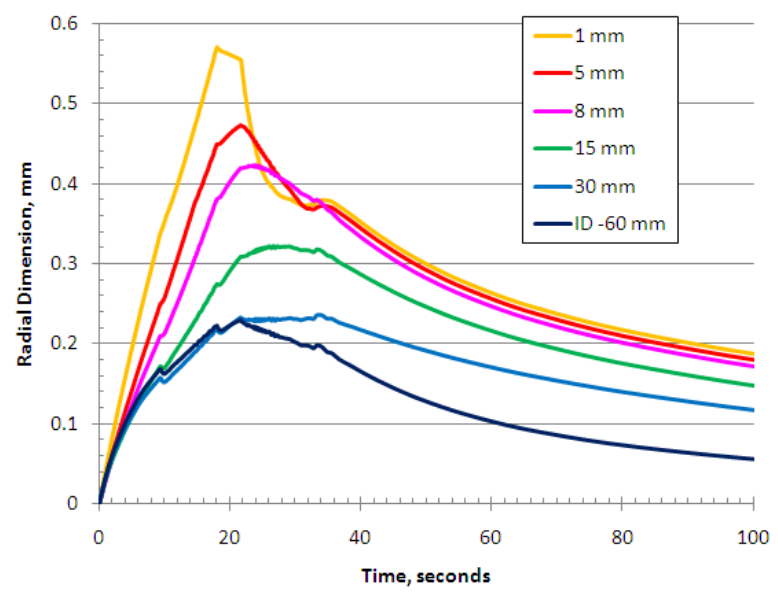
Evolution of the part distortion is also complicated and should be analyzed separately. The general character of deformation may be seen on Figs 6 and 8. After relatively large part deformation at the end of the heating stage, its shape returns nearly to initial dimensions with small distortion. Radial displacement evolution at different radii in the central plane is shown in Fig.11. The increase of the external radius reaches 0.55 mm at the end of heating and then goes down to a value of +0.003 mm at the end of processing (outside the range of the figure). Much larger permanent displacements occur near the tube ends.
Final radial and axial displacements at characteristic points of the part cross-section are given in Table 2. Axial position of the central plane is taken as zero. For OD heating, it is interesting that all radial displacements are negative except for an OD zone in the part center. Axial displacement on the OD is positive (part elongation) while on the ID it is slightly negative (part contraction). It means that there is a bending moment over the length of the part from the OD to the ID.
| Model | Location | Radial Displacement mm | Axial Displacement mm |
|---|---|---|---|
| Induction Heating of Tube OD | ID,
corners |
-0.040 | -0.002 |
| ID, center | -0.050 | 0.0 | |
| OD, corners | -0.061 | +0.113 | |
| OD, center | +0.003 | 0.00 | |
| Induction Heating of Tube ID | ID,
corners |
-0.065 | +0.072 |
| ID, center | -0.146 | 0.00 | |
| OD, corners | -0.061 | +0.002 | |
| OD, center | -0.058 | 0.00 |
Induction Hardening of Tube ID
Power densities at selected instances as functions of distance from the tube ID surface were taken from Elta (Fig. 11) and inserted into DANTE to predict residual stress and distortion. The distributions are very similar to those for OD heating with slightly higher power density values due to concave geometry causing the magnetic field and heat divergence in radius.
The temperature distribution map at the end of heating is displayed on Fig.13. Included with these results is the radial displacement map, which shows the greatest radius expansion within .35 mm at the top and bottom, and approximately the same contraction in the central ID zone. The ID layer experiences elongation causing external bending of the part cross-section.
The final stress distribution after quenching and cooling is displayed in Fig. 14. It is surprising that hoop stresses of the inner surface of the central zone of the part are almost zero while great compressive stresses occur at the top and bottom edges of the tube. This is in opposition to the effects seen in the surface compression layer for the OD heating case. Once again there is a layer with strong tensile stresses just beyond the case and slight compression in the remainder of the body.
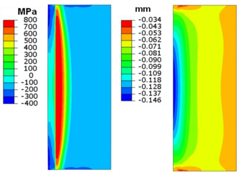
For tube ID hardening, both the bore and the OD are predicted to shrink in comparison to the starting dimensions. The radial shrinkage of the bore is predicted to be -0.146 mm and for the outer wall it is -0.058 mm. While the entire tube is predicted to shrink radially, the most significant shrinkage is at the tube ID center, and this is approximately two times the radial shrinkage at the tube ends. This is different than the radial dimensional changes for OD tube hardening (see Table 2). Similarly, the hoop stress evolution is considerably different for ID hardening than for OD hardening, comparing Fig. 15 to Fig. 9. The final hoop stress at 1 mm depth within the bore is only -84 MPa, while the final OD hoop stress is -98 MPa (out of range of figure).
This study demonstrates how much valuable information about mutually coupled electromagnetic, thermal, structural and mechanical processes may be obtained using computer simulation.
Conclusions
Internal stresses due to temperature variation and structural transformation during induction processing may be positive (shrink-fitting, bending strength improvement) or detrimental/negative (deformations, cracks, service properties reduction). In order to achieve the desired final properties of a material, the phenomena that occurs during the cycle needs to be understood and predictable. Residual stresses and part deformation after induction surface hardening depend upon many factors: part geometry, alloy chemistry and initial microstructure of the material, case depth, heating and quenching parameters. It is very difficult or even impossible to predict the interaction of all these factors by empirical methods alone. Computer simulation is a powerful tool for analysis of stresses and deformation evolution during the entire processing cycle.
This study of a thick-wall tube induction treatment using the Elta and Dante programs showed that the final stress distribution is different for ID and OD surface hardening. Hoop stress distribution along the part length is not uniform with stress concentration near the tube ends for ID hardening and in the central zone for OD hardening. Dimensional distortion of the part may be significant during the treatment process even if the final deformation is small.
Stress evolution shows a reversal behavior with a possibility of strong tensile stresses during the martensite formation, which can lead to quenching cracks. This effect is stronger for ID hardening than for OD hardening.
Computer simulation can predict stress and deformation evolution and provides a means for finding scenarios for control and optimization of heat treating and following surface finishing processes with an account for residual stresses. International networking is important for better understanding of evolution of stresses and distortions during induction heat treatment and improvement of tools for their prediction.
References
[1] V. Vologdin, Surface Hardening by High Frequency Currents, Metallurg, no.12, 1937
[2] Kontorovich and L. Livshits, Internal residual stresses induced in steel by high-frequency surface hardening, Metallurg, No. 8, 30, 1940 (in Russian)
[3] J. Grum, Overview of residual stresses after induction surface hardening. International Journal of Materials and Product Technology, Volume 29, no.1-4, 2007
[4] M. Lozinski, Industrial Applications of Induction Heating, Pergamon Press, Oxford, 1969
[5] G. Golovin, Residual Stresses and Deformation during High-Frequency Surface Hardening, Mashghiz, Moscow, 1962 (in Russian)
[6] S. Jahanian. Thermoelastoplastic and Residual Stress Analysis during Induction Hardening of Steel, Journal of Materials Eng. and Performance, V.4, Issue 6, 1995
[7] W. Dowling, et al., “Development of a Carburizing and Quenching Simulation Tool: Program Overview,” 2nd Int. Conference on Quenching and Control of Distortion, eds, G. Totten, et al., ASM Int., 1996
[8] C. Anderson, et al., “Development of a Carburizing and Quenching Simulation Tool: Numerical Simulations of Rings and Gears,” 2nd Int. Conference on Quenching and Control of Distortion, eds, G. Totten, et al., ASM Int., 1996.
[9] B. Liscic, Hardenability, in Steel Heat Treatment Handbook, edited by G. Totten and M. Howes, Marcel Dekker, NY, 1997
[10] J. Grum, Induction Hardening, in Handbook of Residual Stress and Deformation of Steel, edited by G. Totten, M. Howes, T. Inoue, ASMI, Materials Park, OH, pp 220-247, 2002
[11] R. Ivkov, S. J. DeNardo, W. Daum, A. R. Foreman, R. C. Goldstein, V. S. NeKudryavtsev, Internal Stresses as Resource of Strength in Machinary, M., Mashghiz, 1951 (in Russian)mkov, G. L. DeNardo (2005), Clin. Cancer Res, 11, 7093s-7103s
[12] N. McPherson, Induction heat straightening –A distortion rework reduction tool for thin plates, Welding and Cutting, 7, no.23, 2008
[13] V. Nemkov, R. Goldstein (2007), International Symposium on Heating by ElectG. Golovin, N. Zimin, Technology of Heat Treatment of Metals Using Induction Heating, L. Mashinostroeniye, issue 3, 1979 (in Russian)romagnetic Sources, Padua, 191-199
[14] www.fluxtrol.com Handbook of Measurement of Residual Stresses, Society for Experimental Mechanics, Jian Lu (Ed.): Fairmont Press, 1996
[15] R. Goldstein, V. Nemkov, J. Jackowski, Virtual Prototyping of Induction Heat Treating, Proceedings of the 25th ASM Heat Treating Society Conference, September 14–17, 2009
[16] D. Bammann, et al., “Development of a Carburizing and Quenching Simulation Tool: A Material Model for Carburizing Steels Undergoing Phase Transformations,” 2nd Int. Conference on Quenching and Control of Distortion, eds, G. Totten, et al., ASM Int., 1996
[17] W. Dowling, et al., “Development of a Carburizing and Quenching Simulation Tool: Program Overview,” 2nd International Conference on Quenching and Control of Distortion, eds, G. Totten, et al., ASM Int., 1996.
[18] H. Kristoffersen, P. Vomacka, Influence of process parameters for induction hardening on residual stresses, Materials & Design, Volume 22, Issue 8, December 2001
[19] P. Pacheco, M. Savi, A. Camara, Analysis of Residual Stresses Generated by Progressive Induction Hardening of Steel Cylinders, Journal of Stain Analysis, vol.36, no.5, 2001
[20] C. Gur, J. Pan, Handbook of Thermal Process Modeling of Steel, CRC Press, 2009
[21] C. Gur, J. Pan, Handbook of Thermal Process Modeling of Steel, CRC Press, 2009
[22] B.L Ferguson, A. Freborg, G. Petrus, M. Callabresi. Predicting the Heat-Treat Response of a Carburized Helical Gear, Gear Technology, December 2002
[23] Z. Li, A. Freborg, B. Ferguson, Application of modeling to heat treat processes. Heat Treating Processes, May/June 2008
[24] Elta (www.nsgsoft.com)
If you have more questions, require service or just need general information, we are here to help.
Our knowledgeable Customer Service team is available during business hours to answer your questions in regard to Fluxtrol product, pricing, ordering and other information. If you have technical questions about induction heating, material properties, our engineering and educational services, please contact our experts by phone, e-mail or mail.
Fluxtrol Inc.
1388 Atlantic Boulevard,
Auburn Hills, MI 48326
Telephone: +1-800-224-5522
Outside USA: 1-248-393-2000
FAX: +1-248-393-0277
Related Topics
- Stress and Distortion Evolution During Induction Case Hardening of Tube
- Modeling Stress and Distortion of Full-Float Truck Axle During Induction Hardening Process
- Effect of Steel Hardenability on Stress Formation in an Induction Hardened Axle Shaft
- Effect of Spray Quenching Rate on Distortion and Residual Stresses during Induction Hardening of a Full-Float Truck Axle