


Authors: Sean M. Muyskens, David R. Morris, Christopher J. Yakey and Robert C. Goldstein
Location/Venue: HES 2023 Padua, Italy
Induction tube welding systems utilize an internal magnetic flux controller (impeder) to improve process efficiency. Work has previously been done showing that soft magnetic composite (SMC) materials may be suitable to improve these systems. A test stand was devised for the physical simulation of SMC impeder performance for use in induction tube welding systems. Tests were run to determine the loading and cooling conditions in which an impeder core made of SMCs could survive. Additionally, 2D thermal simulations were run to determine the cooling system thresholds given a particular magnetic loading of the core. The goal of these tests was to expand the design envelopes in which impeder cores made of SMCs could survive and validate their use in induction tube welding systems.
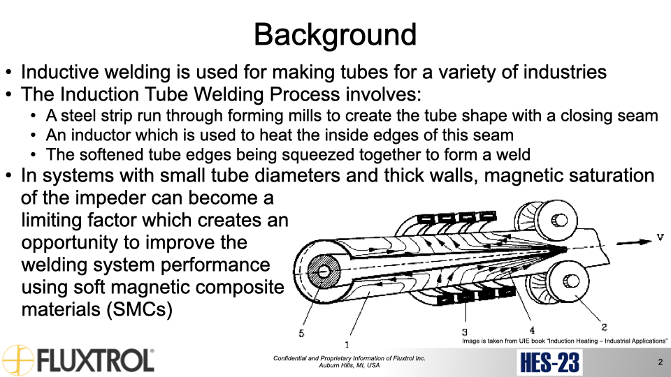
Inductive welding is a popular method for making tubes used in a variety of industries. Over the past 20-30 years, the industry has been transitioning from tube generators operating at 400 kHz to solid state generators (either IGBT or MOSFET) which operate at 50 kHz to 400 kHz. The availability of high power at lower frequencies has created the opportunity to successfully weld larger tubes with greater wall thicknesses for more demanding applications. At the same time, one of the key components of the system, the impeder, has not changed significantly, which is limiting the production rate or resulting quality of some types of tubing.
Impeders are typically manufactured using a combination of constructive elements and ferrite rods or tubes (ferrites). Ferrites have a low saturation flux density which is strongly temperature sensitive, are limited in size and availability, and are very susceptible to mechanical and thermal shock. The saturation flux density becomes more of an issue for lower frequencies, where the desirable flux density for welding is higher. This new situation creates an opportunity to improve the welding system performance using SMCs [1]-[2].
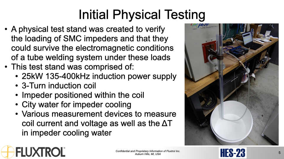
At HES 19, a hybrid simulation method utilizing 2-D and 3-D coupled models was used for the study, design, and optimization of the tube welding process. The models incorporated magnetic flux controllers and quantified their role in improving the welding process. A comparison was made between impeders using SMCs and those made with traditional ferrites for use in typical tube sizes [3]. Based on this initial computational modeling, a physical test stand was created to verify the loading of SMC impeders and that they could survive the electromagnetic conditions of a tube welding system under these higher loads [4]-[5].
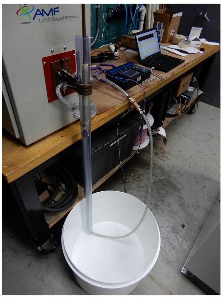
Fig. 1 shows an initial prototype of a test stand that was constructed to carry out these tests. The major components of the test stand were a 25kW power supply capable of 135-400kHz, a three-turn induction coil, an impeder positioned within the coil, city water to cool the coil which emptied into a tank, and various measurement devices to capture the coil current, voltage, and inlet and outlet temperature of the cooling water from the impeder. Trials consisted of running impeders of various materials and sizes for one hour in this setup. The material tested included Fluxtrol A, Fluxtrol 50, Fluxtrol 75, Ferrotron 559H, and Ferrotron 559 Original, and the sizes tested were 10, 12, 14, and 19mm standard impeder sizes [4],[6]. The power supply was adjusted for each trial until the maximum tunable operating power was achieved without hitting any faults or limits. Losses were calculated calorimetrically using the difference in inlet and outlet water temperature and the flow rate. This value was then compared to predicted values using magnetic flux densities from 2D magnetic simulations and loss data for each material. Impeder inductance and resistance were measured before and after trials to detect any difference in impeder electromagnetic characteristics that may have been caused during the trial as a sign of degradation.
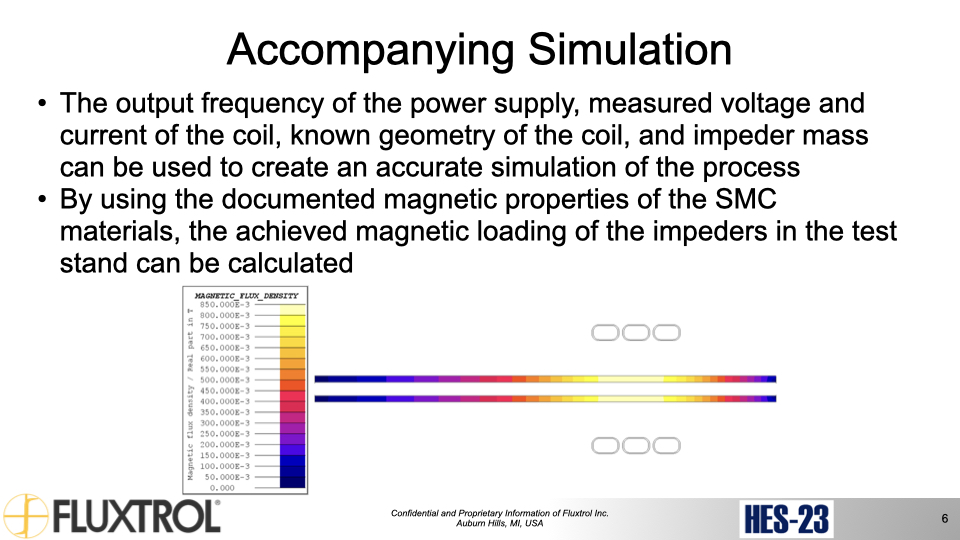
Computer models were used to calculate the flux density in the impeder based on experimental measurements. The output frequency of the power supply, measured voltage and current of the coil, known geometry of the coil, and impeder mass can be used to create an accurate simulation of the process. Fig. 2 shows a 2D axisymmetric simulation for a 12mm impeder made from Fluxtrol A for one of the test conditions run on this test stand. While the flutes cannot be modeled in this way, by using the mass of the impeder and density of the Fluxtrol A, an equivalent amount of material is modeled. This method should be acceptably accurate because at the area of interest in the center of the impeder, the material is quasi-linear and of a moderate level of magnetic permeability, the flux density is unidirectional in the area of highest loading, and there is a large airgap between the coil and the impeder [7].
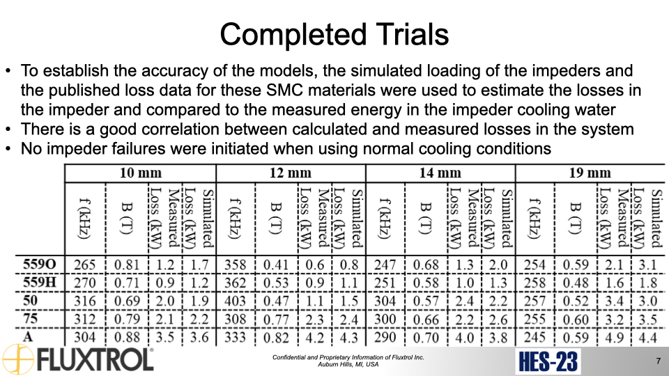
By using the documented magnetic properties of the SMC materials, the achieved magnetic loading of the impeders in the test stand can be calculated. After gathering enough data points for survivable loading of the impeder an experimentally validated operational window can be generated. These results can be confirmed by using this calculated loading, as well as the published loss data for these SMC materials to estimate the losses in the impeder and compare that to the measured energy in the impeder cooling water. The results showed a good correlation between calculated losses and measured losses in the system as seen in Table 1. This work was expanded upon and presented at IMAT 2022 [5],[8].
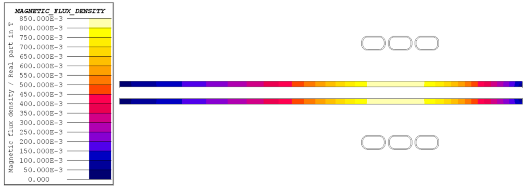
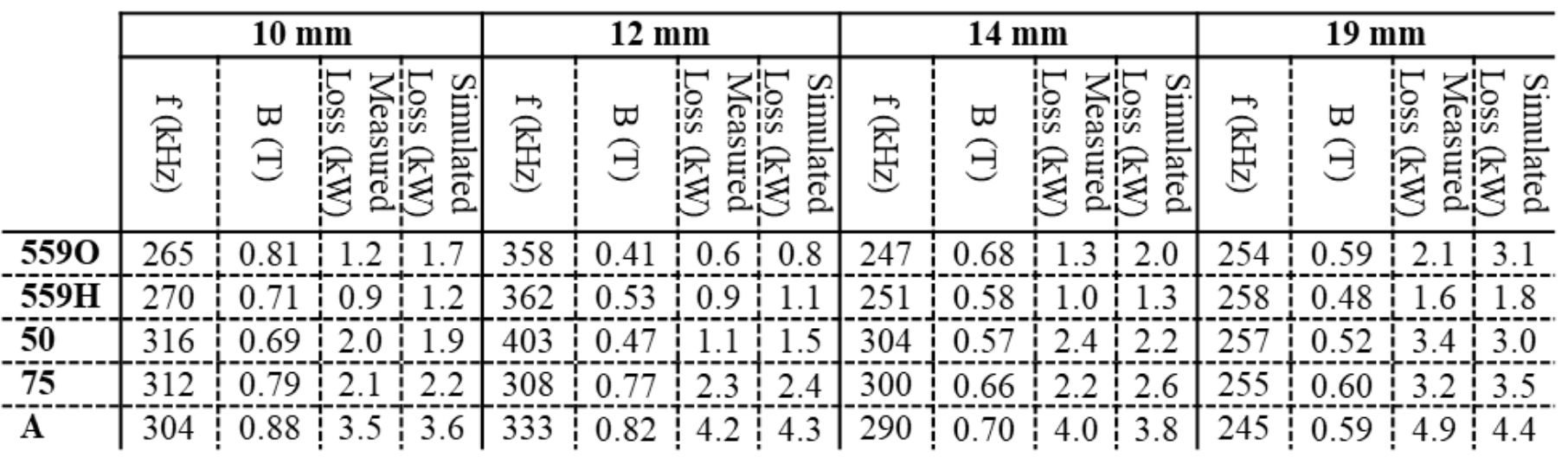
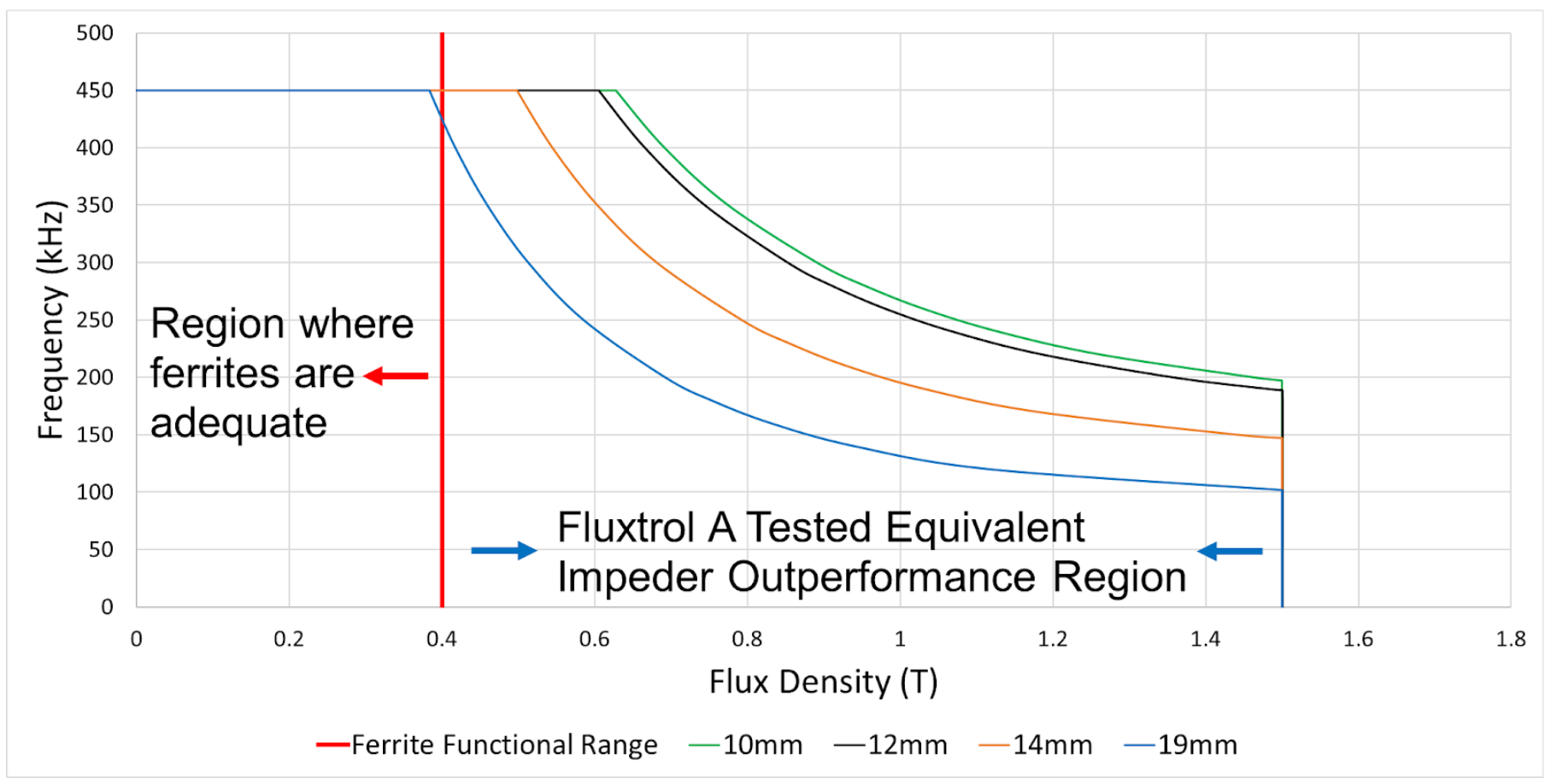
Fig. 3 shows the operational window for Fluxtrol A impeders created based on the results of the run trials. The red line signifies the saturation flux density for common ferrites [6]. For magnetic loading less than this value, induction tube welding systems would not show much benefit from a switch to an impeder constructed with an SMC. For magnetic loading greater than this value, induction tube welding systems are potentially facing an induction bottleneck. At saturation the impeder core cannot carry further magnetic load, meaning as the power is turned up, the current may start to diverge from the weld vee, so the process becomes less efficient, and the line speed will increase at a much lower rate than power. This is the area of opportunity for SMC materials, as the saturation flux density of Fluxtrol SMCs under consideration is approximately 2 to 3 times that of ferrites used for tube welding [6]-[7]. Each line represents various sizes of impeder made of Fluxtrol A and shows validated points of loading where the impeder will survive provided 20°C water at 40PSI. The area under each of these lines and to the right of the ferrite saturation is where a switch to an impeder made of Fluxtrol A will help to improve the system performance.
During the initial trials with the original test stand, we were not able to reach a magnetic loading where the impeder failed within one hour provided moderate cooling. There were several limits experienced during that testing that prevented us from reaching these conditions based on the power supply, coil, and cooling system. The goal of this study is to determine the point at which SMC impeders are expected to experience thermal failure due to magnetic loading and to verify these values using physical simulation.
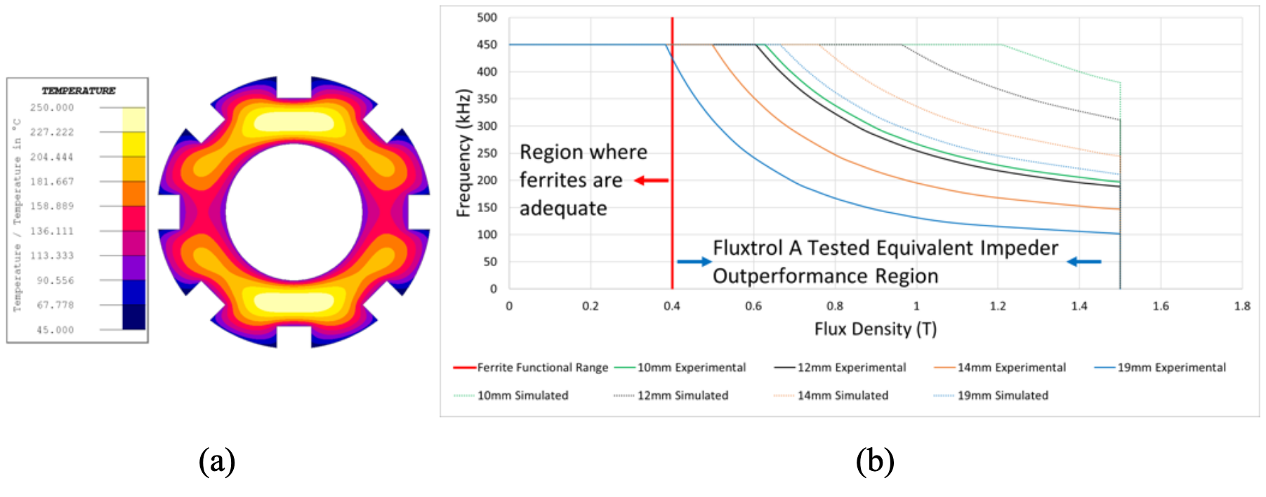
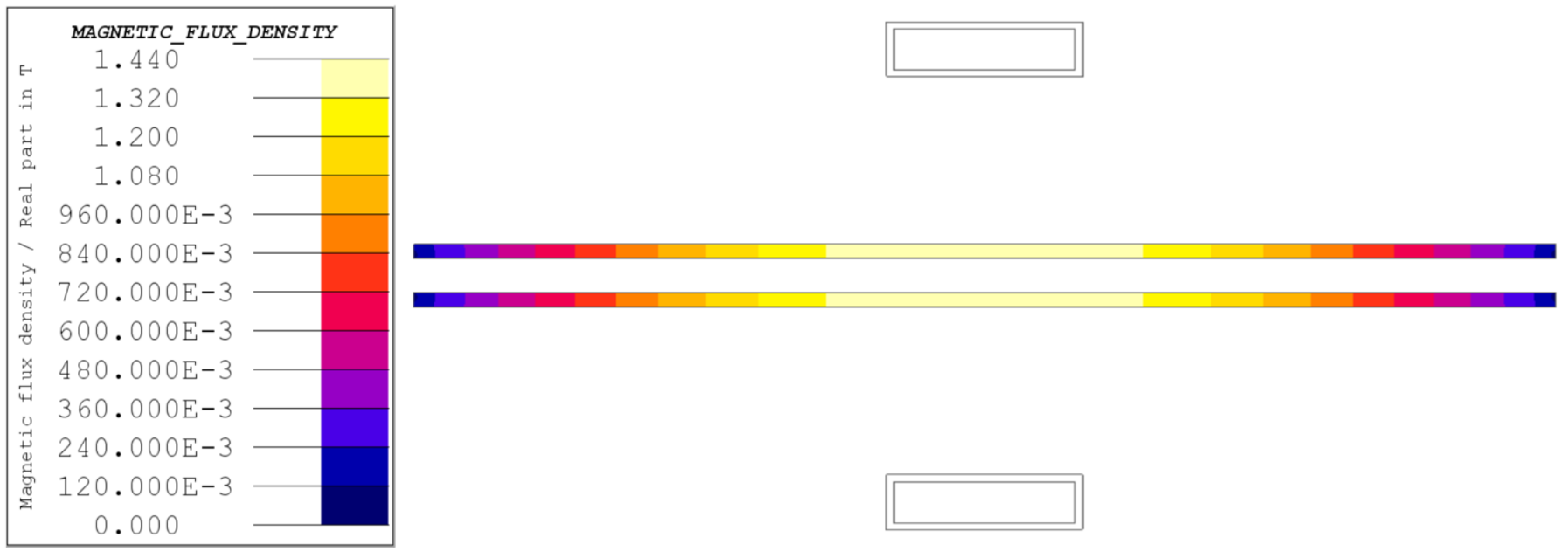
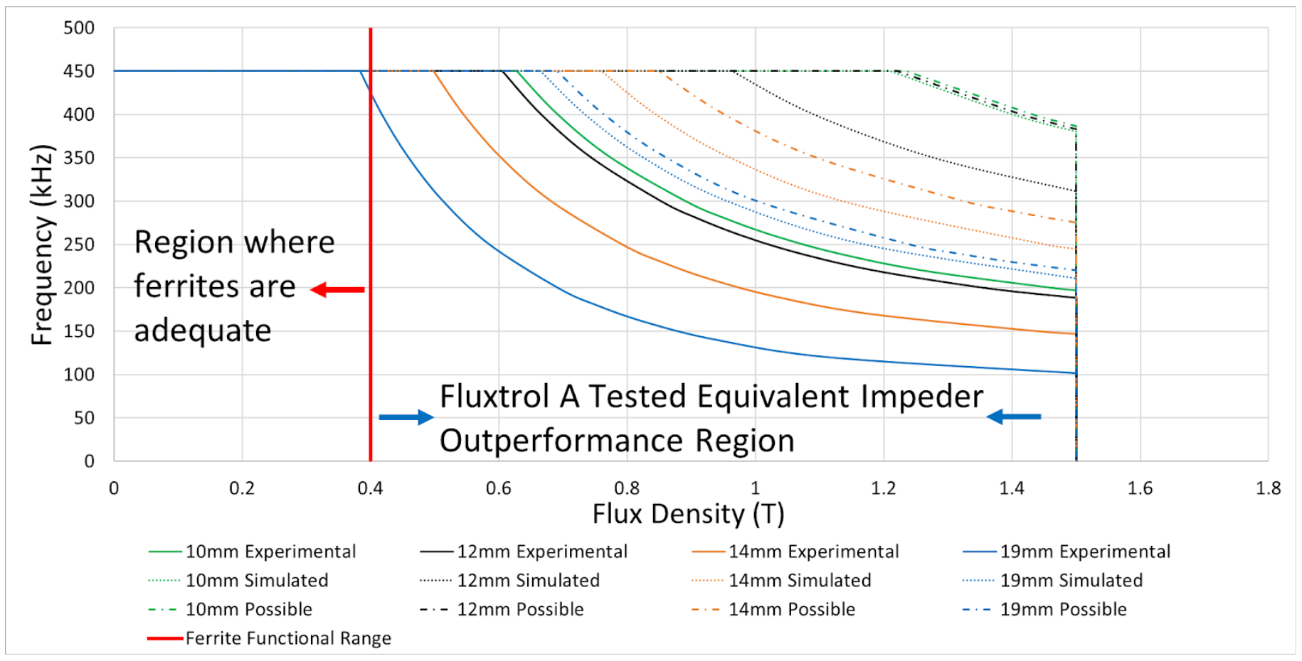
The original test stand was incapable of delivering sufficient magnetic loading to test SMC impeders to failure and determine the full operation envelope they would be capable of. To determine what improvements needed to be made to the test stand, the theoretical thermal limits of the impeders needed to be calculated in order to find a target loading the new test stand should be able to supply. To this end, 2D thermal simulations were performed to investigate what theoretical limit of impeders made of SMC materials could survive provided cooling like that experienced in a tube mill [6]. Based on initial trials, the cooling boundary was set to a convection coefficient of 30000W/m2K with an average cooling water temperature of 40°C. The loading of the impeder was increased until the steady state operating temperature of the impeder exceeded 250°C which is the published long-term operating temperature for these materials. [7] Fig. 4 (a) shows a cross-section of a 12mm Fluxtrol A impeder with loading equivalent to 1.4T at 400kHz. Fig. 4 (b) shows the theoretical limits for each size of impeder and how it compares to the experimentally validated range. Computer simulation predicted that the tested impeders could survive with significantly higher magnetic loading than was tested for all conditions. These results agree well with the experimental test data.
The initial trials with the original test stand were successful in demonstrating that the SMC impeders would operate at magnetic loading levels above the saturation flux density of ferrites, validating the working theory to explain the large energy and productivity savings from field testing [5]. The results also showed that we could model the test system and calculate the conditions under which the impeder was being tested with reasonable accuracy. However, we were not able to reach one of our test goals, which was validating the point at which the SMC impeder would fail thermally due to magnetic loading. There were several limits experienced during that testing that prevented us from reaching these conditions based on the power supply and coil design.
Besides the capability to reach failure, another challenge with the initial test stand was the accuracy and precision of the measurements. Generally, measurements with higher calorimetric losses showed reasonable agreement around ±10% with the calculated values. However, at lower levels of losses, the error tended to be much higher. These deviations also tended to be larger for lower permeability materials. It is unclear if these differences are due to measurement error in the system or simulation error.
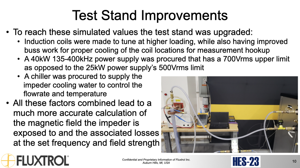
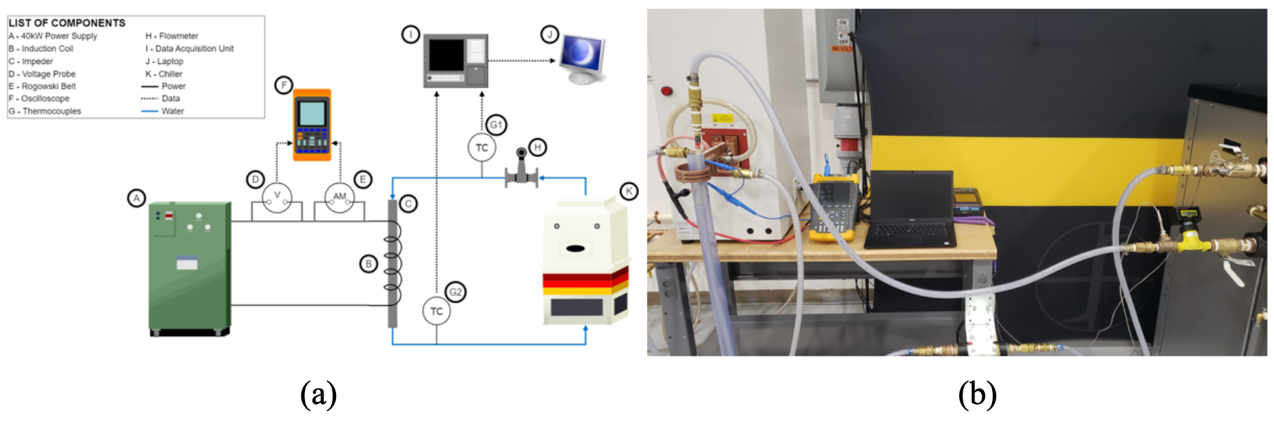
Fig. 5 (a) is a conceptual diagram of the new test system and Fig. 5 (b) shows the revised test stand with various improvements to the available control and measuring of the process. To avoid the limits of the previous 25kW power supply, a 40kW 135-400kHz power supply was procured with higher voltage capability (700 Vrms as opposed to 500 Vrms). Besides increased output voltage, the new power supply has an upgraded control board and increased inverter current capability to help the unit accommodate non-linearities to the waveform caused by the magnetic core under high magnetic field strengths. The coil busbar was engineered to allow for easy hookups and reduce the exposure of the Rogowski belt and voltage probes to fields from the winding to reduce unintended heating and improve measurement accuracy.
To improve the control of water flow through the impeder and more accurately track the change in temperature from the inlet and outlet, a separate, closed loop, controllable chiller unit was installed. With the unit and new flow valves installed it is possible to set and monitor a stable water temperature, pressure and flow rate for the impeder during trials. All these factors combined lead to a much more accurate calculation of the magnetic field the impeder is exposed to and the associated losses at the set frequency and field strength.
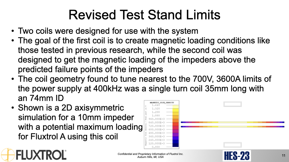
Two coils were designed for use with the system. The goal of the first coil is to create magnetic loading conditions like those tested in previous research. Additional trials could be used to verify the new system performance and determine the source of the error in the previous trials. This coil designed for these tests had 3 turns, an ID of 70 mm and a length of 34 mm.
The second coil was designed to get the magnetic loading of the impeders above the predicted failure points of the impeders. The coil geometry found to tune nearest to the 700V, 3600A limits of the power supply at 400kHz was a single turn coil 35mm long with an 74mm ID. This coil and electrical parameters were run for each size of impeder and Fig. 6 shows a 2D axisymmetric simulation for a 12mm impeder with a potential maximum loading for Fluxtrol A with this coil.
The testing procedure is as follows. A replacement impeder core made of an SMC is manufactured and its dimensions, weight, and magnetic response in a known solenoid are measured. It is placed in an impeder casing designed for the equivalent ferrite. This impeder casing is plumbed in series with a chiller to control the flow and incoming temperature of the impeder cooling water. A flowmeter and two in-line thermocouples monitor the flow and change in temperature at the inlet and outlet to the impeder. The impeder casing is centered in the induction coil to apply the magnetic field. An oscilloscope, voltage probe, and Rogowski belt are used to monitor the voltage and current in the coil to later calculate the magnetic field generated. The power supply is tuned to the desired frequency for the test and turned on to low power. The process is given 10 minutes to equalize and assure the impeder has not failed and the power is increased incrementally. This process is repeated until one of the following occurs:
In the case of conditions 1 or 2, the test will be run until either the planned run time of the test is achieved, the machine faults or condition 3 occurs. After completion of the test, the impeder core is removed from the system, inspected visually for damage, and once again its dimensions, weight, and magnetic response are measured. The measured data for the system at the interval prior to failure can then be used to calculate the magnetic field at which an impeder of this size and material was operating successfully and additional trials will be planned around this condition to better define the impeder design capabilities.
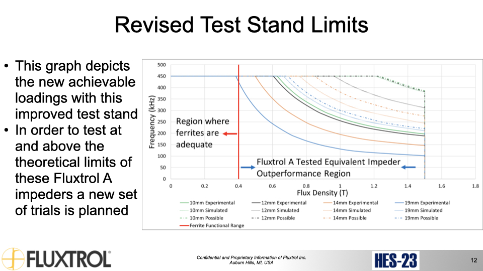
While there will be a significantly higher voltage drop in the leads and components prior to the coil head when coil current is highest (smallest impeders), an estimate of achievable impeders loadings can be made with these results. Fig. 7 depicts the new achievable trials with this improved test stand. In order to test at and above the theoretical limits of these Fluxtrol A impeders a new set of trials is planned.
The size of the impeder to be tested was limited to sizes under 1” in diameter, as the tube welding systems operating with this sized component are most likely to be in a state of saturation of the impeder, in which a shift to a higher saturation flux density material would be beneficial. Based on commercially available sizes, the impeders sized run in the currently planned trials is 10mm, 12mm, 14mm, and 19mm. Each SMC impeder would be machined to be a copy of the commercially available ferrite to offer an apples-to-apples comparison. The impeders tested were all made of Fluxtrol A, as previous testing made it clear that this material is capable of withstanding the highest loading due to its high saturation flux density and reasonable losses and thermal characteristics.
Soft magnetic composite impeders have shown the potential to significantly improve the performance of inductive tube welding systems where the ferrite impeders being used are in saturation. This is a common occurrence in small diameter tube welding installations. Previous studies were conducted using a combination of computer simulation and physical simulation to model the system performance and identify the operational performance limits of soft magnetic composite impeders. These earlier studies showed that the soft magnetic composite impeders could survive with saturation flux densities exceeding the saturation flux density of ferrite impeders at typical tube welding frequencies. The drawback of the earlier studies is that they were not able to identify the upper limit of where the materials could perform. There were also varying degrees of correlation between the measured and calculated values for magnetic losses under some conditions.
In order to better understand the upper bounds of operational capability for soft magnetic composite impeders, computer simulation was conducted to predict the upper bound of performance for 10, 12, 14, and 19mm impeder cores constructed from Fluxtrol A. Using these experimental test requirements, computer simulation was used to design an induction coil that would achieve test levels in excess of the predicted performance limits using an upgraded induction heating power supply. Besides the induction heating power supply, the water cooling system and measurement capabilities were also improved on the test installation.
The upgraded test stand has been recently constructed and further trials to expand the operational window of impeders made of SMCs will be conducted in 2023. The results of the experimental measurements will be used to improve the accuracy of the computer models. Future work is also planned to improve the impeder design to further expand the operational windows of the material compared to the traditional fluted impeder design.
[1] Goldstein, R.C. (2014). Magnetic Flux Controllers in Induction Heating and Melting. ASM Handbook Volume 4C, 633-645.
[2] Nemkov, V. (2008). Magnetic Flux Guide for Continuous High Frequency Welding of Closed Profiles. US Patent Application, US20080308550A1.
[3] Muyskens, S., Eddir, T., Goldstein, R. (2019), “Improving Induction Tube Welding System Performance Utilizing Soft Magnetic Composites”, HES19, Padova, IT
[4] Muyskens, S., Goldstein, R. (2021), “Physical Simulation of Soft Magnetic Composite Impeder Performance for use in Induction Tube Welding Systems”, UIE Congress, Pilsen, CZ
[5] Muyskens, S., Goldstein, R. (2022), “Physical Simulation and Computational Modelling for Validation of Soft Magnetic Composite Impeder Performance”, IMAT 2022, New Orleans, USA
[6] EHE Consumables. (2019). Product Catalog. EFD Induction Group
[7] Fluxtrol Inc. (2023). https://fluxtrol.com/soft-magnetic-materials. Fluxtrol Inc.
[8] P. Vaishnava, R. Goldstein, (2019), Magnetic Core Loss Behavior at High Magnetic Fields in Magnetic Materials, HES 2019 Conference, Padua, IT.
Our knowledgeable Customer Service team is available during business hours to answer your questions in regard to Fluxtrol product, pricing, ordering and other information. If you have technical questions about induction heating, material properties, our engineering and educational services, please contact our experts by phone, e-mail or mail.
Fluxtrol Inc.
1388 Atlantic Boulevard,
Auburn Hills, MI 48326
Telephone: +1-800-224-5522
Outside USA: 1-248-393-2000
FAX: +1-248-393-0277