Information
Authors: V. Nemkov, R. Ruffini, R. Goldstein, J. Jackowski, T.L. DeWeese and R. Ivkov
Location/Venue: HES 10/COMPEL Padua, Italy
Topic: Cancer Treatment
Abstract
The purpose of this paper is to continue studies previously reported with the primary focus of optimizing an inductor design. The potential benefits of hyperthermia for cancer therapy, particularly metastatic cancers of the prostate, may be realized by the use of targeted magnetic nanoparticles that are heated by alternating magnetic fields (AMFs).
Introduction
The potential therapeutic benefits of hyperthermia (42-468 C) for cancer therapy are well described (Overgaard, 1985; Streffer and Van Beuningen, 1987). However, progress to the clinic has been impeded by technical difficulties of selective heat delivery to the target tissue without overheating adjacent normal tissue. Magnetic nanoparticles have given new impetus to this research. When exposed to alternating magnetic fields (AMFs), they generate heat from several potential mechanisms (DeNardo et al., 2007). In recent years, both untargeted and targeted nanoparticles have been used in cell cultures, animal models and even in clinical trials (DeNardo et al., 2007; Johannsen et al., 2007). Particularly promising is a targeted nanotherapy, where the nanoparticles are attached to specific molecules enabling them to bind to the cancer cells (DeNardo et al., 2007, 2005; Gruettner et al., 2007; Natarajan et al., 2008; Lehmann et al., 2008). Intravenous administration of targeted magnetic nanoparticles for heat delivery offers significant potential to address metastatic cancers, such as prostate cancer (Lehmann et al., 2008). These “smart” nanoparticles can bind selectively to metastatic tumors to deliver a cytotoxic dose of heat. The amount of heat delivered to the targeted cells or tissues depends upon:
- the particle concentration and distribution at the cell/tissue;
- the normalized power loss of the particles (i.e. heat produced at a given fieldamplitude); and
- the frequency and amplitude of the AMF (DeNardo et al., 2007).
The latter requirements are particularly important for device design. It has been established that the appropriate AMF frequency range is 100-200 kHz for these applications to minimize non-specific heating of tissues and stimulation of nerves by induction, while producing reasonable heat output from the particles (Adair and Black, 2003; Ivkov et al., 2005; Dughiero and Candeo, 2008). Since the power losses of the particles are field amplitude-dependent, a uniform flux density is needed to ensure consistent and predictable heating in the volume of interest.
To further explore the potential of this technology, and to define the specifications necessary for clinical translation, we require data obtained by heating cancer cells treated with labeled magnetic nanoparticles. Initially, the method for doing so was to supply a uniform magnetic field to an individual cell culture sample or a small animal such as a mouse. The development has progressed to multi-cell data acquisition using multi-well dishes. A high-throughput device capable to accommodate multi-well dishes is needed for this research effort. Further, this device must provide temperature control that is suitable for cell culture experiments (within physiologic limits) with continuous duty operation for more than 1 h. This will ensure that the only heat stress on the cells originates from the nanoparticles and not from thermal losses of the device. The inductor needs to sustain low temperatures not only for the reliability of data but also to prevent degradation of the inductor for a long life cycle. These requirements place significant design challenges to mitigate the significant thermal consequences of the inductor. Once the challenges have been overcome, further advancements can be made in this technology leading to appropriate pre-clinical and clinical development.
Possible solutions
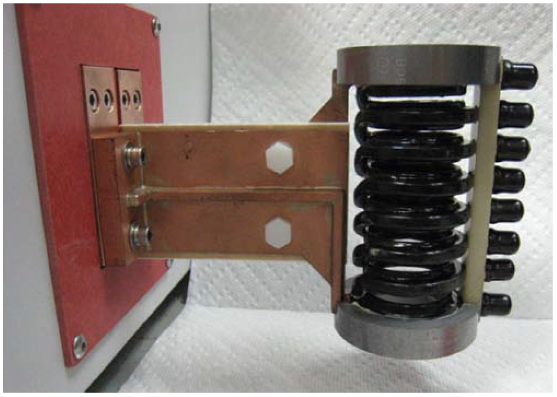
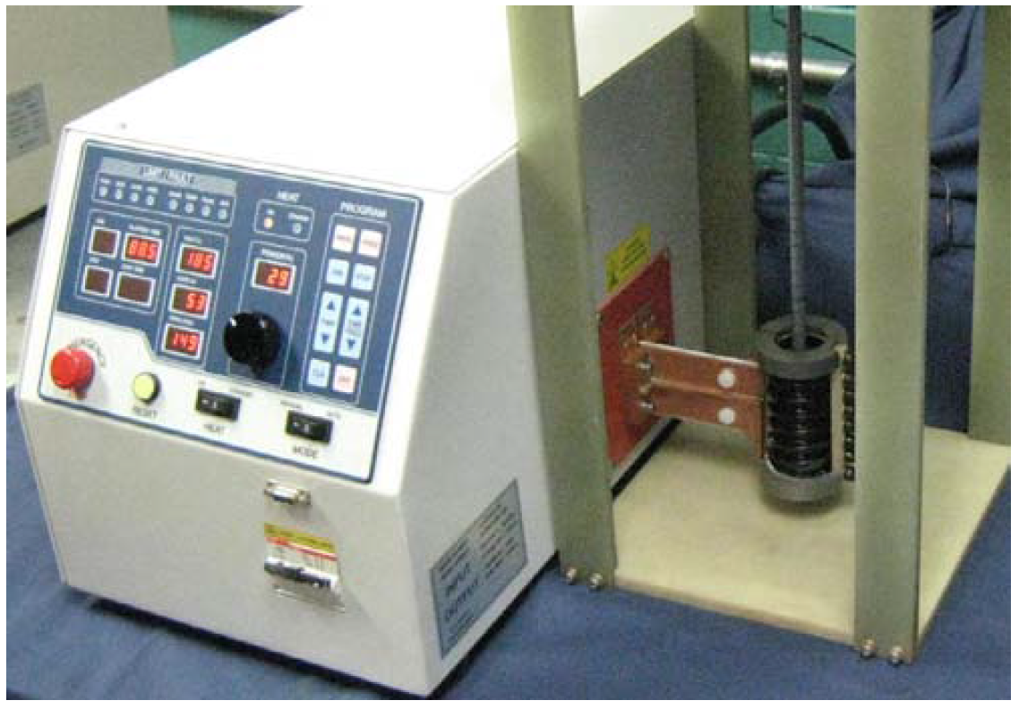
Solenoid coils are the traditional inductor geometry used for individual cell cultures or small animals. These coils provide a uniform magnetic field in limited volume within the coil, exposing samples to 3D field amplitude variations. Power losses from magnetic nanoparticles are field amplitude dependent, so it is impossible to control the deposited heat dose, a critical variable for thermal therapy. To overcome the deficiencies of traditional solenoids, modifications were considered to improve the field distribution within the coil (Figure 1). One improvement is realized by wrapping the turns in plane, keeping the junctions between each turn aligned along the same path. This creates a more uniform magnetic field by eliminating geometrical variation of the circumference of the coil. Additional control of the field distribution is gained by adding a ring comprised of low-reluctance material to each end of the coil. These rings act as magnetic concentrator caps on each end of the coil to help homogenize the field distribution inside the coil and decrease the current demand and lower the reactive power. Solid leads to the connection of the power source were designed and fabricated to reduce their influence on the field in the test area. These improvements produce significant gains in control of the field distribution inside the coil when compared against a traditional solenoid. Figure 2 shows the entire testing system during the operation of measuring magnetic field along the center line of the coil.
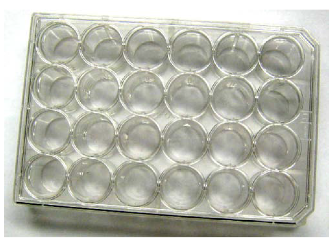
High-throughput biological testing places demands on AMF equipment specifications to accommodate multi-well sample chambers of containers. A common type of container is the multi-well plate or sample dish having a standard size of 86 mm x 127 mm x 19 mm with 16-96 wells or chambers for growing cells or containing sample (Figure 3). The experimentally relevant area of the dish is approximately 80 mm x 120 mm (or 96 cm2). The desired maximum magnetic field amplitude for our tests is 31.8 kA/m, with a^10 percent tolerance for field variation within the 100-cm2 area defined by the dish. The primary frequency chosen for the studies is 150 kHz. The temperature of the inductor surfaces contacting the sample dish are to be maintained between 35 and 398 C during a continuous duty cycle lasting up to 1 h.
The Helmholtz coil geometry overcomes many of the challenges posed by the specifications. However, Helmholtz coils require considerable reactive power to generate large-amplitude fields at the desired frequency. Since the sample dish is rectangular, it is necessary to consider the largest linear dimension as the diameter for uniform field distribution, 130 mm at the diagonal.
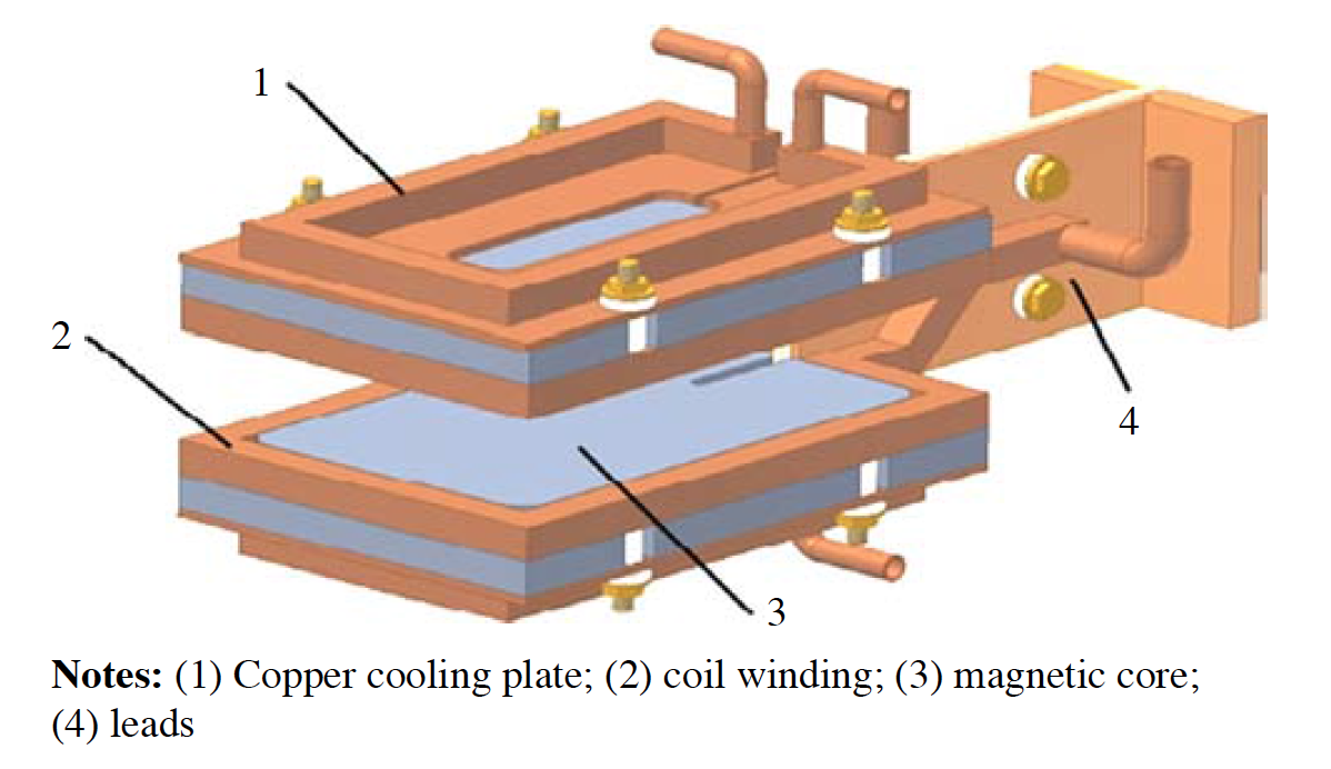
We consider a rectangular coil with magnetic core (Figure 4) as a viable design that provides the necessary performance. With this style, it is possible to achieve a zone of uniform magnetic field strictly in the volume occupied by the cell cultures. The key dimension for this is the width of the dish, 80 mm.
Design and simulation procedure
For calculation of magnetic field distribution for the Helmholtz coil, Flux 2D computer simulation program is used and the system is assumed to be axisymmetrical. In reality, field strength levels will be more non-uniform than simulation shows due to the leads area of the coil. To compensate for this in the coil optimization, the dimensions of the Helmholtz coils were adjusted until the magnetic field strength in the area of interest was 31.8 kA/m^2.5 percent.
For calculation of magnetic field distribution for the rectangular coil with magnetic core, Flux 2D and Flux 3D computer simulation programs are used. For the preliminary coil design, the system is assumed to be plane parallel. The dimensions of the rectangular coil are adjusted in 2D until the magnetic field strength in the dish area is 31.8 kA/m^2.5 percent. For final coil optimization, 3D simulation of one-eighth of the system was used to account for the corner area and cross-legs. The coil depth, or plate separation was adjusted with 3D calculations to achieve the desired uniformity of 31.8 kA/m^10 percent.
Electromagnetic results
The dimensions of the Helmholtz coil needed for generation of uniform magnetic field in the required area were calculated, which are quite large (radius of turns is 111 mm). Correspondingly, voltage, current, active power and reactive power are all large (Table I).
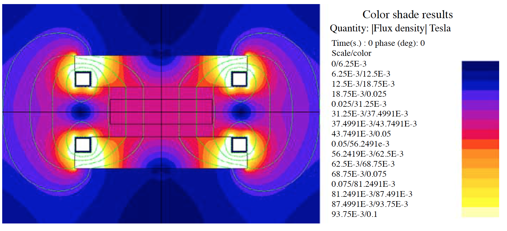
Figure 5 shows the magnetic flux density distribution and magnetic field lines for the rectangular coil from 2D simulation. Fluxtrol 50 was initially selected as the magnetic core material. The dimensions of the coil are significantly smaller than for the Helmholtz coil (length = 11 cm, h = 4 cm). Correspondingly, voltage, current, active power and reactive power are all reduced dramatically (Table I).
| Coil type | Core | Program | Bm (Gs) | U (V) | I (kA) | S (MVA) | P (kW) |
|---|---|---|---|---|---|---|---|
| Helmholtz | None | Flux 2D | 400 | 1,750 | 8.4 | 14.7 | 74 |
| Rectangular | Fluxtrol 50 | Flux 2D | 400 | 650 | 3.8 | 2.5 | 24 |
| Rectangular | Fluxtrol 50 | Flux 3D | 400 | 720 | 3.3 | 2.4 | 26 |
| Widened cross-leg | Fluxtrol 75 | Flux 3D | 400 | 660 | 3.5 | 2.3 | 25 |
Then, the electrical parameters of the coil were calculated using 3D simulation, which agree well with the results of 2D simulation and are presented in Table I. Coil voltage is slightly higher and coil current slightly lower for the 3D case. This could be expected, as current flowing in the cross-over leg will lead to a higher voltage requirement, but also contribute to flux in the dish area, reducing current demand.
Thermal management techniques and results
Tests of the rectangular coil revealed significant component heating, especially for the magnetic core. An additional study using thermal simulation of the induction coil components was done (Nemkov and Goldstein, 2007) relating to preventing cell culture exposure to external temperatures in excess of 398 C. Many thermal management techniques were purposed and explored. The major available options are as follows:
- heat extraction through water cooling;
- concentrator material selection/orientation for reduced losses and better heat transfer;
- reduction of magnetic flux density by design modification; and
- selection of proper materials for adhesion and intermediate layers.
It is standard practice with inductor design to include internal water cooling of the copper winding. The amount of heat extraction from internal copper cooling can be varied with inlet water temperature and flow rate. Additional copper cooling plates (Figure 4) are commonly used in highly loaded cases such as with this inductor. For most applications, several temperature control methods may be used.
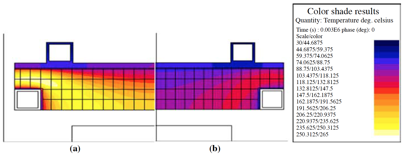
Thermal calculations were done using the same Flux program. The heat sources in copper and flux density in the core have been taken from electromagnetic simulation. There is no standard option in the program to take into account the heat due to magnetic losses in the core. To incorporate the Fluxtrol material in the thermal evaluation, the known relation of flux density and frequency to power losses were imported. Fluxtrol material has the relationship: Pv = cB^(a)f^(b) where Pv is the volume power density, c is a constant, B is flux density, f is frequency, a has a value from 2 to 2.2, b has a value from 1 to 1.25 depending on material and frequency. The results from Flux 2D are shown in Figure 6, displaying one-half of the inductor cross-section. Figure 6(a) has a core made of Fluxtrol 50. The cooling plate is also included on top of the concentrator, with a thin layer of thermally conductive epoxy in between. The concentrator cross-section was broken into multiple squares of constant B values to approximate the power losses throughout the concentrator. The results show a maximum temperature of 2628 C. This is too high for safe operating conditions, both for the sake of overheating the samples and for the concentrator sustainability. Generally, Fluxtrol material will begin to degrade in air above 2508 C.
The first step taken to reduce the amount of power losses was favorably orienting the concentrator material. Fluxtrol has anisotropic properties with minimal losses and highest thermal conductivity in a plane perpendicular to direction of pressing (www.fluxtrol.com). Simulation was done to see the differences with orientation, using multiple pieces of concentrator oriented in favorable direction. The results showed a 688 decrease in maximum temperature.
Although simulation has shown a significant decrease in temperature after orienting the concentrator, the inductor temperatures need to be suppressed much more, especially at the heat face surfaces. The next step taken for further thermal mitigation of the concentrator was an investigation on other possible material grades that may have more desirable properties for this application. After some research and comparison, it was concluded that Fluxtrol 75 would be the more suitable candidate, with roughly the same power losses but double the thermal conductivity as Fluxtrol 50 in the favorable direction. The results using oriented Fluxtrol 75 are shown in Figure 6(b). The maximum temperature resulting from this material was reduced by an additional 508.
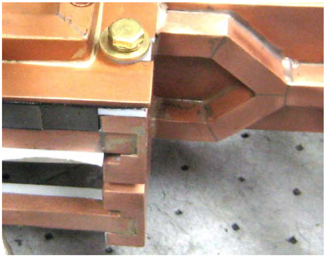
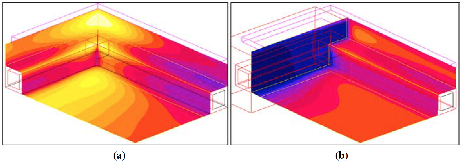
The 2D results shown so far are with the view of looking into the page as the longest dimension. Owing to three-dimensional magnetic fields near each end where the winding crosses over, the concentrator loading will be greater than seen in the 2D results. The highest temperature region shown so far has been at the outer edges between the winding and cooling plate. At the corners of the inductor, where a 908 junction exists, the hot region will become much hotter with the greatest influence of 3D fields being at each corner (Figure 7). To help predict the temperatures at the corners of the inductor, Flux 3D program had to be used. The temperatures in the concentrator from the 3D simulation are shown in Figure 8 for oriented Fluxtrol 75. One-eighth of the total inductor was modeled due to symmetry. The top corner of the concentrator in Figure 8(a) can be seen as the highest temperature region, as expected. The maximum temperature at the corner is 2038, which is an increase of almost 608 from the maximum temperature of 2D results. In order to reduce overheating of the corners, the 3D magnetic field had to be reduced. To do this, the concentrator was partially removed from above the cross-over leg and the winding was widened in this section to about triple the height and double the thickness (Figure 7). Additional copper masses reduce 3D effects and the concentrator heating in this area. Magnetic field becomes closer to 2D with the temperature distribution similar to that of Figure 6. The effect of copper widening is clearly demonstrated by the thermal models of Figure 8. The maximum temperature then returns to about the same value as seen in Figure 6, and in the same region. The resulting electrical parameters are very close to those from 2D (Table I).
After simulation was used to predict any possible concerns with overheating and thermal management techniques were implemented, the coil design was finalized and built. Once built, the coil was tested to validate results from simulation.
The available equipment limited testing to a maximum of 500 V in the power supply, which led to an inductor voltage of 480 V. At this voltage, the mean field strength along the center was 22.6 kA/m at 155 kHz. Proportionally for 31.8 kA/m at 150 kHz (the conditions the coil must operate in), this means that 654 V will be needed in the coil head. This is close to the 650 V predicted by simulation. Thermal measurements were taken of the coil as well. The hottest surfaces of the inductor were in the same areas as simulation predicted. Testing at the lower voltage conditions, the maximum temperature was just below 1008 C. Proportionally, this correlates to about 40 8 higher than simulation for a field strength of 31.8 kA/m, but is still within the threshold of the concentrator. This means the water cooling conditions used in simulation were over-estimated. New results were created with reduced water cooling in order to calibrate to the experimental results observed. If any further changes need to be predicted, this will provide more accuracy.
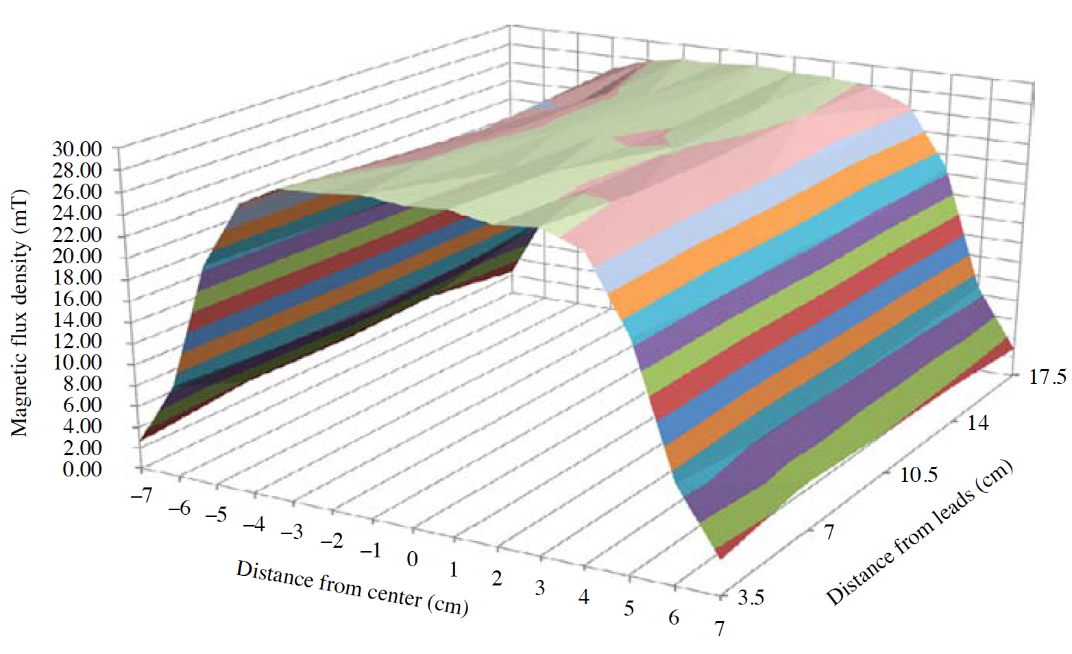
The magnetic field distribution had to be verified and compared to predictions. The goal was to produce a uniform field throughout the area contained by the specimens (7.5 cm £ 11.5 cm), which should be able to reach 31.8 kA/m with higher voltages. Using a maximum power supply voltage of 500 V, a magnetic field probe was used to collect readings of field strength at the central height between the turns. Readings were taken at five different locations equally spaced from the inductor leads using an inductive probe manufactured and calibrated at AMF Life Systems. At each location, 15 points of data were collected from edge to edge, to map the distribution of field between the windings. The results are displayed in the plot of Figure 9 with magnetic flux density in mT presented. The plot shows a flux density of 27.5^1 mT throughout the entire area to be contained by the specimens. This is equivalent to 21.9 kA/m^3.5 percent, which is in the limits of the desired amount of uniformity.
The maximum temperatures of the inductor predicted by simulation and observed in experiments were both higher than the allowed 398 C. To prevent interference of the higher temperatures of the inductor with the specimens, a method to thermally isolate the inductor from the specimens was developed. This method entailed a plastic cooling plate applied to both internal faces of the inductor. The cooling from these plates was not high enough to sufficiently reduce the coil temperatures, but provided enough cooling to serve its purpose of shielding the samples from external heat. Additional cooling methods have been proposed to further reduce the temperatures of the coil if required. Internal cooling of the concentrator is a possibility. This can be done by cutting cooling channels in a plate of the material and sealing another plate on top using epoxy compound. This technique has been proven out already by AMF Life Systems.
Tests showed that selection and application of adhesives for the construction of the coil was critical. The thermal properties of adhesives between the copper and concentrator have a strong impact on concentrator temperature. A two-part thermally conductive epoxy was used in the construction of this inductor. A smooth uniform layer of the adhesive assured no air pockets in the glue.
Conclusions
Hyperthermia treatments using magnetic nanoparticles have shown the potential to provide a low side effect therapy for cancer treatment in vitro and in vivo. So far, this therapy has limited clinical results. In order to understand better the underlying principles and requirements, AMF Life Systems and Johns Hopkins University have partnered together on research in this area. To increase the amount of tests, multi-well culture dishes are utilized. Owing to the size of this dish and relatively high fields (32 kA/m) and frequency (150 kHz), traditional Helmholtz coils require very high voltage, current, active and reactive powers. Owing to this, alternative coil designs were studied.
The most prospective design was a rectangular coil with magnetic core made of Fluxtrol material. Simulation results predicted that the rectangular coil with magnetic core produces required field levels and uniformity with approximately six times lower reactive power than a Helmholtz coil. After the type of coil was chosen, there was still a persistent concern with controlling the coil temperatures to a reasonable level. It was found that the concentrator material and orientation had a large effect on its heating. The optimal grade of concentrator for the best combination of thermal conductivity and power losses proved to be Fluxtrol 75. Main overheating of the concentrator takes place at the corners of the inductor due 3D magnetic field in these areas. This effect was significantly reduced by widening the copper tube geometry of the cross-over legs.
Experimental data confirmed the results of simulation. The magnetic field was well within the desired range of uniformity. The maximum surface temperature of the coil, calculated from experiments, was about 408 C higher than simulation value for the desired field strength. This temperature is still within the limits of the material threshold. To isolate the specimens from the high temperatures of the coil, cooling plates were applied to the coil.
References
[1] Adair, E.R. and Black, D.R. (2003), Bioelectromagnetics Supplement, Vol. 6, pp. S17-S38.
[2] DeNardo, S.J., DeNardo, G.L., Miers, L.A., Natarajan, A., Foreman, A.R., Gruettner, C., Adamson, G.N. and Ivkov, R. (2005), Clin. Cancer Res, Vol. 11, pp. 7087s-92s.
[3] DeNardo, S.J., DeNardo, G.L., Natarajan, A., Miers, L.A., Foreman, A.R., Gruettner, C., Adamson, G.N. and Ivkov, R. (2007), J. Nucl. Med., Vol. 48, pp. 437-44.
[4] Dughiero, F. and Candeo, A. (2008), paper presented at 13th Biennial IEEE Conference on Electromagnetic Field Computation, Athens.
[5] Gruettner, C., Mueller, K., Teller, J., Westphal, F., Foreman, A.R. and Ivkov, R. (2007), J. Magn. and Magn. Mater., Vol. 311, pp. 181-6.
[6] Ivkov, R., DeNardo, S.J., Daum, W., Foreman, A.R., Goldstein, R.C., Nemkov, V.S. and DeNardo, G.L. (2005), Clin. Cancer Res, Vol. 11, pp. 7093s-103s.
[7] Johannsen, M., Gneveckow, U., Taymoorian, K., Thiesen, B., Waldöfner, N., Scholz, R., Jung, K., Jordan, A., Wust, P. and Loening, S.A. (2007), International Journal of Hyperthermia, Vol. 23, pp. 315-23.
[8] Lehmann, J., Natarajan, A., DeNardo, G.L., Ivkov, R., Foreman, A.R., Catapano, C., Mirick, G., Gruettner, C. and DeNardo, S.J. (2008), Cancer Biotherapy and Radiopharmaceuticals, Vol. 23, pp. 265-71.
[9] Natarajan, A., Gruettner, C., Ivkov, R., DeNardo, G.L., Mirick, G., Yuan, A., Foreman, A.R. and DeNardo, S.J. (2008), Bioconjugate Chemistry, Vol. 19, pp. 1211-18.
[10] Nemkov, V. and Goldstein, R. (2007), Proceedings of International Symposium on Heating by Electromagnetic Sources, Padua, Italy, pp. 191-9.
[11] Overgaard, J. (1985) in Overgaard, J. (Ed.), Hyperthermia Oncology, Taylor & Francis, London.
[12] Streffer, C. and Van Beuningen, D. (1987), Hyperthermia and the Therapy of Malignant Tumors, Springer, Berlin.
If you have more questions, require service or just need general information, we are here to help.
Our knowledgeable Customer Service team is available during business hours to answer your questions in regard to Fluxtrol product, pricing, ordering and other information. If you have technical questions about induction heating, material properties, our engineering and educational services, please contact our experts by phone, e-mail or mail.
Fluxtrol Inc.
1388 Atlantic Boulevard,
Auburn Hills, MI 48326
Telephone: +1-800-224-5522
Outside USA: 1-248-393-2000
FAX: +1-248-393-0277
Related Topics
- Design of Induction Coil For Generating Magnetic Field For Cancer Hyperthermia Research
- Modified Solenoid Coil That Efficiently Produces High Amplitude AC Magnetic Fields with Enhanced Uniformity for Biomedical Applications
- Application of High Amplitude Alternating Magnetic Fields for Induction of Nanoparticles Localized in Cancer