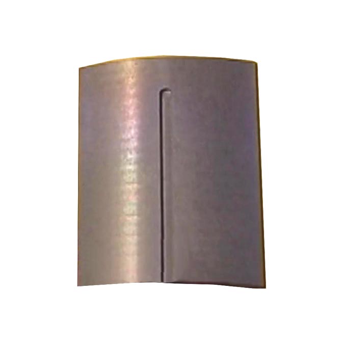
Magnetic Controller Protection
In many applications Fluxtrol controllers work in special conditions. Factors that can thwart use of controllers and the coil copper or cause their premature failure:
- Mechanical damage by the part or during the coil installation.
- Material overheating resulting in crumbling. Overheating may be caused by insufficient cooling of the coil, improper design and manufacturing or by concentrator separation from the coil tubing due to cracks in glue.
- Environmental impact. In vacuum furnaces special attention must be paid to controller cooling because of absence of convection. Aggressive atmospheres can cause chemical degradation of the controller.
- Electrical discharge from one living part to another or to ground can cause arcing and material “burning”.
- Many means and methods may be used for protection.
Mechanical Protection
Mechanical damage is one of the main factors in coil / concentrator failure and proper preventive measures must be taken:
- Use coil design that prevents mechanical damage
- Check correct position of the concentrator relative to the coil, fixture and moving parts of machine
- Check conditions of carbide shoes or other components that provide required gap.
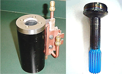
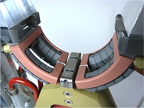
The coil turns were potted in epoxy and stainless steel guide installed on the coil entrance.
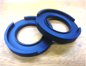
Fluxtrol ring was installed between the coil and the guide to prevent its heating.
Ceramic Coating
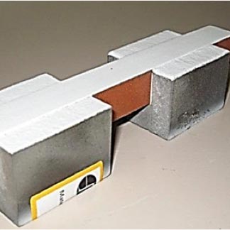
Ceramic coating (Al2O3, ZrO2, etc.) can effectively protect the coil face from mechanical and thermal damage in case of occasional touch of the hot parts. Coating can be applied to the whole assembly “coil-concentrator” or separately to the Fluxtrol part. Hot ceramic particles penetrate into the Fluxtrol material forming strong surface layer. Do not use metallic substrate layer before applying ceramics in order to avoid additional induced losses.
Plastic Coating
Different plastic coatings and application technologies may be used to protect Fluxtrol controllers or the whole coil assembly from harsh environments and meet special service requirements.
Thin Teflon coating is an excellent protection of magnetic controllers for food industry (FDA approved), clean rooms, medical applications, etc. Coating thickness can vary from several microns to more than 20 microns depending on coating type and technology.
Impregnation
Impregnation is saturation of surface layer of metallic and composite materials by special epoxy. It is commonly used to seal pores in powder pressed or cast parts, e.g. aluminum cast blocks of engine.
- Clean surface with sealed pores
- Better mechanical strength
- Reduced surface and volumetric corrosion
- Prevention of water and aggressive fluids penetration inside the material
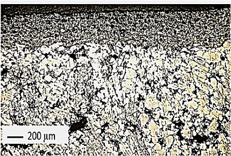
- Depth of penetration depends upon the material type; e.g. for Fluxtrol 50 it is app. 0.25” (6.3 mm)
- Impregnation does not change magnetic properties and thermal conductivity of material
- Recommended sealant is Loctite PMS-50E from Henkel
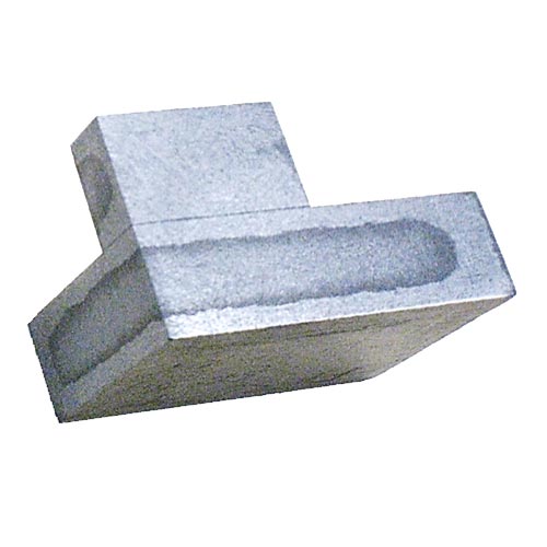
A cut of two impregnated samples of Fluxtrol 50 glued together with epoxy 50-3100 Lighter surface areas – impregnated layer
Etching
Main Goal: To remove or modify conductive surface layer created during machining operations for better electrical resistance and electrical strength to applied voltage.
Additional Benefits:
- To reduce rusting
- To remove loose particles and prepare surface to gluing or coating
Etching materials:
- Don’t use chloric, nitric or sulfuric acids; they can damage material Phosphoric acid may be used for etching and rust prevention
- Fluxtrol Inc. recommends special iron-phosphoric agent CrysCoat 187, produced by Chemetall Oakite, or similar agents used for surface cleaning before painting and coating.
- These agents etch iron surface destructing the smeared layer and form a layer of phosphates that prevents corrosion
Recommended Etching Procedure
- Parts must be clean; clean oily spots, paint and other grease using organic solvent such as acetone
- Use stainless steel, ceramic or acid and temperature resistant plastic container
- For best results use 20% concentration of Cryscoat solution, i.e. 1 part of standard etching agent to 4 parts of clean water by volume
- Place Fluxtrol parts into preheated solution (temperature – 160 F = 75 C) for 15 min
- Maintain temperature in bath at required level; a crock pot may be effectively used for small batches of material
- Use spacers between material pieces and between pieces and bath bottom for secure contact of all the surface to solution
- Remove parts from the solution and thoroughly rinse in clean water
- Dry parts with paper towel or compressed air
- Keep parts in dry room temperature area for at least 24 hours for better results (resistance continues to grow during this period after etching).
Concentration control and spent liquid disposal
- Due to reaction the chemical composition of solution changes after etching of several material batches
- The best method of etching solution control is measuring its acidity using Ph meter such as PH 220 EXTECH Instruments
- Ph factor of fresh solution must be in a range 2.8-3.5. When Ph factor goes above 3.5, which corresponds to less acidic reaction, add more etching agent to return Ph to required level
- In the process of etching the solution color changes from light yellow to dark yellow-brown and a layer of slug appears on the container bottom. Periodically clean the container
- For spent liquid disposal use standard procedure for acidic solutions accepted at your plant that should meet the local environmental requirements; contact manufacturer for specific instructions.
- Contact Fluxtrol Inc. at +1 248 393 2000 or Fluxtrol@fluxtrol.com for additional information, questions or suggestions.
