Information
Authors: R. Goldstein, V. Nemkov and R. Madeira
Magazine: Industrial Heating, December 2006
Vehicle axles are a component that has been induction heat treated for many years. Demands for increased vehicle reliability, fuel economy and performance have led to more challenging heat-treatment specifications for this automotive component.
While being asked to produce better product, automotive parts suppliers have been faced with increased competition and relentless demands to lower costs. A fundamental study using computer simulation revealed that there was significant potential for cost savings on induction-scaning coils by incorporating precision-machined inductors with selective use of magnetic flux controllers. The cost savings come in the form of improved part quality, reduced sensitivity, increased repeatability, increased production rates and energy savings. These results have been validated in several production facilities on both semi-float and full-float axles. A case story will be presented to demonstrate typical results.
Introduction
In the early 1930s, the first industrial induction heat-treating processes were developed. Vehicle axles were some of the first parts induction hardened. There are two main processes for induction heat treating of axles – scanning and single shot. This paper focuses on induction-scanning processes. Induction axle-scanning installations typically utilize single or two-turn profiled inductors made from formed tubing. Two-turn profiled inductors are used wherever possible because they offer energy savings and higher possible production rates. The drawbacks of two-turn inductors are the ability to properly treat the fillet area and run-out at the end of the shaft. Single-turn profiled inductors are used when it is not possible to meet the heat-treatment specifications using a two-turn inductor.
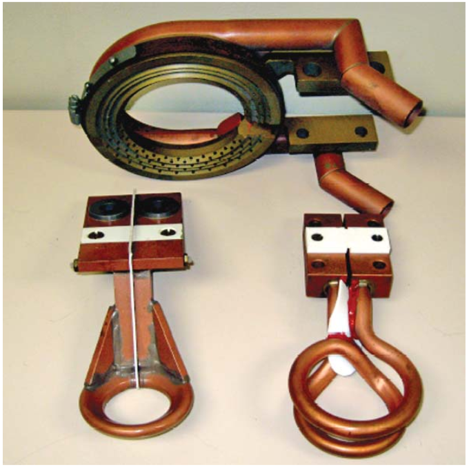
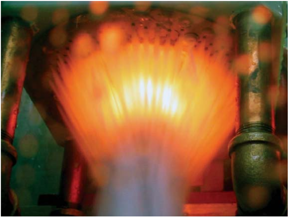
A picture of typical single and two-turn scanning inductors along with a brass quench ring is shown in Fig. 1. The brass quench ring is mechanically fastened to, but electrically isolated from the coil interconnect with the buss bars. In some cases, a nonmetallic quench ring is used instead of brass. A picture during the axle-scan hardening process is shown in Fig. 2.
These traditional inductor designs were developed empirically during the rapid-technology-adoption time for induction heat treating (1930 –1970), and they offered significant cost savings compared to other competitive heat-treating technologies. Through process settings and coil diameter adjustment, it was possible to treat a wide variety of axles using the same equipment.
To succeed in today’s more competitive marketplace, however, it is not only necessary to compete against other processes but also against other plants with induction-hardening capabilities. Sometimes these other plants are from the same company. Therefore, the demand for cost minimization is increased, and a new level of productivity is required in order to stay competitive.
Intensive study using computer simulation revealed that for all axles studied so far, there was the potential to provide greater than 15% energy savings, or a 15% increased scanning speed using the same equipment and new optimized induction coils. These savings are achieved – while at the same time improving upon the heat-pattern profile – by reducing sensitivity to part positioning, decreasing distortion and improving the fatigue strength.
Optimized axle-scan hardening inductors designed using computer simulation have been successfully implemented at several production facilities. These inductors have demonstrated savings consistent with predictions. A case story using a generic full-float axle is used to demonstrate the optimization procedure and production benefits.
Case Story – Full-Float Axle with Bowl
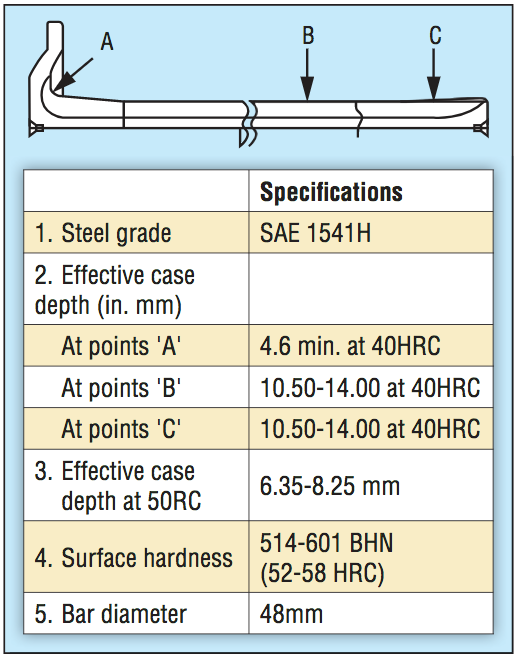
Heat-treatment specifications for a common 48 mm-diameter truck axle are shown in Fig. 3. Surface hardness should be 52-58 HRC, and the minimum case depth is 10.5 mm for 40 HRC (Point B) in the shaft and greater than 4.6 mm at a 45-degree angle from the center of the fillet (Point A). There must be some hardened area on the entire surface of the fillet radius, and the pattern must end before the exit of the bowl.
Truck axles with around 1-cm case depth are typically hardened using 400 or 600 kW dual-spindle scanners at 1 or 3 kHz. In production, this axle was being produced using a 400-kW, 1-kHz power supply. The heat treater also had 400-kW, 3-kHz scanners available, so both 1 and 3 kHz were studied. The main design tool used for comparison was Flux 2D electromagnetic plus thermal computer-simulation program.
Simulation Analysis Parameters
When performing computer simulation and calculating power values, it is important to note that for a dual-spindle scanner the losses in the heat station and busswork are oftentimes comparable to the power in the coil head and busswork. These losses are proportional to the square of the coil current at a given frequency. Also, it is often difficult to get over 80-90% of the rated power from this type of power supply due to matching limitations. With this in mind, we’ll set the maximum power in a coil head to 100 kW (200 kW for 2 spindles, does not include losses in the busswork and transformer).
Another limit for the process is the maximum temperature of the axle to prevent grain growth, poor microstructure and possible crack formation. For this reason, we’ll set the limit on surface temperature during the scan to 1100°C (2012°F), with an allowance for up to 1120°C (2048°F) in the area just above the fillet.
The final limit – the minimum coupling gap from the bottom of the inductor – is set to 1 mm. This is based on an assumed normal operating gap of 1.5+/-0.5 mm, typical for this type of installation. The radial coupling gap is set to 8 mm for all cases due to the 10-mm radius of the fillet.
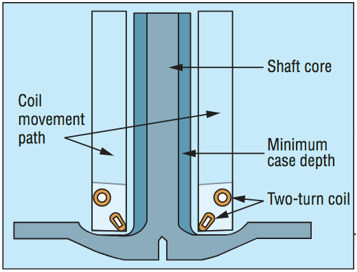
The geometry used for computer simulation of a standard two-turn scan coil is shown in Fig. 4. The minimum case depth is marked off in the drawing as a point of reference. The box around the inductor is drawn to facilitate coil movement in the process of calculation.
Analysis Results
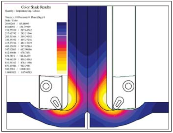
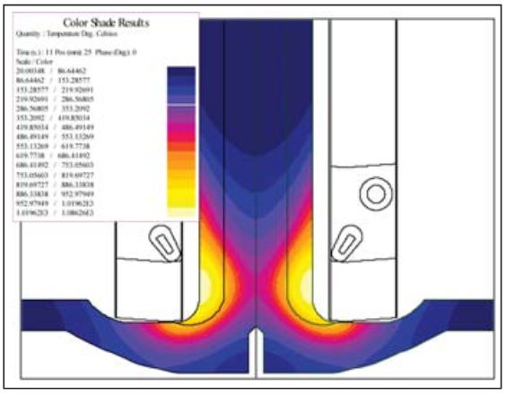
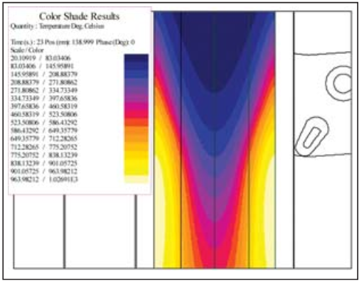
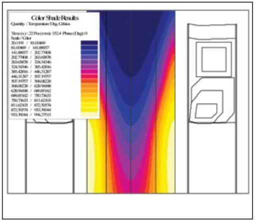
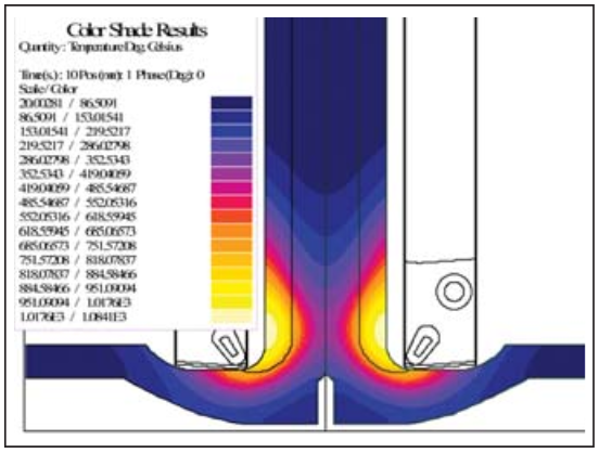
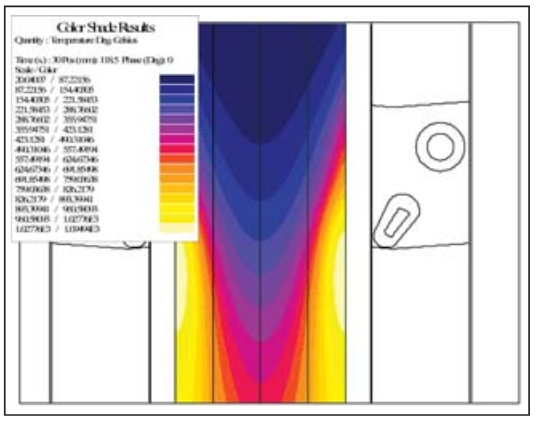
Figure 5 shows the temperature distribution for a standard two-turn coil after a 10-second dwell with a 1-mm gap from the bottom of the inductor. The time and power combination were determined by achieving the proper basis for a good heat pattern in the fillet. The pattern extends through the fillet without significant overheating above the fillet (maximum temperature 1075°C, or 1967°F). Figure 6 shows the temperature distribution one second later after a 20 mm/second fast scan out of the fillet area with lower power to avoid overheating of the area just above the fillet that was preheated from the dwell (temperature 1090°C). Finally, Fig. 7 shows the temperature distribution during the scanning process. The scanning speed is 9.5 mm/second and was limited by the power of the generator (100 kW in the coil head, only 1025°C surface temperature). To minimize heating time for deep-heating applications (ie. mass heating of billets prior to forging), it has been shown that faster processing speeds are achieved using power profiling 1. Using this method, high power is used during the early stages of the process to rapidly bring the part surface close to the desired temperature. Subsequent stages have progressively lower power levels to hold the surface temperature at a given level while the core temperature rises.
The same principle can be applied to axle-scan hardening with two-turn inductors. The more power we put in the part from the upper turn, the faster we can scan. The problem is how to heat the fillet without overheating the area just above it. The more we move the top turn in, the more the maximum temperature will shift up the shaft and away from the fillet. To resolve this issue, it is necessary to both add power at the top of the coil to increase potential scan speed while at the same time adding power to the fillet and flange area. This can be accomplished by using Fluxtrol A magnetic flux controller on the lower loop and changing the winding geometries.
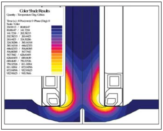
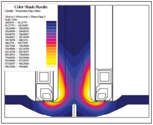
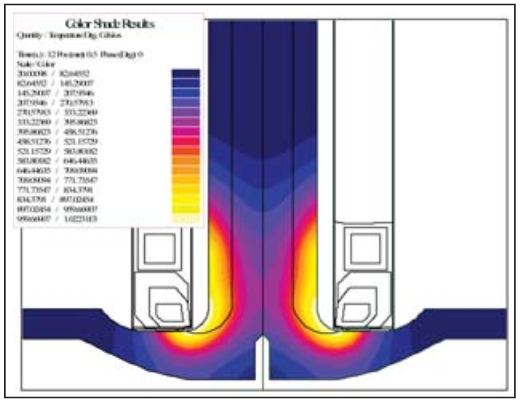
Figure 8 shows the temperature distribution for an optimized two-turn coil after an eight-second dwell with a 1-mm gap from the bottom of the inductor. The time is shorter because it is much easier to heat the fillet area with this design. The pattern extends through the fillet without significant overheating above it (maximum temperature 1000°C, 1832°F). Also, the heating is spread more uniformly along the surface and farther up the shaft, setting the tone for faster scanning and eliminating the need for a rapid exit from the dwell. Figure 9 shows the temperature distribution during the scanning process. The scanning speed is 11 mm/second (compared to 9.5 mm/second for the traditional inductor), and it was again limited by the power of the generator (100 kW in the coil head, only 1000°C surface temperature).
Process Optimization
The pattern developed using the 1-mm gap for both inductors looks reasonable, but this is at the bottom end of our tolerance. To evaluate the sensitivity to positioning, simulation was made for both cases with the coupling gap increased to 2 mm (upper end of the tolerance). For both cases, the same dwell time and power level are used because in production that’s how the machine will operate. The heat pattern in the dwell for the standard two-turn inductor is shown in Fig. 10, and Fig. 11 shows the pattern for the new optimized inductor. With the traditional two-turn, the heat pattern now does not extend completely through the fillet, and this part would most likely be out of specifications. With the new optimized inductor, the pattern still goes through the fi llet, and the part is well within specifications.
The main limitation at 1 kHz in both cases is the power of the power supply. For the standard two-turn inductor, there is also the issue with achieving sufficient depth in the fillet and sensitivity to positioning. A very small difference in position could lead to the part falling out of specification. With the optimized two-turn inductor with Fluxtrol A, much more variance in positioning is possible, leading to a more robust process. Besides reduced sensitivity to positioning, the optimized two-turn inductor also can scan just over 15% faster with the same power.
Analysis with 3-kHz Scanner
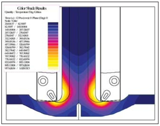
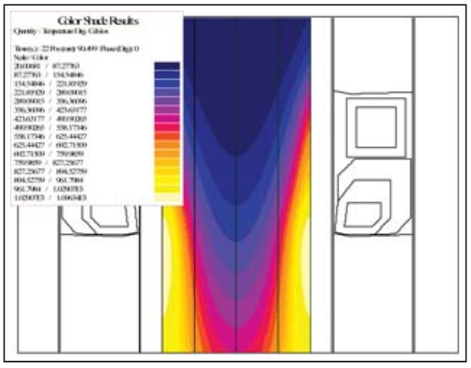
Besides 1 kHz, these axles may be produced on a 3-kHz machine. Figure 12 shows the temperature distribution at the end of the dwell for the same standard two-turn in-ductor with a 1-mm gap. Compared to 1 kHz, the dwell time required was longer (12 vs. 10 seconds), and the heating of the fillet area is much better. At the same time, the contribution to heating from the top turn is less. This is due to the increased proximity effect at higher frequency 2. During the scanning process, the limitation at 3 kHz is not the power, but the surface temperature of the shaft. Figure 13 shows the temperature distribution during the scanning process at 3 kHz. The scan speed had to be reduced to 6.5 mm/second to avoid overheating the surface (temperature 1100°C).
For the optimized inductor, the situation is similar, but a 2-mm gap was used instead of 1 mm because there was more than adequate heating of the fillet at the larger gap. The inductor geometry itself was identical to the one used at 1 kHz. The dwell time had to be increased to 12 seconds to ensure sufficient depth throughout the fillet area (Fig. 14). During the scanning process, the differential between additional heating from the top turn is even greater than at 1 kHz. It was, therefore, possible to scan at 9 mm/second (Fig. 15).
At 3 kHz, the limitation is set by the maximum surface temperature. Heating of the fillet area is much easier in both cases due to increased proximity effect. So much so that in the case of the optimized two-turn inductor it was possible to increase the gap consideration to 2.5+/-0.5 mm, leading to a bigger safety factor in production. Because the limitation has moved to surface temperature, the benefits of the optimized coil design are much more pronounced. The scan speed advantage at 3 kHz is over 35% for the optimal design compared to 15% at 1 kHz.
Conclusions
Vehicle axles are a component that has been induction heat treated since the 1930s. The automotive powertrain industry has become much more competitive over the past decade, and there is significant pressure on parts suppliers to continually work to lower costs. There are two main processes for induction heat treating of axles – scanning and single shot. A study using computer simulation revealed that there was significant potential for cost savings on induction-scanning coils by incorporating precision-machined inductors with selective use of magnetic flux controllers.
A generic full-float axle was used to show the benefits of an optimized induction coil with Fluxtrol A compared to the standard two-turn inductor commonly used in practice. The study showed it was possible to significantly increase the scan speed (15% at 1 kHz, 35% at 3 kHz) using the optimized induction-coil design. The study also showed the influence of frequency on the processing parameters for induction-scanning applications.
There is not one optimal coil design for all axles. The optimal induction-coil design depends upon the induction machine, the axle geometry and the heat-treatment specifications. Computer simulation is the best tool to determine the optimal induction-coil design and operating conditions for a given axle.
Several axle-scan hardening induction coils optimized using computer simulation are currently being used in production. All have demonstrated increased productivity in the form of increased scan speed and/or energy savings.
References
[1] S Lupi, A Mulbauer, D Bose et al. Induction Heating Industrial Applications. UIE, France, 1992.
[2] Ruffini, R.S., Ruffini, R.T., Nemkov, V.S., Goldstein, R.C. Power Inductor Technology for Induction Heat Treating of Automotive Parts. Global Powertrain Conference. 1999. Stuggart, Germany.
If you have more questions, require service or just need general information, we are here to help.
Our knowledgeable Customer Service team is available during business hours to answer your questions in regard to Fluxtrol product, pricing, ordering and other information. If you have technical questions about induction heating, material properties, our engineering and educational services, please contact our experts by phone, e-mail or mail.
Fluxtrol Inc.
1388 Atlantic Boulevard,
Auburn Hills, MI 48326
Telephone: +1-800-224-5522
Outside USA: 1-248-393-2000
FAX: +1-248-393-0277