Information
Authors: C. Myers, J. Osborn, C. Tiell, R. Goldstein and R. Ruffini
Magazine: Industrial Heating, December 2006
The first industrially induction hardened part was a crankshaft (the early 1930s). As time went on, crankshaft designs became more complicated and heat-treatment specifications became more challenging. At the same time, crankshaft coil design has not advanced significantly since the 1960s. In many cases, this has resulted in limited ability to meet newer part specifications and short induction-coil lifetimes.
Norton Manufacturing (Norton), a manufacturer of automotive, medium and heavy-duty trucks, off-highway and aerospace crankshafts, partnered with a specialist in induction-coil optimization and a manufacturer of magnetic flux controllers, to address their induction heating coils. The first phases of this project have led to significant improvements in the induction heating coil performance. The following details the preliminary findings from this collaboration and provides an outline for future developments.
Introduction
In the early 1930s, the first industrial induction heat-treating processes were developed. Nearly simultaneously, TOCCO (USA) and Russia developed commercial processes for induction hardening of crankshaft pins and journals [1, 2, 3]. This very successful development helped to spur a new age of induction heating and a great number of new heating and heat-treating applications emerged throughout the world.
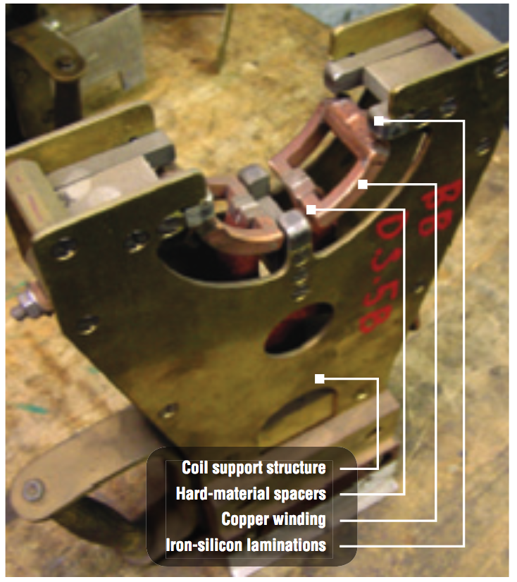
Initially, clamshell inductors were used with mechanical, hydraulic or pneumatic locking mechanisms. As automotive volumes increased, this style of induction installation had limited ability to keep up with production. To solve this problem, Elotherm developed a non-encircling inductor that would rotate with the part in 1941. Further design improvements occurred around 1950 with a U-shaped induction heating coil [3]. In this process, the crankshaft rotates in centers. U-shaped induction heating coils with magnetic flux concentrators are applied to the journals, which must be hardened (Fig. 1). Hard material spacers installed on the coil structure provide fixed coupling gaps between the coil and the part surfaces.
Norton Manufacturing Company, located in Fostoria, Ohio, has been in business for over 50 years and has been producing crankshafts since 1978. Norton’s customers include General Motors, DaimlerChrysler, Ford Motor Company, Volvo/Mack, Textron Lycoming and International Truck and Engine. Norton supplies crankshafts for a wide range of vehicles, including the Dodge Viper and the Humvee military vehicle.
In 1995, Norton purchased equipment and began using induction for hardening the crankshaft journals. In 2004, the power supplies were upgraded to new IGBT based units from AjaxTOCCO Magnethermic. Three machines are currently dedicated to induction hardening of crankshafts, utilizing more than 150 different induction heating coils.
Induction coils are developed, built and maintained in-house with a fully equipped induction department. This allows Norton to closely monitor the performance of their coils and track critical values such as number of cycles between failures, number of coil rebuilds possible between manufacturing of new coil, etc. It also allows them to examine the failure modes of all the coils it uses in an effort to improve both coil performance and coil life.
Technical Challenges
Rapid product-development cycles and tighter heat-treatment specifications due to the need for reduced variation to meet six sigma quality requirements are placing increased pressure on vehicle-part suppliers. Despite the experience and knowledge present at Norton, these market forces have created a demand for even better understanding of the induction-heating process. Continuously changing tighter product requirements mean what was good just a few years ago is no longer good enough. At the same time, the marketplace price pressures mean the component manufacturers must improve the processing capability of their equipment relentlessly without increasing cost [4].
Norton’s analysis of their operations showed that the biggest benefits could be achieved by improving the overall quality of the induction heating coil. The induction heating coil quality was defined by the following parameters:
- Heat pattern
- Development time
- Coil lifetime
- Repeatability
- Repair time
- Tooling changeover time
The relative importance of these variables depended upon the specific features of a given crankshaft.
To work on increasing the overall tooling quality, Norton collaborated with Fluxtrol, a company specializing in induction-coil optimization and magnetic flux controllers.
Coil Improvement
A collaborative evaluation of the existing induction-coil technology revealed that the iron-silicon laminations used as flux concentrators limited overall coil quality. In manufacturing and developing inductors, stacks of laminations were applied selectively to the induction heating coil to balance heating between different areas of the part to produce the desired heat-treatment pattern. Laminations have several limitations in their use on crankshaft inductors:
- Exhibit severe overheating in the presence of 3-D magnetic fields [3]
- Require copper “keepers” to mechanically hold them in place and to improve heat removal
- Stacking of many thin sheets with special profiles on curved surfaces is very laborious and difficult to reproduce
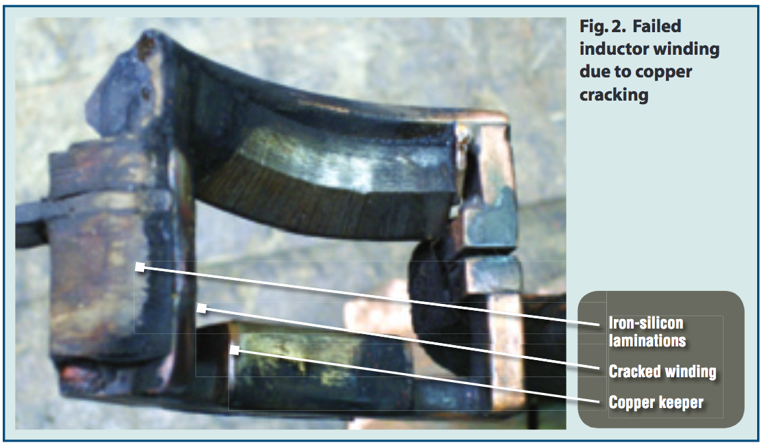
The main failure mode of Norton’s crankshaft inductors was copper cracking under the laminations (Fig. 2). This style of induction heating coil requires very high currents, because the copper-winding surface area is much smaller than part surface area. The high currents lead to excessive power densities in the coil copper, which must be removed by the cooling water flowing through the inductor.
When laminations are used as a concentrator on these inductors, there are significant limitations as to how close the stacks can be installed to the changes in copper winding direction due to 3-D magnetic fields. The copper keepers also reduce the “effective” length and surface area of the inductor, increasing the current demand, because the same power needs to be induced in a shorter length.
Higher currents lead to even higher power densities in the areas of the winding under the laminations, causing significant temperature rise in the copper. When power is turned off, the heat is removed very quickly and the copper returns to the water-cooling temperature. This cycling of temperature causes stresses to develop in the copper that lead to crack initiation and eventual failure [5]. Small reductions in copper temperature can lead to significant increases in induction heating coil lifetime.
There are two ways to reduce the copper temperature: improve the cooling circuit and reduce the local power density. Norton is currently running separate tests to isolate the variables on both methods and has positive results for both. For improving the cooling, new copper tubing with better heat-removal properties is being tested.
To reduce the power density, Fluxtrol A has been used as a replacement for laminations. Fluxtrol A is a soft magnetic composite (SMC). This material can be used effectively in 3-D magnetic fields and does not require copper keepers [3]. This allowed for the use of a longer length of concentrator on the same winding and a subsequent reduction in the coil current required to produce the same total power. The reduced coil current has two beneficial effects:
- Reduced power density in the winding, which leads to lower copper temperature
- Reduced losses in the busswork and power supplying circuitry
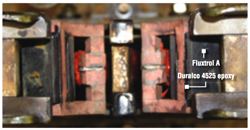
Several tests have been made with Fluxtrol A to date. In all cases, there has been an improvement in the overall induction-coil quality. No changes were made to the inductor copper other than elimination of the copper keepers. The SMC material was machined to the same cross-sectional dimensions as the laminations that were on the standard production coils. The material was glued to the copper winding using Duralco 4525 epoxy as shown in Figure 3. Two examples of induction-coil quality improvement are discussed below.
Results
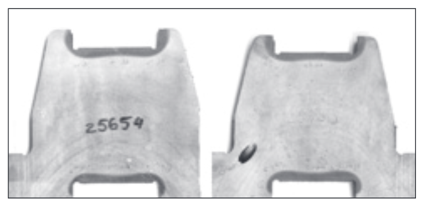
In the first application, the material was applied to a full fillet-hardened crankshaft inductor. It was machined to the same cross-sectional dimensions as the laminations, but the length of the concentrator was slightly longer. A sample part was made using the same power and time settings as for the induction heating coil with laminations. Coil current was lower for the same total power. Metallurgical tests showed that the pattern was more uniform and hardening depth increased in the critical fillet area (Fig. 4).
Further testing showed that the induction heating coil using the SMC material was producing parts that met all of Norton’s quality specifications. The induction heating coil was approved and released for production. The newly designed induction heating coil had a 100% increase in coil lifetime, while the hardness depth was better. The eventual failure mode of the modified induction heating coil was copper cracking. Further coil lifetime improvements are being considered by reducing the power until equivalent hardening depth to their previous inductor is achieved.
Fluxtrol A can be machined to exact dimensions. In another application, it was applied to a non-fillet-hardened crankshaft application. In this application, it had been difficult to achieve the tight specifications set forth by the final customer. Any small difference due to lamination stacking in the induction heating coil manufacturing could lead to the induction heating coil not being able to meet the pattern requirements.
In addition, SMC material was also less restricted on where it could be used on the inductor due to its ability to work in 3-D fields. During the initial process setup, if winding dimensions were not quite exact, the SMC material could be modified with relative ease right on the coil to fine-tune the heat pattern. Using these additional possibilities, they were able to produce parts closer to the middle of the specifications and reduce the initial process set-up time.
Conclusions
Despite Norton's knowledge and history with crankshaft induction hardening, two of the main problems with crankshaft hardening are limited induction heating coil lifetime and the ability to achieve certain heat-treating patterns. Norton Manufacturing and Fluxtrol Inc. are working together to improve Norton’s overall induction-coil quality. The first phases of this project have led to significant improvements in the induction-coil performance.
References
[1] VP Vologdin, Surface Hardening by Induction Method, Leningrad-Moscow, Russia: Gosmetallurgizdat, 1939, 244 p., (in Russian).
[2] FW Curtis, High Frequency Induction Heating, McGraw-Hill, New York, 1944, 235 p.
[3] VS Nemkov, RC Goldstein, “Design Principles for Induction Heating and Hardening,” in the Handbook of Metallurgical Process Design, Marcel Dekker, New York, 2001, pp. 591-641.
[4] VS Nemkov, RT Ruffini, RC Goldstein, CN Grant, SG Wakade, “Induction Heating in the Powertrain Industry,” Proceedings of the 3rd Annual Global Powertrain Congress, Detroit, October 2000.
[5] WI Stuehr, DC Lynch. “How to Improve Inductor Life,” Heat Treating Progress, January/February 2006: pp.33-38.
If you have more questions, require service or just need general information, we are here to help.
Our knowledgeable Customer Service team is available during business hours to answer your questions in regard to Fluxtrol product, pricing, ordering and other information. If you have technical questions about induction heating, material properties, our engineering and educational services, please contact our experts by phone, e-mail or mail.
Fluxtrol Inc.
1388 Atlantic Boulevard,
Auburn Hills, MI 48326
Telephone: +1-800-224-5522
Outside USA: 1-248-393-2000
FAX: +1-248-393-0277