Toll Free


Information
Authors: Robert C. Goldstein, Valentin Nemkov and John Jackowski
Location/Venue: 25th ASM HTS Indianapolis, IN
Topic: Simulation for Heating/Hardening Prediction
Abstract
The time between a product’s definition and production is constantly shrinking. To meet these requirements, extensive use of virtual prototyping has replaced physical models in the mechanical design process. As a result of this, the induction heat treating process developer will often times not receive a quantity of parts for heat treatment until a few weeks prior to having to deliver samples. This makes it nearly impossible to produce good quality parts on time using a traditional test and trial method. The development focus shifts to “just getting a pattern” rather than developing a robust production process. To meet the modern development requirements, the same methods that have led to significant improvements in the mechanical design process are applied to induction heat treating. Virtual prototyping tools include electromagnetic, thermal and metallurgical finite element analysis along with 3-D CAD software. Virtual prototyping allows for the study of a much larger design space in a shorter period of time at lower cost. Final process validation is preformed on real equipment. A case story of an induction heat treating process of wheel hub hardening developed with virtual prototyping is presented. Savings achieved with the virtual tools are discussed.
Introduction
Using induction in metal heat treatments can prove to be a more economical solution in production compared to traditional furnace methods. The downside of induction heat treating is that the development process is more complicated than for furnace heat treatment. There are many steps involved in the development process of an induction heat treating application. This process can be very time consuming in the case of challenging applications with significant geometrical variation and differential case depths.
Similar to furnace heat treatment, induction heat treating process development has typically been done using a combination of experience and experimental data. For parts that are very similar to something developed prior, the development time can oftentimes be quick. For complicated parts though, the majority of the development time is spent running trials, cutting parts and making coil modifications. This trial and error method is quite costly and modifications are made with only limited information and consume precious development time.
Sometimes, it may be difficult to distinguish in advance, which developments will be simple and which ones will be quite troublesome. Due to this uncertainty, induction heat treating process developers have to factor in significant risk when developing parts, which increases the time and cost. Since induction heat treating is one of the last steps in the part manufacturing, parts may arrive later than planned due to difficulties encountered upstream in the manufacturing process, further compressing the time available for experimental development.
Also, it is quite common for some dimensions or features to change from the first drawings of a heat treated part. Induction heat treatment is more sensitive to part changes that furnace heat treatment is. It is often necessary to modify the induction coil to compensate for these changes, but this is typically not determined until you have the new components to test.
Finally, in these complicated cases, the focus of the development shifts from making a robust, reliable manufacturing process to just making a good part. This can lead to the use of coil design and process parameters that may compromise tooling life in production. The impact of this is very difficult to predict based only on empirical information from a relatively small sample of parts.
However; unlike batch furnace processes, induction heat treating with one piece flow lends itself very well to computer modeling. With modern computer simulation tools, there is an excellent opportunity to incorporate the use of virtual prototyping to assist induction heat treating process development. While it increases the initial number of design hours (which occur without having physical parts, therefore not extending the total development time), it will lead to the following advantages:
- Fewer coil modifications
- Fewer trials required with a given coil
- Narrower development time window
- Reduced time to adapt to part changes
- Ability to predict the process, product reliability, and variability
These combined features act to drastically reduce the risk involved in induction heat treat process development. Also, the results of computer simulation become part of a detailed record of the relationship between product characteristics and system parameters. These records may be referenced in the event a problem occurs during production.
Induction Heat Treat Process Development Using Virtual Prototyping
The stages of development for an induction heat treat process vary depending upon the circumstances. In the most complete case, brand new components for induction heat treating and developing a process using virtual prototyping includes the following steps:
- Preliminary analysis of the specifications and available equipment.
- Preliminary process design using computer simulation
- Process type (static or scanning)
- Power, frequency, heating time
- Quench parameters, etc.
- Number of stations required
- Induction coil and process design using computer simulation
- Critical coil dimensions
- Power and motion profile and desired frequency
- Temperature distribution in the part
- Heat treat pattern and part microstructure
- Induction coil temperatures and cooling requirements
- Coil and/or machine engineering using CAD
- Import directly components from catalogues (coil hardware/machine components)
- Identify potential design flaws and interferences
- Determine proper manufacturing techniques including order of operations
- Coil and machine manufacturing
- Experimental tests
- Final modification if required
- Industrial implementation
In many instances, a machine exists already or the part is very similar to something already done and the process may be reduced
Many of the steps involved are the same as in the case of a traditional empirical development. The main differences are steps 2, 3 and 6. The traditional method utilizes simple hand calculations, tables and part history records to determine the preliminary process design. There is no step 3 in the empirical method and as a result history and data from experimental tests are the only information available for coil modification.
To contrast the two methods, virtual prototyping uses computer simulation to virtually explore the design space and provides more information related to the performance of the induction coil and resulting temperature distributions than can be obtained from evaluating cut parts. For those who use statistical methods, it is possible to run DOE trials on the computer instead of with real parts to analyze sensitivity to material composition, DI values, part dimensions, etc.
Up until recently, temperature distributions were used for estimating case depths in the majority of coils and processes designed by computer simulation. Due to continued improvements in computer hardware, software, and material databases it is now practical to model hardness profiles by coupling a metallurgical tool in the software with the heating and cooling results. This tool can also be used to predict other metallurgical properties such as the fraction of phases and grain size.
In the future, we can expect to see continued expansion of virtual tools to replace physical tests in induction heat treating process development. Other available capabilities with simulation software that are not currently used by the authors include effect of upstream operations on incoming properties (casting, forging, machining, etc.), dimensional movement predictions, stresses and part performance [1].
For instance, it is possible to export the metallurgical results into a mechanical simulation program. There, loads could be applied virtually and the real performance characteristics of the part could be evaluated.
Wheel Hub Induction Hardening Case Story
A single-race steel wheel hub for a light duty truck was being induction heated for selective surface hardening. The process was single shot with rotation. The manufacturer was having problems with short inductor life, excessive scrap, and unacceptable down time due to set-ups. The inductor was failing after only 8,000-13,000 parts. 50,000 parts per coil was the required amount to maintain the profit goal on the machine. The induction coil they were using was developed through the traditional trial and error method. The resulting production coil was a multi-stepped single turn coil (figure 1). Laminations and a piece of Fluxtrol A (shown in figure 1) were installed on select regions of the coil to provide the required pattern.
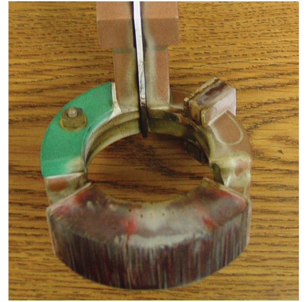
Figure 1: An image of the original production coil with one piece of Fluxtrol A replacing a section of laminations.
An examination of a failed coil showed that copper cracking occurred directly under the laminations due to overheating. Degradation of the laminations also occurred, but was not the reason the coil was taken out of production.
The part producer contacted their vendor and several attempts of corrective action were made. The internal water cooling flow rate was increased, but did not resolve the situation. The laminations in this section of the coil were replaced by Fluxtrol A magnetic concentrator. With the same heat pattern and machine settings, the coil lifetime increased to 15,000 – 25,000 pieces.
This was a significant improvement but still did not meet the 50,000 part goal. After review of the problems, it was determined that for an optimal solution, a new inductor and process design would have to be developed. Time on the machine was at a premium, because the downtime due to inductor failures was already leading to significant overtime just to meet production numbers. Due to limited machine access, the virtual prototyping method was selected for the design of a completely new induction coil.
The main programs used for computer simulation in this application were Flux 2D and Metal 7. Flux 2D is an effective tool for analyzing electromagnetic and thermal fields and may be easily coupled to Metal 7 for analyzing metallurgical properties.
For this case, each coil design modification or process parameter change can be made in less than 1 hour. With computer simulation, it was possible to virtually test over 10 coil modifications in 1 day, allowing us to focus in on the finer details of the design and resolve all potential issues that could arise.
The final design selected was a profiled, single turn induction coil with Fluxtrol 50 concentrator. The temperature distribution predicted by Flux 2D with the optimized inductor is shown in figure 2.

Figure 2: Predicted temperature distribution (°C) in the part
Part quenching after heating was simulated using Flux 2D. A representative mean heat transfer coefficient was selected. Metal 7 was then used to predict the part metallurgical properties. The program allows for the examination of hardness, as well as the fraction of resulting phases with time, as a function of the temperatures simulated in Flux 2D. The predicted hardness pattern in the heated surface of the wheel hub is represented in figure 3. The maximum hardness in the as quenched part (prior to tempering) is about 62 HRC.
Since improving coil lifetime was the main goal of the development, electromagnetic and thermal simulation with complementary hydraulic calculations were done on the coil head to ensure there will be no overheating [2].
Understanding the principles of induction heating, it was known that the profiled nose of the coil would require the greatest amount of cooling followed by the top corner. The engineer responsible for the simulation consulted with an experienced coil CAD designer for best possible cooling method for this inductor.

Figure 3: Computer simulation of the hardness pattern (HRC)
The design engineer suggested a two cooling pocket design to maximize the heat removal from the inductor and minimize resulting temperatures. Cooling in the center of the coil was less critical, so more water pressure could be applied to each corner with this design, as opposed to having one large pocket fill the entire interior.
The resulting maximum temperature predicted by Flux 2D was 94 °C in the bottom nose of the coil (Figure 4). This corresponded well with measurements made during the subsequent tests with a temperature indicating paint (Tempilaq) on the final built coil. Temperatures below 200 C on most induction coil components are considered to be a safe level.
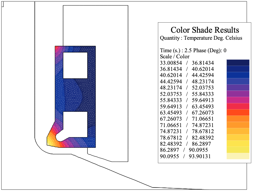
Figure 4: Computer simulation of the temperature distribution (°C) in the coil head using Flux 2D
After the coil design had been proven out by simulation, the coil had to be engineered. The 3D software of AutoCAD was used to create a drawing with all the needed components, as shown in figure 5. This inductor has the top and backside completely surrounded by Fluxtrol 50, which is displayed as green in the figure.
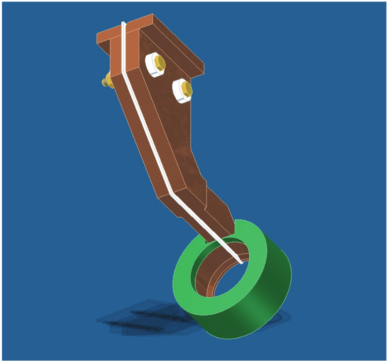
Figure 5: A 3D drawing of the final engineered coil for wheel hub hardening, using AutoCAD
Once the coil was built, it was ready to test with the machine. The predicted material behavior of the program is only as accurate as the data provided to describe the properties. This is one possible source of error when using any simulation program, which is why experimental validation is still required.
After less than half a day of testing parts, a good part was achieved. A sample cut part is shown in figure 6. Comparison of the cut part with simulation (Figure 3) agrees very well with with the predicted results. The sample was sent to the part producer for verification. The hardness profile was confirmed to be within the range of specifications.
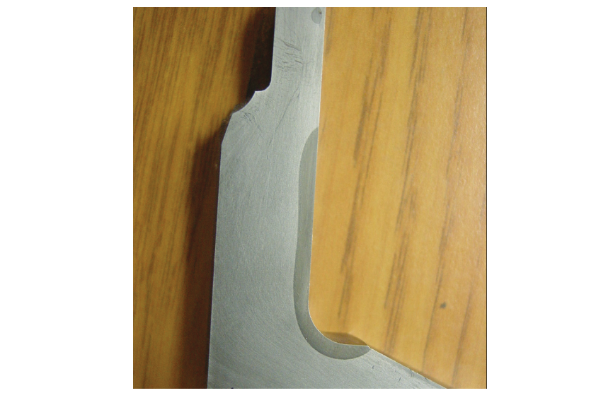
Figure 6: An image of a cut section of the wheel hub, showing the desired hardness pattern
After confirmation that the developed coil was capable of producing good parts, the coil was released into production. With this new design, coil life increased dramatically. The new coil produced over 170,000 parts without coil copper failure, concentrator degradation or pattern change.
The coil was taken out production after 170,000 pieces, because the part was finished with production. A photograph was taken of the coil after its full production lifetime had been performed, which is shown in figure 7 below. The inductor later made another 50,000 pieces for the aftermarket, for a total of over 220,000 parts.

Figure 7: An image of the coil developed through prototyping, after producing over 170,000 parts
Conclusions
In many cases, induction heat treating is a more economical way to produce parts than other methods. The main factor limiting the increased use of induction is time, cost and risk to develop a new process.
Induction heat treating process development has traditionally been done using a trial and error method. A new method, incorporating expanded use of virtual prototyping tools was presented to reduce the risk associated with development process. This method can be used for either brand new parts or solving problems that arise during production.
A case story was presented showing the benefits of this method for induction coil lifetime improvement. The root cause of the failures was determined to be excessive coil temperatures. Computer simulation was used to design a completely new induction coil. The results of computer simulation showed excellent agreement with those achieved on the real machine in terms of both heat treat pattern and induction coil temperature. The lifetime of the new induction coil was more than 10 times that of its predecessor.
References
[1] Cai J., et al, “Integration of Induction Heat Treat Simulation into Manufacturing Cycle,” Heat Treating Progress, Vol. 3, (2003), pp. 36 – 39
[2] Goldstein R., Nemkov V., “Increasing Inductor Lifetime by Predicting Coil Copper Temperatures,” Proc 24th ASM International Heat Treating Society Conference and Exhibition, Detroit, MI, Oct. 2007.
If you have more questions, require service or just need general information, we are here to help.
Our knowledgeable Customer Service team is available during business hours to answer your questions in regard to Fluxtrol product, pricing, ordering and other information. If you have technical questions about induction heating, material properties, our engineering and educational services, please contact our experts by phone, e-mail or mail.
Fluxtrol Inc.
1388 Atlantic Boulevard,
Auburn Hills, MI 48326
Telephone: +1-800-224-5522
Outside USA: 1-248-393-2000
FAX: +1-248-393-0277