Information
Authors: John K. Jackowski, Robert C. Goldstein, Valentin S. Nemkov
Location/Venue: Aeromat 2015
Topic: Carbon Fiber Reinforced Thermoplastics
Overview
- Characteristics of Induction heating Carbon fiber-reinforced thermoplastic (CFRT)
-
Electrical resistivity determination of two specific CFTR’s
- Direction-specific by four-point method
- Equivalent resistivity by impedance method
- Thermal behavior of the studied materials
-
Electromagnetic computer simulation of induction heating a lap joint
- Different coil designs examined
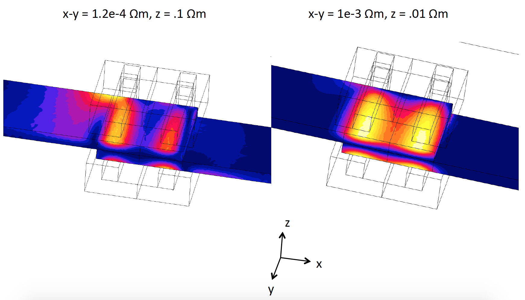
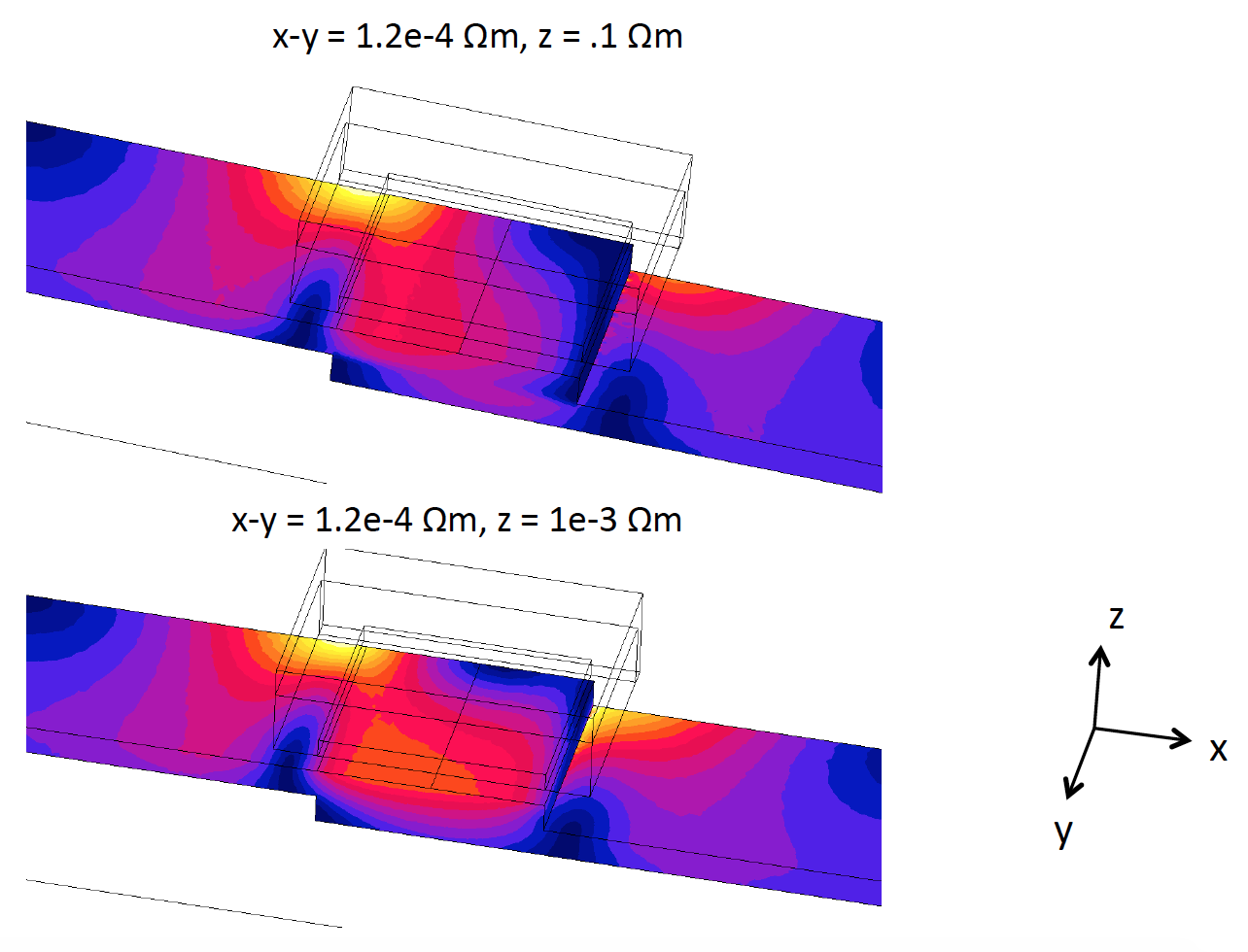
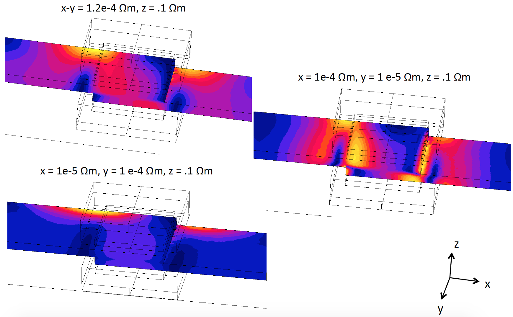
- Current flow with resistivity differences examined
Characteristics of the Induction Method
- Contactless
- Generates heat volumetrically
- Heating can be local or global
- Clean, efficient, small footprint
- Difficult to produce uniform temperatures for complex and large geometries -> highly dependent on coil and process design
- This technology must be well understood to utilize its full benefits
Mechanisms of Heating Thermoplastic Composites by Induction
-
The material to be directly heated must be either electrically conductive or magnetic
- The reinforcement fibers must be conductive (i.e. carbon fiber) to directly heat the composite.
- For welding, a susceptor can be placed at the weld interface, in which case the reinforcement fibers don’t need to be conductive (e.g. fiber glass)
- Conductive materials generate Eddy current losses
- Magnetic materials generate hysteresis losses
Characteristics of Induction Heating CFRT’s
- A conductive or magnetic susceptor can be used on the surface, imbedded in the material, or placed in between joints (e.g. mesh, foil, particles). Heating only the carbon fiber directly is considered in this study. Susceptor material is not necessary if the heating can be controlled. Also, susceptors can compromise the shear strength of a joint.[1,2]
- Directly heating the polymer due to displacement of current between fibers of insufficient contact is assumed to be negligible and not considered. Dielectric effects are benign below the MHz range.
- Electrical resistivity is a key material property for predicting thermal performance with induction.
- CFRT has relatively high resistivity (compared to metal), which leads to generally less of skin effect and a higher reference depth. This means a higher frequency may be desired when compared to metal for the same geometry.
-
CFRT can have a high degree of anisotropy- material properties are dependent on:
- Tow size
- Weave type
- Lay-up schedule
- Resin material
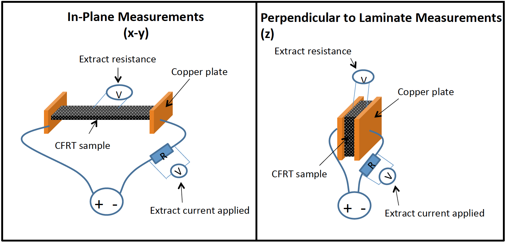
- Electrical resistivity can be over 1000x greater perpendicular to the laminates vs in-plane with laminate.
- Woven structures are pursued in this study due to availability and more favorable properties for induction (generally lower resistivity and more isotropic).
Joining Technique Comparison
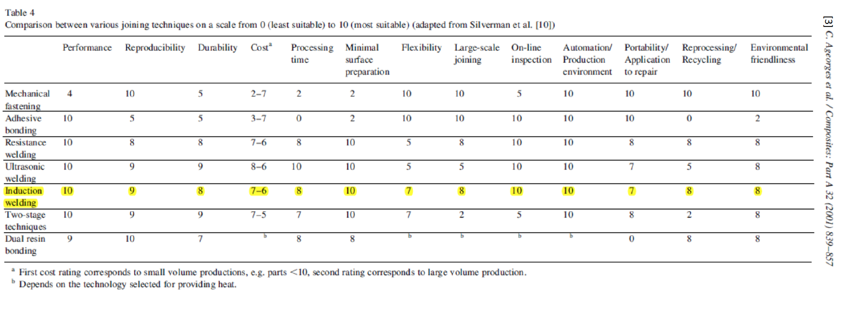
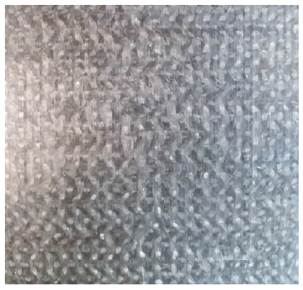
Materials Investigated
- 3k & 6k Toray T300 carbon fiber, 44% PET Resin, 2x2 twill co-weave, (0/90)/(+45/-45)
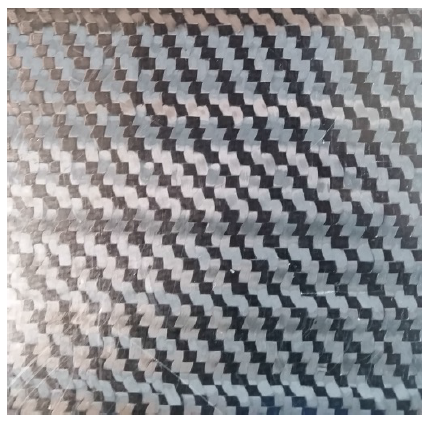
- 3k Toray T300 carbon fiber, 45% PEI resin, 8 harness-satin type non-symmetrical co-weave, (0/90)
Direction-Specific Electrical Resistivity Measurements
In-Plane Equivalent Resistivity
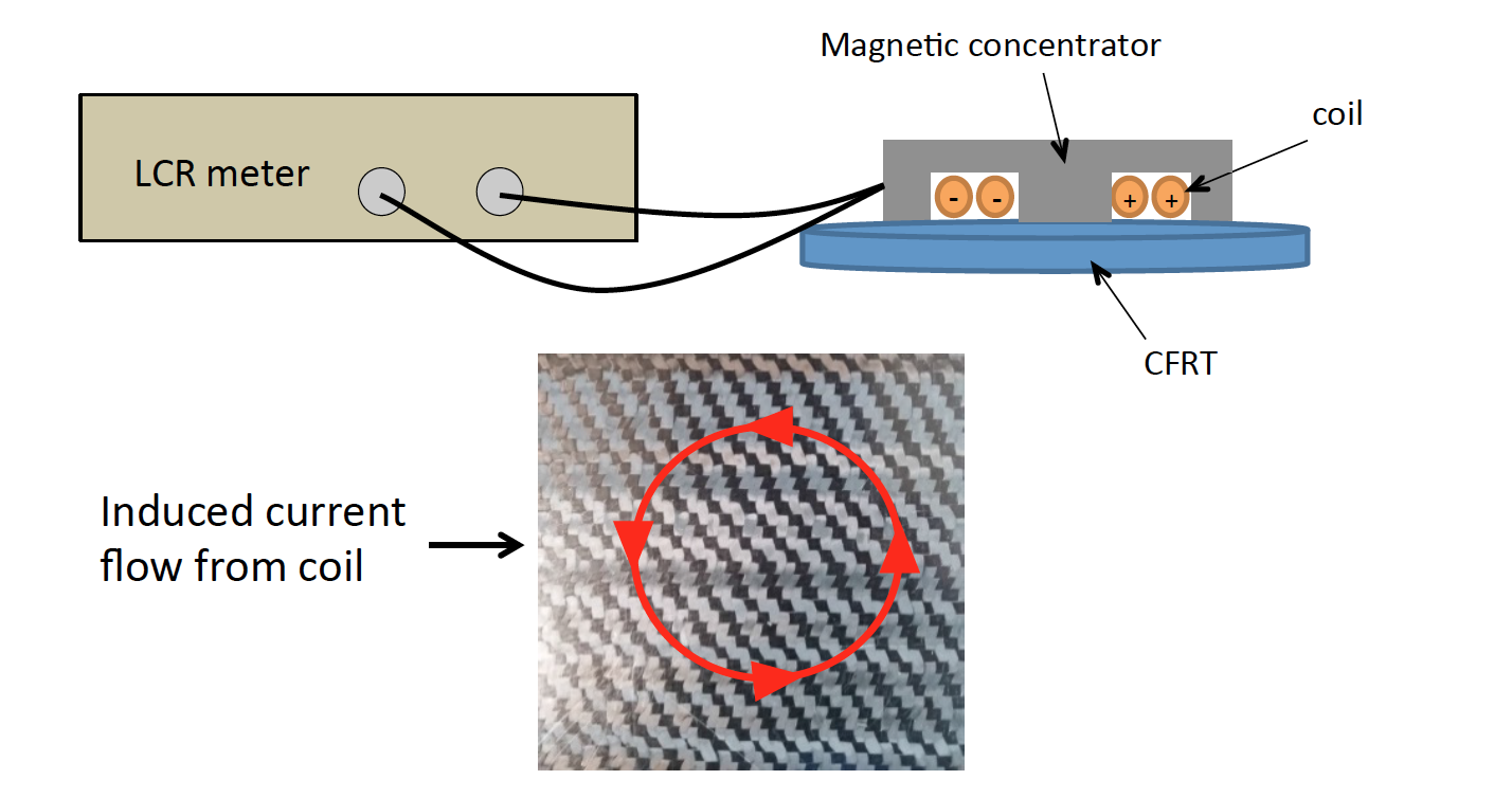
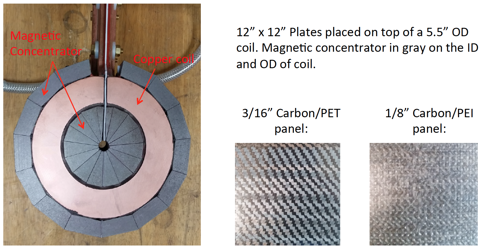
Impedance measured performed with coil only and with CFRT below coil.
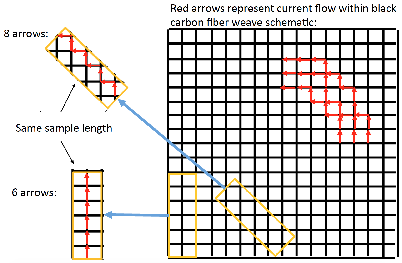
Provides an equivalent resistivity for all directions in-plane. Induced current path illustrated above.
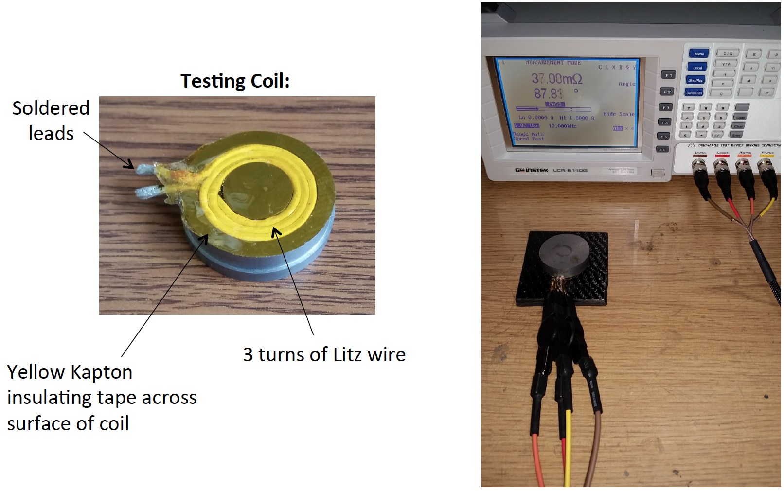
Equivalent Resistivity Test Set-Up
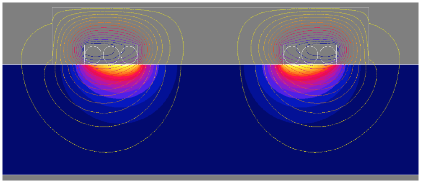
Equivalent Resistivity Extraction via FEA
- The measurement coil is modeled axisymmetrically in electromagnetic FEA software Flux 2D.
- The impedance of coil without a load is matched to experiments.
- Electrical resistivity is determined by matching the measured impedance with the CFRT load.
- Magnetic field lines and power density in a ½” layer of the material is displayed in the figure on right.
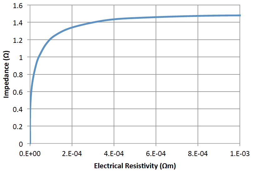
Electrical Resistivity Results
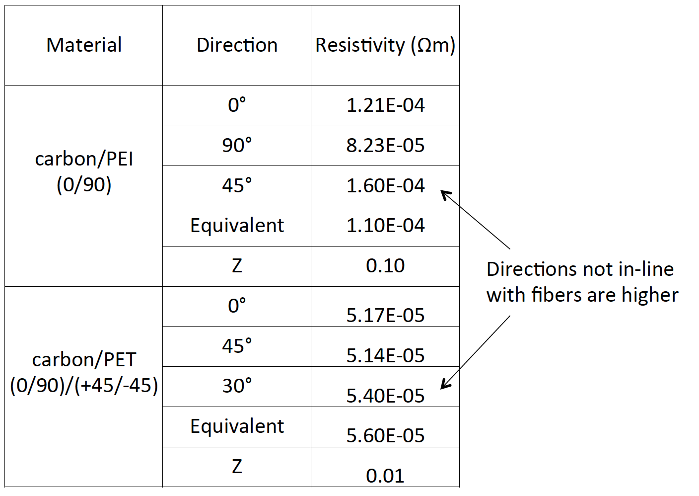
Measurement vs Performance
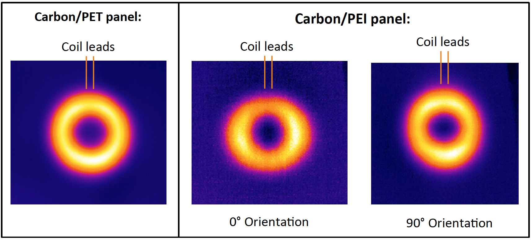
Thermal Behavior
Thermal Images from IR Camera
Computer Simulation
- A simple lap joint of two 1/8” CFRT panels is modeled using FEA to represent a welding application.
- 2D and 3D cross-sections are examined with different coil designs.
Dimensions of Lap Joint Used in FEA Simulations
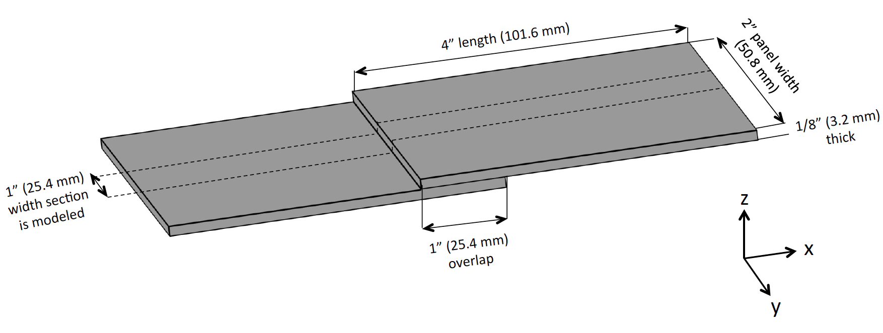
- Other surrounding components such as pressure applicators are not considered.
- Components between the coil and joint should not be conductive or magnetic, therefore transparent to magnetic field.
- Components in contact with the joint will affect the thermal distribution.
Frequency Selection
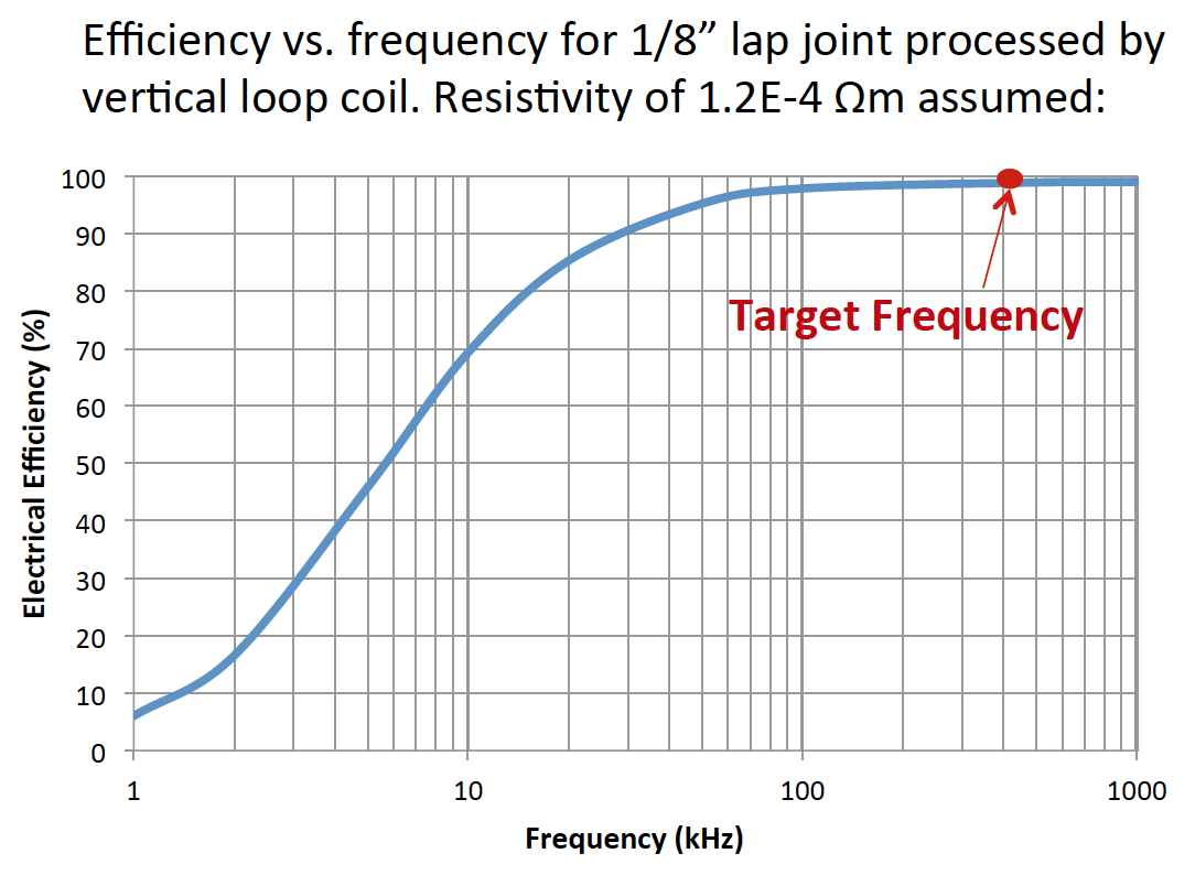
400 kHz is chosen for this study based on:
- Efficiency levels out around this frequency for 1/8” panels
- Wide range of power equipment availability
- Voltage remains manageable
- No restrictions by FCC
- Dielectric heating of matrix material can be neglected, as it is difficult to predict
Two Turn Oval Style Coil
Oval Coil Current Density
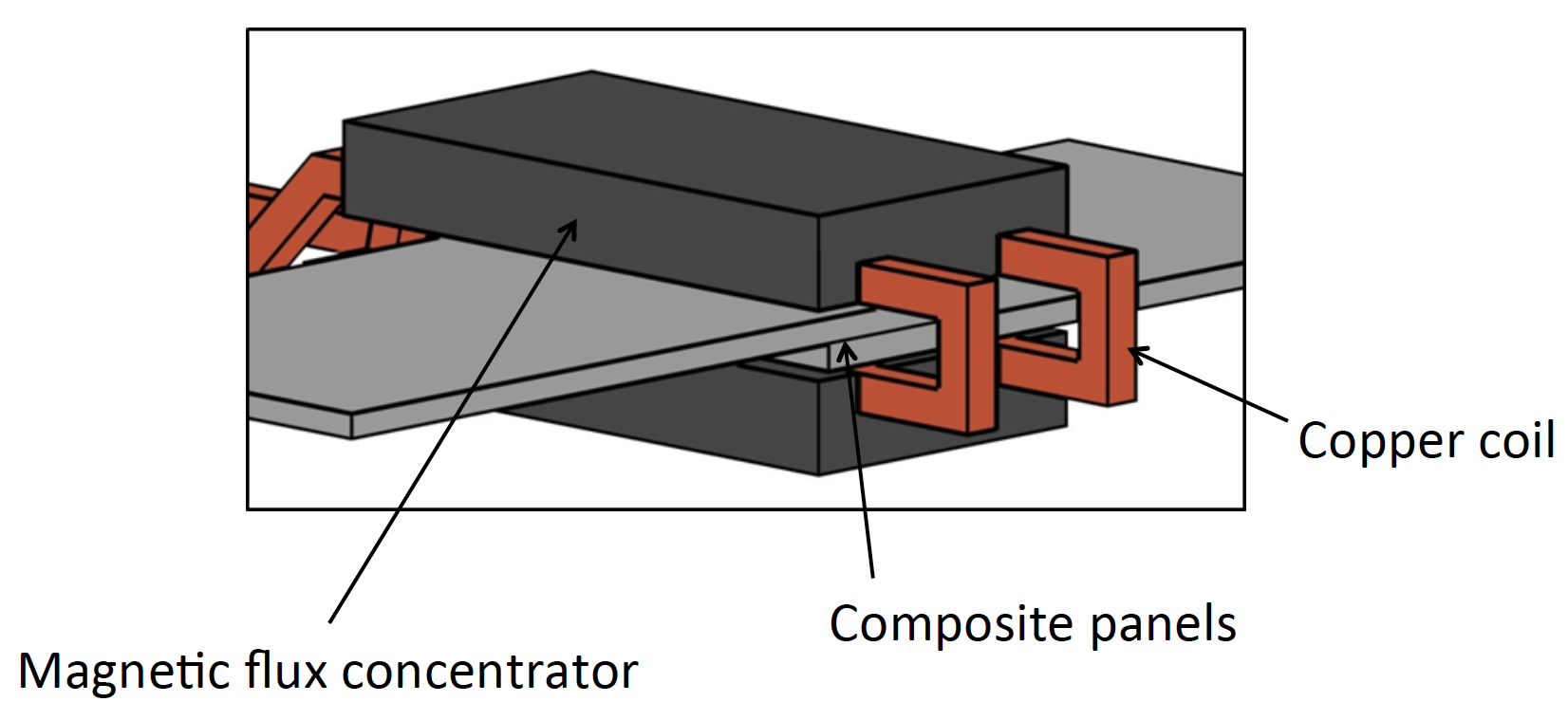
Two Sided Vertical Loop Style Coil
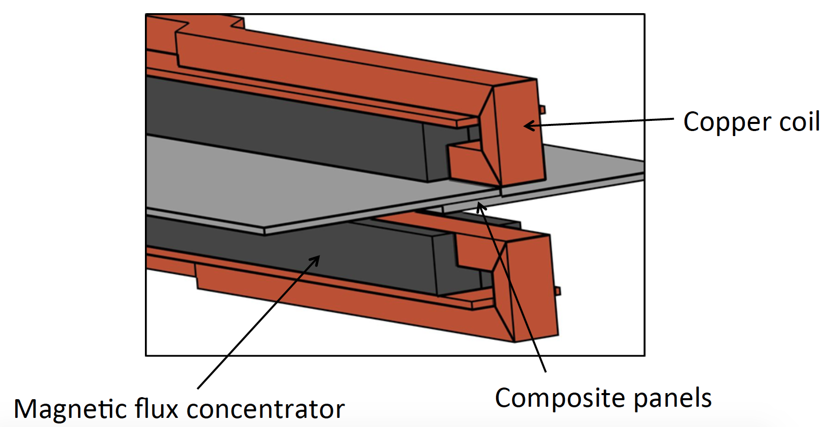
One Sided Vertical Loop Coil
Current Density
Two Sided Vertical Loop Coil
Current Density
Summary
- Induction is a contactless method for heating CFRT’s that can be controlled by process parameters and coil design.
- Carbon fiber reinforced thermoplastics (CFRT) can have a large variation in electrical properties depending on the carbon fiber arrangement, matrix material, lay-up schedule, etc.
- Woven CFRT can be isotropic in one plane or be completely anisotropic. Unidirectional lay-ups will be completely anisotropic for the most part. This makes the thermal performance difficult to predict with the induction method.
- Methods have been described to determine the direction-specific and equivalent electrical resistivity of CFRT.
- FEA can be used to aid in the prediction of heating CFRT for various coil designs.
- It is shown that frequencies below the MHz range has effective performance and is easier to utilize with a wide range of coil and equipment design. Components of larger dimensions may show more benefit at even lower frequency.
References
- 1. Ahmed T.J., Stavrov D., Bersee H.E.N., Beukers A., Induction Welding of Thermoplastic Composites-An Overview, Netherlands, Composites: Part A, Vol. 37, 1638-1651, 2006
- 2. Caretto F., Studying the “Induction Welding” Process Applied to Thermoplastic-matrix Composites, ENEA, Italy, EAI; 103-111, 2011
- 3. Ageorges C., Ye L., Hou M., Advances in Fusion Bonding Techniques for Joining Thermoplastic Matrix Composites: A Review, Australia, Composites: Part A, Vol. 32, 839-857, 2001
- 4. Jackowski J., Goldstein R., Nemkov V., Induction Process and Coil Design for Welding of Carbon Fiber Reinforced Thermoplastics, SAMPE Tech 2014
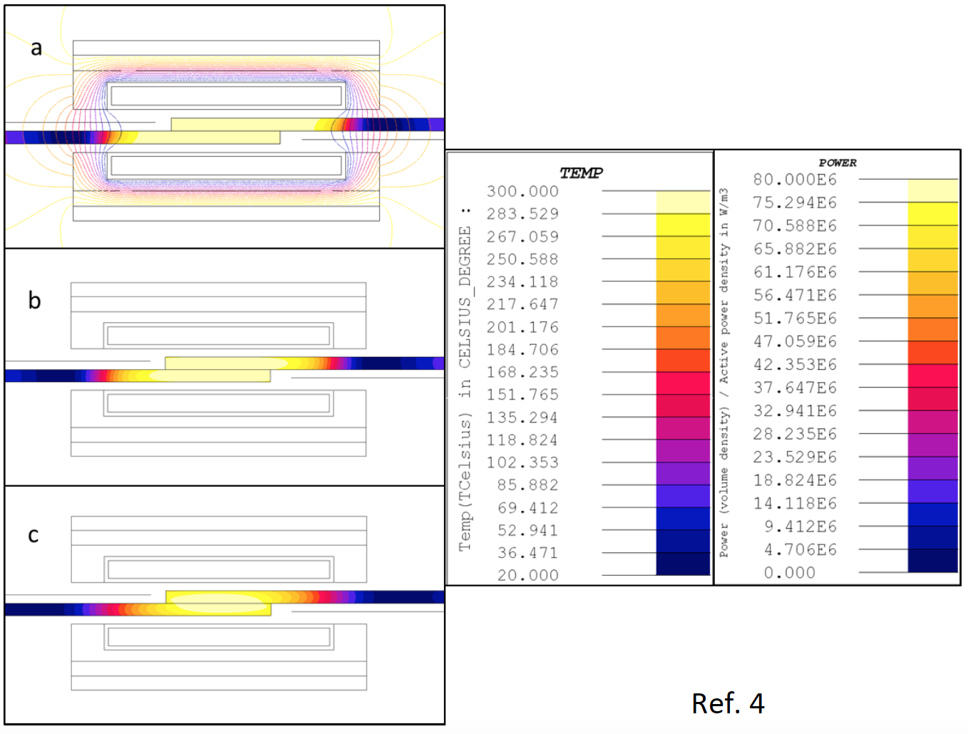
Power density (a), and temperature at end of 5 second ramp up (b) and 10 second hold (c) at 2 MHz
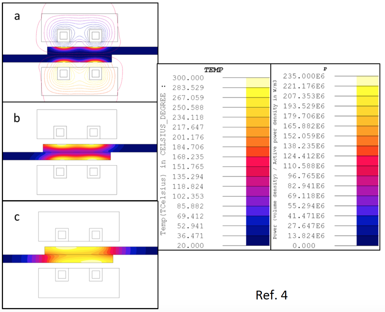
Power density (a), and temperature at end of 5 second ramp up (b) and 10 second hold (c) at 300 kHz
If you have more questions, require service or just need general information, we are here to help.
Our knowledgeable Customer Service team is available during business hours to answer your questions in regard to Fluxtrol product, pricing, ordering and other information. If you have technical questions about induction heating, material properties, our engineering and educational services, please contact our experts by phone, e-mail or mail.
Fluxtrol Inc.
1388 Atlantic Boulevard,
Auburn Hills, MI 48326
Telephone: +1-800-224-5522
Outside USA: 1-248-393-2000
FAX: +1-248-393-0277