Information
Authors: Robert C. Goldstein, John K. Jackowski, Valentin S. Nemkov
Location/Venue: IFHTSE 2014
Topic: Carbon Fiber Reinforced Thermoplastics
Download Presentation PDF
Abstract
Being contactless and volumetric, induction heating has proven to be an effective method for producing high strength weld joints between Carbon Fiber Reinforced Thermoplastic (CFRT) components. There are inherent challenges with the implementation of this technology due to the anisotropic nature of CFRT. The anisotropic electrical and thermal properties of CFRT plate are described. The properties are inputted to a FEA program for electromagnetic and thermal simulation. The program is used to design an induction coil with a goal of achieving uniform temperature distribution in a lap joint between two CFRT plates. Effect of frequency, material orientation, and coil design is examined.
Introduction
Induction is an established method for heating of carbon fiber reinforced polymers. Induction offers a clean, fast, and efficient method for heating that integrates well into a mass production line. While autoclave is the leading method for thermal processing of CFRT, induction is an emerging alternative. Alternating magnetic fields are used to induce eddy currents in the load (in this case carbon fiber), making it contactless by nature and local to where the field is applied. Depending on the electrical and magnetic properties of the load and the frequency of the alternating field, the eddy currents can be induced volumetrically to produce heat within the bulk of the material. Other common methods such as resistance, infrared, or convection apply heat to the surface of the material and a significant time lag is required to reach the desired temperature in depth without overheating the surface. The benefits of induction and a comparison to other well-known heating methods are described by Da Costa et al. [1]. The focus of the studies in this report is intended for lap joint welding CFRT. For welding CFRT a joint interface temperature that exceeds the melting temperature of the polymer matrix is needed, along with applied pressure. Induction can also be used for tape placement/curing/consolidation, forming, repairing, and surface finishing of CFRT.
The main drawback to induction is the difficulty of generating uniform temperature at the weld interface, especially for larger geometries [2,3]. The coil design and process parameters have not been well examined when utilizing induction for CFRT. An in depth understanding of the technology is needed to consider the many effects and factors involved when targeting a certain thermal profile.
Induction heating is possible for CFRT only when there are closed loops for eddy current to flow. Current flowing along the carbon fibers must return back along another set of fibers. If there is a sufficient galvanic connection between the fibers due to their contact, a conductive loop is created. This is the scenario used for the examples in this paper, assuming the carbon fiber is in woven form. When there is insufficient fiber contact the only way for current to flow in a closed loop is to flow through the plastic due to capacitive coupling of carbon fibers. This can only happen at high frequencies (well within the MHz range for most polymers). In this case, additional heat generation can occur due to dielectric losses in the polymer [4,5]. In our case we completely neglect additional heating contributed by the polymer since the frequency range of interest is from .01-2 MHz. This assumption is supported by the findings of Rudolf et al. [6] and Miller et al. [7].
Metal mesh has been used to help provide uniform heat distribution at the joint interface. A thin metallic foil or layer of magnetic particles could also be used. With the proper coil design and process parameters, supportive heating components at the joint interface should be unnecessary for uniform heating of most geometries. Another method to aid in the weld formation is the application of a film insert of thermoplastic at the interface of the lap joint. This method could reduce required temperature and sensitivity to applied pressure or processing time. A lower temperature thermoplastic could provide a bond without structural deformation of the base material. However, no significant advantage to the interlaminar shear strength (ILSS) has been discovered by the application of major insert methods. A comparative table of previous studies by a wide range of research groups shows the results of various methods and corresponding ILSS. [8] This is further confirmed by the findings of Caretto [9].
The intent of this paper is to establish a foundation in understanding the net properties and heating behavior of CFRT, using the induction technique. Fundamental induction heating concepts are used to examine the response of this complex material and the impact proper coil design has on the heat distribution and process parameters. The application in focus is welding of a lap joint. More extensive material examination and experimental results are intended to follow in further studies.
Experimental Setup
Material Properties
The electrical and thermal properties of CFRT are needed for predicting induction heating performance. These materials’ properties are difficult to characterize due to their anisotropic nature. The unidirectional plies in a quasi-isotropic laminate complicate this further since properties can vary in all three dimensions and the net heating phenomenon is more difficult to predict. For this study, a woven carbon fiber fabric reinforcement is selected to allow two-dimensional assumptions to be made. The electrical resistivity in plane (parallel to fibers) and in through-thickness (perpendicular to fibers) is taken from the study of Rudolf et al [6], and is displayed in Table 1. The material is a 5-harness satin carbon fiber fabric reinforced polyphenylensulfide, 46% fiber by volume. The thermal conductivity, specific heat capacity, and density are determined by using the rule of mixtures. The individual material properties and equivalent composite properties are given in Table 1.
| Material | PPS | T300 carbon fiber | Composite |
|---|---|---|---|
| Orientation | Parallel | Perpendicular | |
| Volume fraction* | 0.54 | 0.46 | 1 |
| K (W/mk) | 0.29 | 10.5 | - |
| Keq (W/mk) | 5 | 0.5 | |
| Cp (J/kgK) | 1000.70 | 795.50 | - |
| Cpeq (J/kgK) | 906.3 | 906.3 | |
| d (g/cm3) | 1.35 | 1.76 | - |
| deq (g/cm3) | 1.54 | 1.54 | |
| ρ (Ωm)* | 5.0E-04 | 3 | |
FEA Simulation
A proper coil design is examined for welding two ⅛ inch (3.2 mm) thick by 4 inch (101.6 mm) long panels with a 1 inch (25.4 mm) overlap. The width requirement of specimens to meet standard ILSS testing criteria is 1 inch, but for the two-dimensional analysis the width of the panels is considered infinite. The electrical parameters relate to a 1 inch section out of an infinitely wide system. Any edge effects of the current in the third dimension are neglected. If the panel width is less than about 6 times the penetration depth (δ), then assumptions made about the electrical parameters of the section in an infinite system are no longer valid. The dimensions of the specimen used for FEA is shown in Figure 1.
The coil cross-section is modeled with 3/16 inch (4.8mm) square tube for all cases other than the vertical loop style coil, which has a tube width of 2.2 inches (55.8 mm). Ferrotron 559H magnetic concentrating material is included for all cases and a coupling gap of 1/8 inch (3.2 mm) is used.
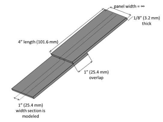
Figure 1: Dimensions of test specimen used in FEA.
Electromagnetic-thermal coupled software, Flux 2D, is used for predicting the heat response of the joint of proposed test specimens. This software is a useful tool for the examination of frequency dependence, fiber orientation, and coil design effect on the sectional heat profile. It is a reliable method for the accuracy and efficiency of developing the induction process and coil design [10,11]. The maximum temperature in the composite was consistent for all models at 300 °C, considering the melting temperature of PPS is around 280 °C. If the lap weld interface is heated at an equal or higher ramp rate than the surface, the overall time to temperature can be reduced. For this reason 5 seconds is targeted in the models to reach 300 °C. Otherwise if the surface is at a higher temperature than the interface a longer ramp up time will be needed to avoid overheating the surface. After the 5 second ramp up, the maximum temperature is held for 10 seconds (a total heat time of 15 seconds) and in certain cases 60 seconds (total heat time of 65 seconds), to simulate the time needed at pressure for a complete weld. In a real process uniform pressure will need to be applied to the weld zone, therefore requiring direct contact of external components to the test specimens. For a fundamental comparison, other surrounding components were not considered in the simulation results. Instead ambient heat loss conditions were applied to all surfaces.
Results
Frequency Dependence and Penetration Depth
Penetration depth is a parameter that describes the depth from the heating surface that the majority of eddy currents exist. The penetration depth is dependent on the electrical and magnetic properties of the material and the frequency. Magnetic permeability is not a factor for CFRT since both carbon and thermoplastics are non-magnetic. The penetration depth (δ in m) then becomes a function only of resistivity (ρ in Ωm) and frequency (f in Hz) according to the relation in equation 1, where k = 503.

Considering a total thickness at the weld overlap of ¼ inch (6.35 mm), the ratio of this thickness to penetration depth with frequency is plotted in Figure 2 by the curve labeled “1/8” panels”. The resistivity listed in Table 1 for parallel orientation is applied. Three other panel thicknesses are also plotted for examples of what depth of heating to expect at various frequencies. When the ratio of thickness to penetration depth (t/δ) increases, a larger thermal gradient in depth will result for one-sided heating. However, the electrical efficiency will reach a maximum when t/δ is large enough. Figure 3 shows the electrical efficiency for the hairpin style coil displayed in Figure 4. The efficiency tends to level out above 1 MHz. The relation of frequency to efficiency will depend heavily on the coil design such as: coil style, tube size, tube spacing, coupling gap, and concentrator placement. For example, the effect of tube spacing on efficiency for a hairpin coil is illustrated in Figure 3. The curve labeled “.34” Spacing” represents the case used in the results of Figure 4. For this example, as frequency is lowered below 2 MHz, the temperature gradient from the heating surface to joint interface will decrease some, but efficiency will drastically drop and eventually a point can be reached where no significant heating will occur (below 10 kHz for this case).
There is no saying that low efficiency scenarios are out of the question. If the induction system design is limited to one-side heating only, lower frequency will improve the thermal uniformity of the weld. If thermal performance is more critical than the concern for power consumption, then frequencies as low as 10 kHz could be feasible for 1/8” panel thickness. From the standpoint of the induction equipment design, frequencies below 1 MHz are more desirable. Above this range, there is lower availability of induction heating power supplies. There is also a concern of interfering with high frequency communication systems that could violate FCC regulations.
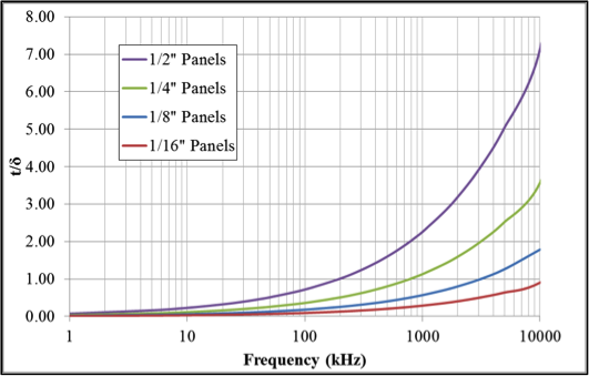
Figure 2: Ratio of thickness to penetration depth vs log of frequency for various thicknesses of CFRT panels.
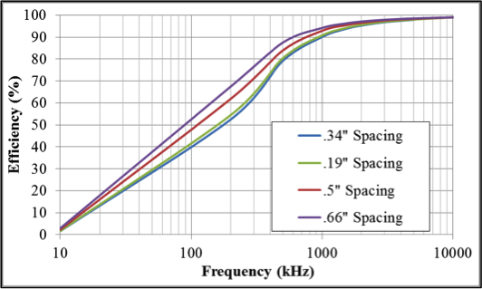
Figure 3: Electrical efficiency vs log of frequency for one-sided hairpin coil at various turn spacing.
A one-sided hairpin style coil is considered for analyzing frequency and time at temperature on the thermal profile of the weld. The temperature distribution in the CFRT specimen is compared at 200 kHz (t/δ = .25), 2 MHz (t/δ = .8), and 10 MHz (t/δ = 1.8) in Figure 4. The temperatures on the left are shown after a 5 second ramp up to reach a maximum temperature of 300 °C. The temperatures at the center and right of the figure are after a 10 second hold and 60 second hold respectively, at the maximum temperature. The depth of heat through the joint is noticeably larger at 2 MHz compared to 10 MHz at end of ramp up, while the efficiency is nearly unchanged (95.3% at 2 MHz, 98.7% at 10 MHz).When lowering frequency to 200 kHz, the depth of heat is even greater, but the efficiency is reduced to 52.6%. Considering the desired temperature distribution while maintaining decent efficiency, 2 MHz is a reasonable choice in frequency. After 60 seconds of hold at the maximum temperature, the heat distribution is near equilibrium and the temperature at the interface reaches a maximum within 20 °C of the target for 2 MHz. This means the surface will have to exceed the target temperature by about 20 °C after a 60 second hold to reach 300 °C at the interface.
With respect to the processing time and slight excess in surface temperature for the hairpin coil, this design may not be ideal. The one major benefit to one-sided heating is accessibility. There may be instances where heating from both sides is impossible due to machine or part interferences. For these cases one-sided heating is still a practical option, however heating times on the order of minutes should be expected. Even so, process time will be shorter than many alternative heating methods.
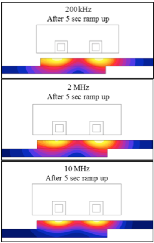
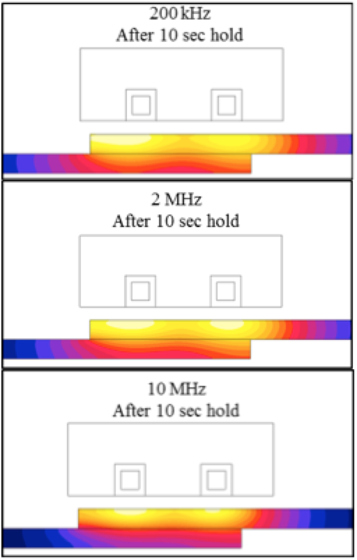
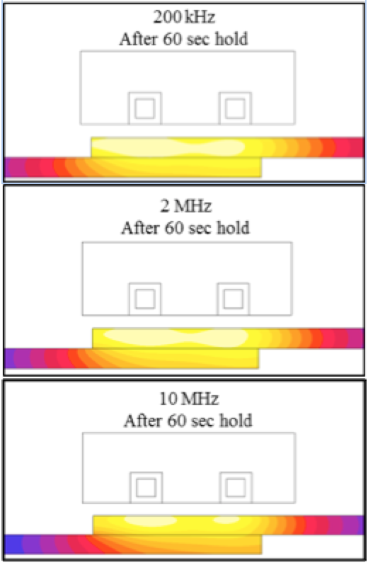
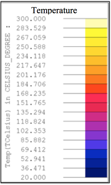
Figure 4: Temperature distribution at end of 5 second ramp up, 10 second hold, and 60 second hold for a one-sided hairpin coil at 200 kHz, 2 MHz, and 10 MHz.
Material Orientation
There needs to be a continuous electrical path within the material to observe Joule effect heating. To illustrate the differences between the resistivities of parallel versus perpendicular orientations, unidirectional fibers are represented in the test specimen geometry. Assuming electrical resistivity in the direction parallel to the fibers, efficient heating is achieved. The power density resulting from a hairpin style coil in this direction is displayed in Figure 5a. When the resistivity in the perpendicular direction is applied to the same situation, no power is induced, as shown in Figure 5b. In reality for an entirely unidirectional material, the current will have to travel through the matrix material from fiber-to-fiber in the third dimension not shown. This third-dimensional effect could reduce the net efficiency of the heating, or if frequency is low enough, will prevent heating all together for a unidirectional material. In a quasi-isotropic material with cross-plies or angle-plies of unidirectional tape, this effect needs to be considered in all three dimensions and the net heating properties will vary even further. The remainder of the two-dimensional models are under the assumption that the CFRT is woven and each individual layer has good electrical contact between all fibers.
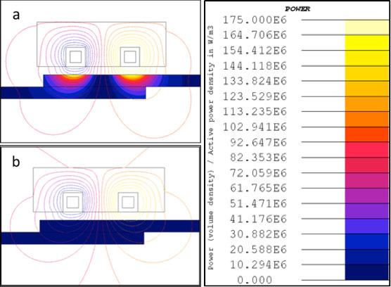
Figure 5: Power density and magnetic field lines for resistivity in parallel direction (a) and perpendicular direction (b) at 2 MHz
Coil Design
For the given specimen geometry there are many coil styles that can be applied to induce various eddy current paths in the material. Each coil style will produce a different thermal profile in the joint and has different electrical parameters. Coil design is only limited by the need to complete the current loop from the power source. The design options are almost endless, but most coil designs can be broken down into a common “style” of coil.
One-sided heating was initially investigated with a hairpin style coil. There is an inverse relation of electrical efficiency and temperature uniformity in thickness for one-sided heating. Two-sided heating may be more difficult to implement due to accessibility reasons, but for targeting uniform temperature at the joint interface in a short amount of time and keeping power demand low, two sided heating is desired. The coil styles investigated for two-sided heating are oval, transverse flux, and vertical loop.
Two Turn Oval Style
A coil wrapped around the width of the CFRT specimens (oval style) is considered. This encircling/longitudinal flux style of coil will produce opposing magnetic field on either side of the weld. The field will penetrate the material, aligned parallel with the heat surfaces. With this configuration there will be no current traveling along the weld interface which can be seen by the power density distribution of Figure 6a. The electrical efficiency will tend to be low due to the cancellation of induced currents. The highest temperatures will be on the surface of the material with a relatively steep decline to the joint. Figure 6b shows the large gradient after a 5 second ramp up. A hold at temperature is very beneficial to the equalization of temperature near the joint, as shown in Figure 6c, after a 10 second hold. The current must return from one panel to the other, perpendicular to the joint interface with this style of coil. This may pose a challenge to maintain good contact from panel-to-panel to allow current to return between. Local overheating at the ends of the specimen will be a concern due to the high power density from current flowing in three directions.
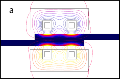
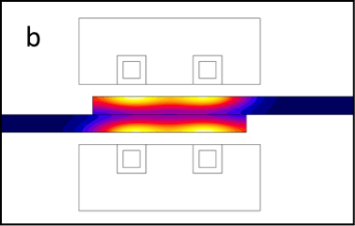
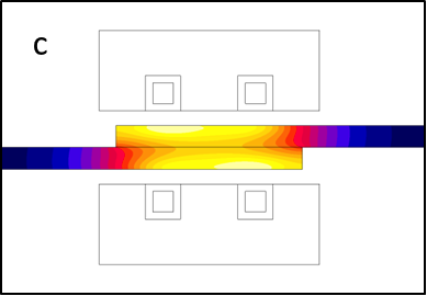
Figure 6: Power density and magnetic field lines (a) and temperature distribution at end of a 5 second ramp up (b), and 10 second hold (c) from oval style coil at 2 MHz.
Transverse Flux Style
This coil design is similar to the hairpin coil, but applied to both sides of the specimen to create a transverse magnetic flux flow. For manufacture of this coil, the turns on each side would both be wrapped in the same direction. In this configuration the majority of current will be induced near the ends of each panel of the overlap and no current will exist in the center (Figure 7a). The magnetic field will pass through the specimen perpendicular to the heat surfaces. The heat pattern for this style of coil will result in a cooler region at the center of the weld zone during ramp up (Figure 7b). After a 10 second hold (Figure 7c), the heat distributes much more uniformly, the center of the weld fills in, and a large portion of the interface is near the target temperature.
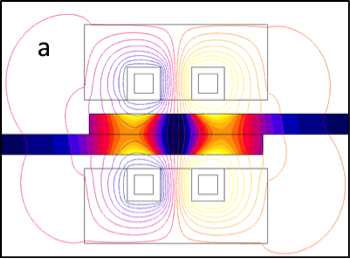
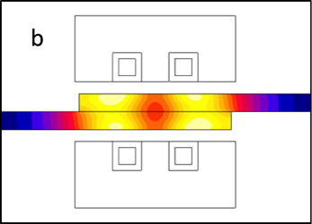
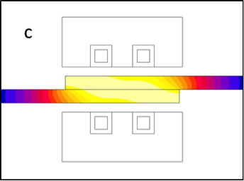
Figure 7: Power density and magnetic field lines (a) and temperature distribution at end of a 5 second ramp up (b), and 10 second hold (c) from transverse flux style coil at 2MHz.
Two-Sided Vertical Loop Style
A vertical loop style coil induces the desired current in one direction along the width of the lap joint. The current in the heat face of the coil is returned on the backside of the main heating leg, which does not contribute much to the direction of return current in the part. The eddy current will split at the end of the width of joint to be heated and naturally forced to return on either side of the overlap, creating a so called “butterfly” pattern. When applying a vertical loop on both sides of the specimen in the same orientation, eddy currents can be generated uniformly throughout the cross-sectional area of the overlap. The current is then forced to return on either side of the joint, but more spread out (as long as there is sufficient panel length). The return current will add some heat outside of the weld zone, but it will be minimal due to the low intensity of the current.
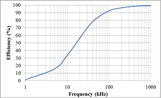
Figure 8: Electrical efficiency vs log of frequency for two-sided vertical loop coil at 300 kHz.
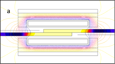
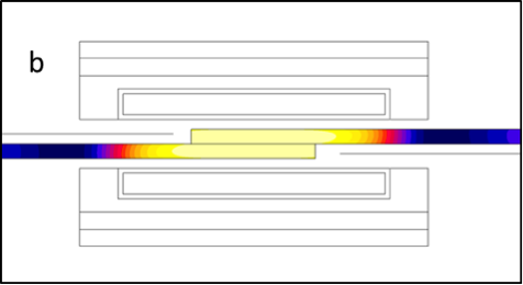
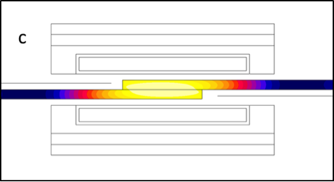

Figure 9: Power density and magnetic field lines (a) and temperature distribution at end of a 5 second ramp up (b) and 10 second hold (c) from a vertical loop style coil at 300 kHz.
The efficiency versus frequency for this coil design is shown in Figure 8. Optimal efficiency is at lower frequencies than with the previous designs since the cancelation of current in the weld zone is not a concern. Frequency will not have as large effect on the heat distribution as the previous designs. The efficiency levels out around 300 kHz for this case, which is applied to the models of Figure 9. Due to the uniformity of power in thickness of the overlap (Figure 9a), the resulting temperature in the weld zone has a high degree of uniformity after ramp up (Figure 9b). The highest temperatures are at the weld interface which is why a hold at temperature actually reduces the uniformity from conduction in length and surface losses (Figure 9c).
Comparative Review of Coil Designs
The temperature along the 1 inch weld interface for the hairpin and oval coils are shown in Figure 10. There are three profiles for each coil: 5 second ramp, 10 second hold, and 60 second hold. Both of these coil designs have a large temperature gradient from surface to interface after 5 seconds of heat. An additional 10 seconds of holding the maximum temperature has a significant effect in raising the interface temperature and smoothing the distribution, especially for the hairpin coil. After 60 seconds of hold, the distribution is near equilibrium and the maximum temperature is within 20 ºC of the target for both coils.
The interface temperatures for the transverse flux and vertical loop coil are in Figure 11. The distribution from the transverse flux coil levels out drastically after a 10 second hold and is very close to the target temperature. 300 ºC is reached at the interface with only an additional 3 seconds of hold. The vertical loop coil results in a 25 ºC difference across the 1 inch length after 5 seconds. The central 60% of the length is maintained at 300 ºC. Out of the coils examined, this is the only design where thermal uniformity is reduced with additional time at temperature. If accessibility is not an issue, the two sided vertical loop coil is ideal for rapidly reaching temperature uniformity at the joint.
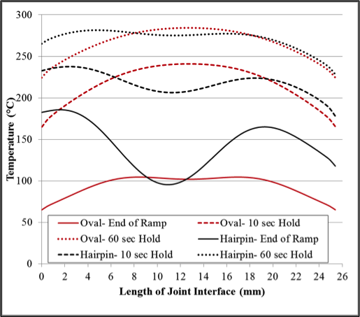
Figure 10: Temperature distribution along the weld joint interface for the hairpin and oval coils after a 5 second ramp up, after a 10 second hold, and after a 60 second hold.
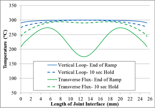
Figure 11: Temperature distribution along the weld joint interface for the transverse flux and vertical loop coils after a 5 second ramp up and after a 10 second hold.
The performance parameters of the major coil designs previously discussed are listed in Table 2. The values listed are of a 1 inch coil length, not including the cross-over sections or leads to a power supply. For this reason the power and voltage values shown are lower than would be for a complete coil. The values for power and voltage are per inch of width (refer to Figure 1) as long as the width of the entire system is greater than 6δ. All values are taken under the conditions of reaching 300 ºC in 5 seconds.
A magnetic concentrator material (Ferrotron 559H) was included for all cases examined due to its benefits in electrical efficiency and containing heat local to the welding zone. The benefits and uses of magnetic concentrating material are further described by Nemkov et al. [12] and Ruffini et al. [13]. For the hairpin coil and vertical loop coil, the parameters are compared to the absence of magnetic concentrator for the same maximum temperature in the specimen of 300 ºC. When the concentrator is removed from the hairpin coil, the power demand increased by 25%. Although the maximum temperature at the joint increased some. This is because the power distribution is widened without concentrator, so more power is put in to reach the same overall maximum temperature. When the concentrator is removed from the vertical loop coil, the efficiency drops to 54.4%, therefore increasing the total power demand by 86% and the apparent power by over ten times; current being the largest contributor. The lack of concentrator on the vertical loop makes the design almost infeasible. Apart from the increased performance that concentrator gives, this material also has a shielding effect to prevent the coil from heating surrounding components in a machine, which is not considered in this study.
The design with greatest efficiency without exceeding 2 MHz is the two-sided vertical loop at 98.2%. The maximum temperature is held across almost the entire overlap area, so the power requirement is larger than the other coil styles. As the frequency is increased the efficiency will approach near 100% for all the designs. The drawback being a larger thermal gradient will exist from surface to interface, which will result in longer processing times to reach sufficient weld temperature uniformity.
| Coil | Hairpin | Hairpin | Hairpin | Hairpin | Solenoid | Transverse Flux | 2-Sided Vertical Loop | 2-Sided Vertical Loop |
|---|---|---|---|---|---|---|---|---|
| Concentrator | yes | no | yes | yes | yes | yes | yes | no |
| f (kHz) | 2000 | 2000 | 200 | 10000 | 2000 | 2000 | 300 | 300 |
| Total P/in (W) | 193.7 | 242.4 | 399.6 | 125.9 | 215.7 | 304.5 | 804.7 | 1494.1 |
| Part P/in (W) | 184.6 | 229.6 | 210.2 | 124.3 | 168.4 | 290.7 | 790.6 | 812.2 |
| Efficiency (%) | 95.3 | 94.7 | 52.6 | 98.7 | 78.1 | 95.5 | 98.2 | 54.4 |
| Coil U/in (Vrms) | 22.3 | 19.6 | 21 | 32.2 | 63.6 | 36.3 | 18.8 | 20.1 |
| Coil Current | 48.4 | 110 | 403.8 | 18.3 | 78.5 | 40.1 | 189 | 1870 |
| Apparent P/in | 1.1 | 2.2 | 8.5 | 0.6 | 5.0 | 1.5 | 3.6 | 37.6 |
| Max Temp (C) | 300 | 300 | 300 | 300 | 300 | 300 | 300 | 300 |
| Max Temp at | 185 | 203 | 195 | 125 | 102 | 273 | 300 | 300 |
| Heat Time | 5 | 5 | 5 | 5 | 5 | 5 | 5 | 5 |
Conclusions
Proper process and tool design was examined for the intent of induction welding a lap joint of CFRT. A woven CFRT was chosen for simplicity of the study to allow 2D assumptions to be made. The FEA software Flux 2D was used to study the effects of material orientation, frequency, coil design, and use of magnetic concentrator. The targeted results were uniform temperature at the lap joint interface while not exceeding 300 ºC. The electrical efficiency, therefore power demand, was also considered. Joule heating was the only source considered in this study, based on net material properties of woven carbon fiber reinforced PPS. Surrounding components such as pressure application devices were not considered.
Heating intensity and distribution depends on the coil design, frequency, and material structure/orientation. Adjusting the frequency will impact the temperature distribution and electrical parameters. Ultimately, an optimal frequency can be found for every coil design that provides sufficient electrical efficiency without sacrificing too much in the thermal gradient of the weld.
Of the major coil styles examined, a two-sided vertical loop style coil with concentrator proved to have the best performance for quickly reaching thermal uniformity of the weld with high electrical efficiency. Good uniformity could be reached in the joint in 5 seconds (or less with added power). Sufficient thermal uniformity could be reached with the other coil styles after holding at temperature to allow heat to conduct through the material. A one-sided coil was investigated using a hairpin style. This coil provided uniform temperatures after a 60 second hold, but the target temperature would have to be slightly exceeded. Other one-sided style coils were not investigated, but could provide additional benefits. Heating from one side is the easiest to implement and may be the only option in some circumstances.
It was shown that induction is a very diverse technology. There are many options available for most applications. If well understood, the heating criteria for welding can be met for most CFRT applications. The most difficult aspect of induction is determining the best combination of coil design, frequency, and power setting. These are all things that FEA software is a great tool for aiding with.
More extensive studies are intended to be made on the feasibility of induction lap welding CFRT, using both simulation and experimental research. Methods for characterizing the fully anisotropic properties and predicting heat performance of a quasi-isotropic material will be pursued.
References
[1] Da Costa, A.P, et al., “A Review of Welding Technologies for Thermoplastic Composites in Aerospace Applications,” Journal of Aerospace Technology and Management, Volume 4, No. 3 (2012), pp.255-265.
[2] Ageorges, C., et al, “Advances in Fusion Bonding Techniques for Joining Thermoplastic Matrix Composites: A Review,” Composites: Part A, Vol. 32, (2001), pp. 839-857.
[3] Yousefpour, A., et al., “Fusion Bonding/Welding of Thermoplastic Composites,” Journal of Thermoplastic Composite Materials, Vol. 17, (2004), pp. 303-341.
[4] Fink B.K., et al., “Induction Heating of Carbon-Fiber Composites: Electrical Potential Distribution Model,” Weapons and Materials Research Directorate, ARL, University of Delaware, USA, 1999.
[5] Fink B.K., et al., “A local Theory of Heating in Cross-Ply Carbon Fibre Thermoplastic Composites by Magnetic Induction,” Centre for Composite Materials, University of Delaware, USA, CCM-Report, pp. 90-37, 1990.
[6] Rudolf, R., et al., “Induction Heating of Continuous Carbon-Fiber-Reinforced Thermoplastics,” Composites: Part A, Vol. 31, (2000), pp. 1191-1202.
[7] Miller, A.K., et al. “The Nature of Induction Heating in Graphite-Fibre Polymer-Matrix Composite Materials,” SAMPE Journal, Vol. 26, No.4 (1990), pp. 37-54.
[8] Ahmed, T.J., et al., “Induction Welding of Thermoplastic Composites-An Overview,” Composite: Part A, Vol. 37, (2006), pp. 1638-1651.
[9] Caretto, F., “Studying the “Induction Welding” Process Applied to Thermoplastic-matrix Composites,” EAI, (2011), pp. 103-111.
[10] Goldstein, R.C., et al. “Virtual Prototyping of Induction Heat Treating,” 25th ASM Heat Treating Society, Indianapolis, IN, 2009.
[11] Nemkov, V.S., et al., “Practical Use of Computer Simulation for Advanced Induction Coil and Process Design,” 5th ASM Heat Treatment and Surface Engineering in Europe, Sweden, 2000.
[12] Nemkov, V.S., “Magnetic Flux Control in Induction Installations,” International Conference on Heating by Electromagnetic Sources, Italy, 2013.
[13] Ruffini, R.T., et al., “Influence of Magnetic Flux Controllers on Induction Heating Systems, Computer Simulation and Practice,” 21st ASM Heat Treating Society Conference, Indianapolis, IN, 2001.
If you have more questions, require service or just need general information, we are here to help.
Our knowledgeable Customer Service team is available during business hours to answer your questions in regard to Fluxtrol product, pricing, ordering and other information. If you have technical questions about induction heating, material properties, our engineering and educational services, please contact our experts by phone, e-mail or mail.
Fluxtrol Inc.
1388 Atlantic Boulevard,
Auburn Hills, MI 48326
Telephone: +1-800-224-5522
Outside USA: 1-248-393-2000
FAX: +1-248-393-0277