Information
Authors: Robert Goldstein, Dr. Valentin Nemkov, Dr. Lynn Ferguson, Dr. Zhichao Li
Location/Venue: MS&T 2016
Introduction
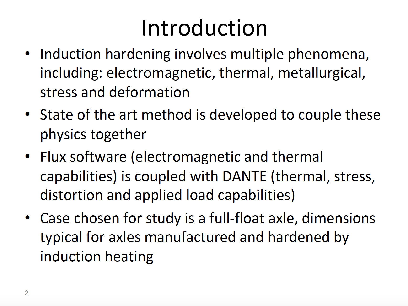
- Induction hardening involves multiple phenomena, including: electromagnetic, thermal, metallurgical, stress and deformation
- State of the art method is developed to couple these physics together
- Flux software (electromagnetic and thermal capabilities) is coupled with DANTE (thermal, stress, distortion and applied load capabilities)
- Case chosen for study is a full-float axle, dimensions typical for axles manufactured and hardened by induction heating
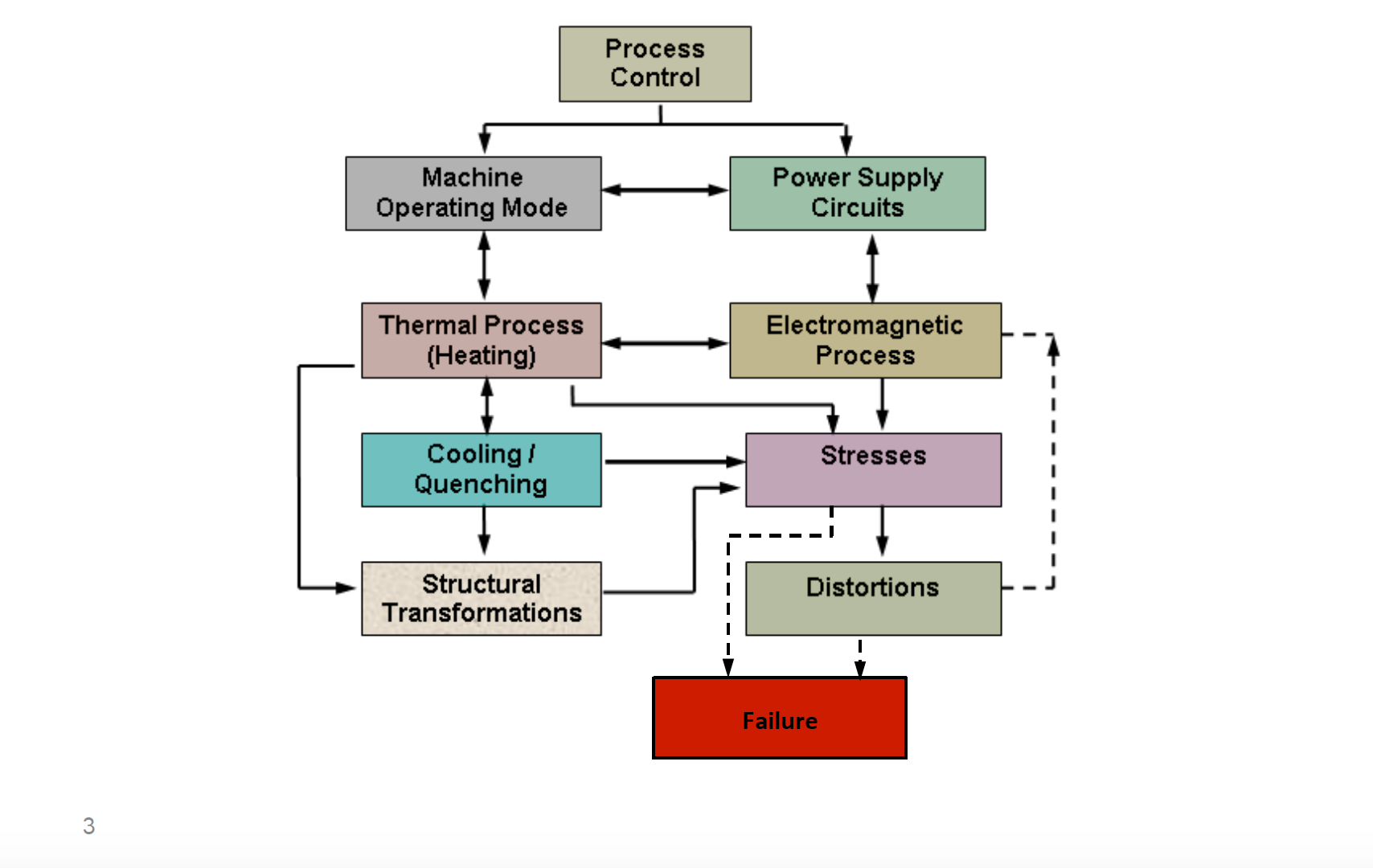
Mutually Coupled Phenomena in Induction Heating Process
Axle Dimensions Used in Model
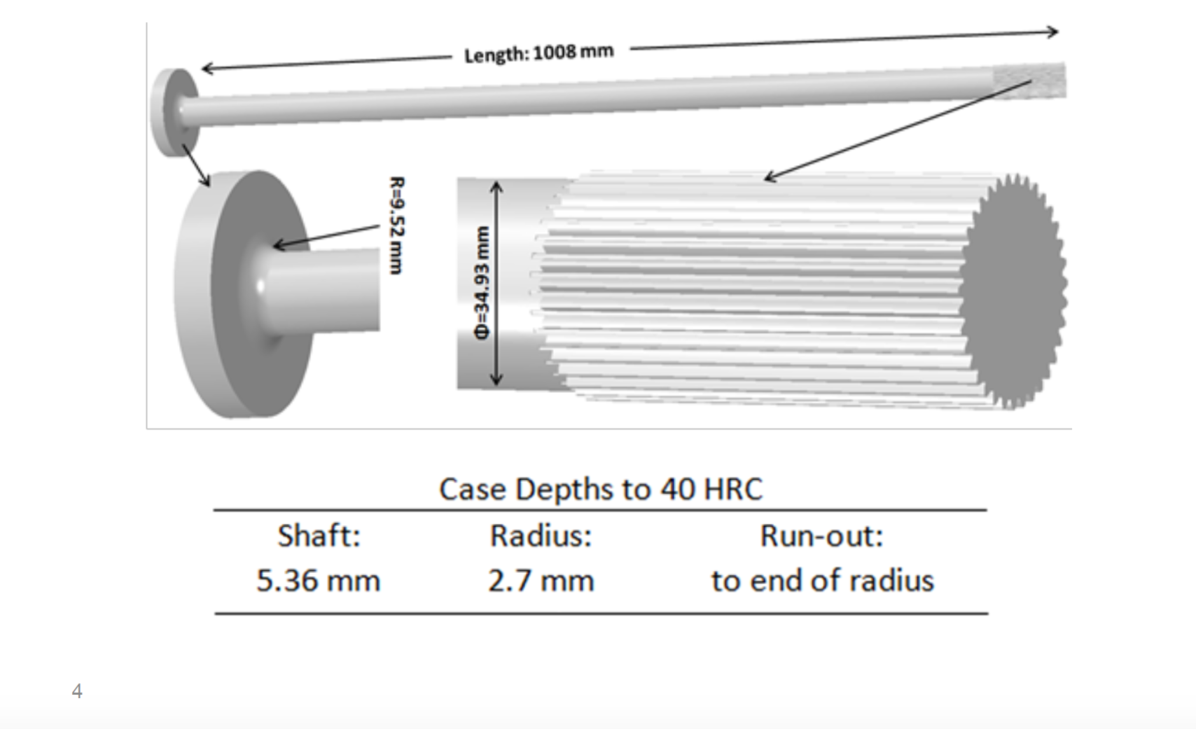
Axles can be broken into 3 main regions: Radius and Flange, Shaft, and Spline
| Shaft: | Radius: | Run-out: |
|---|---|---|
| 5.36 mm | 2.7 mm | to end of radius |
2-Turn Coil Design
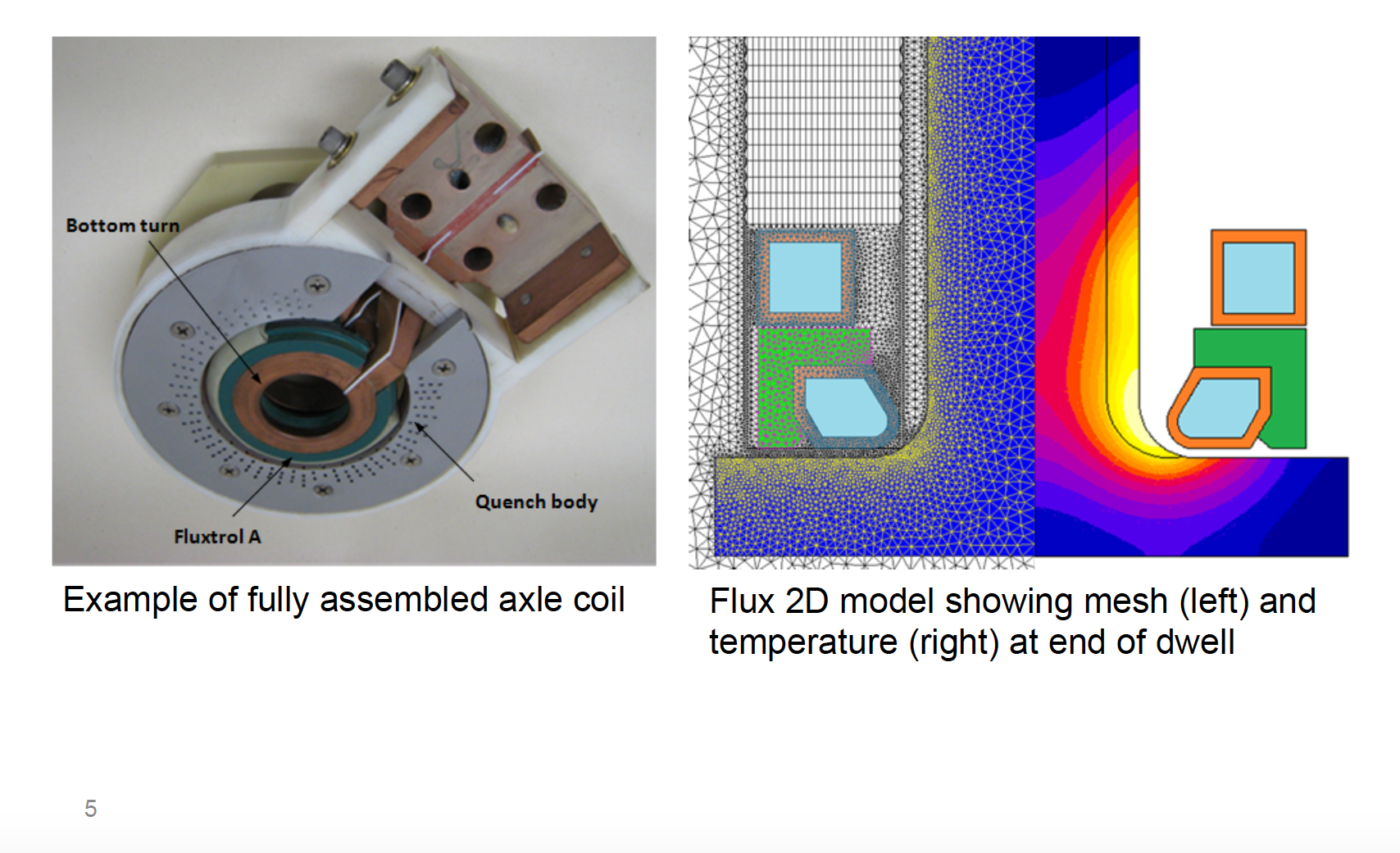
Figure 1 shows an example of a fully assembled axle coil. Figure 2 illustrates a Flux 2D model showing mesh (left) and temperature (right) at the end of dwell.
Due to Symmetry, Single Tooth of Spline is Modeled in DANTE
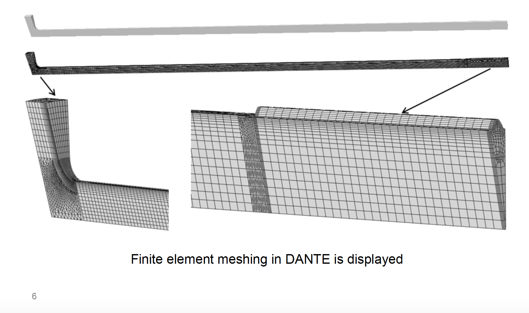
Finite element meshing in DANTE is displayed
Power Density in 3 Regions (Flux 2D)
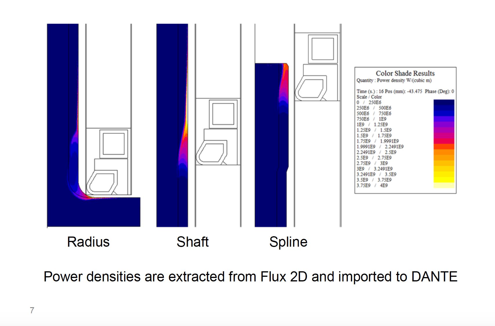
Power densities are extracted from Flux 2D and imported to DANTE
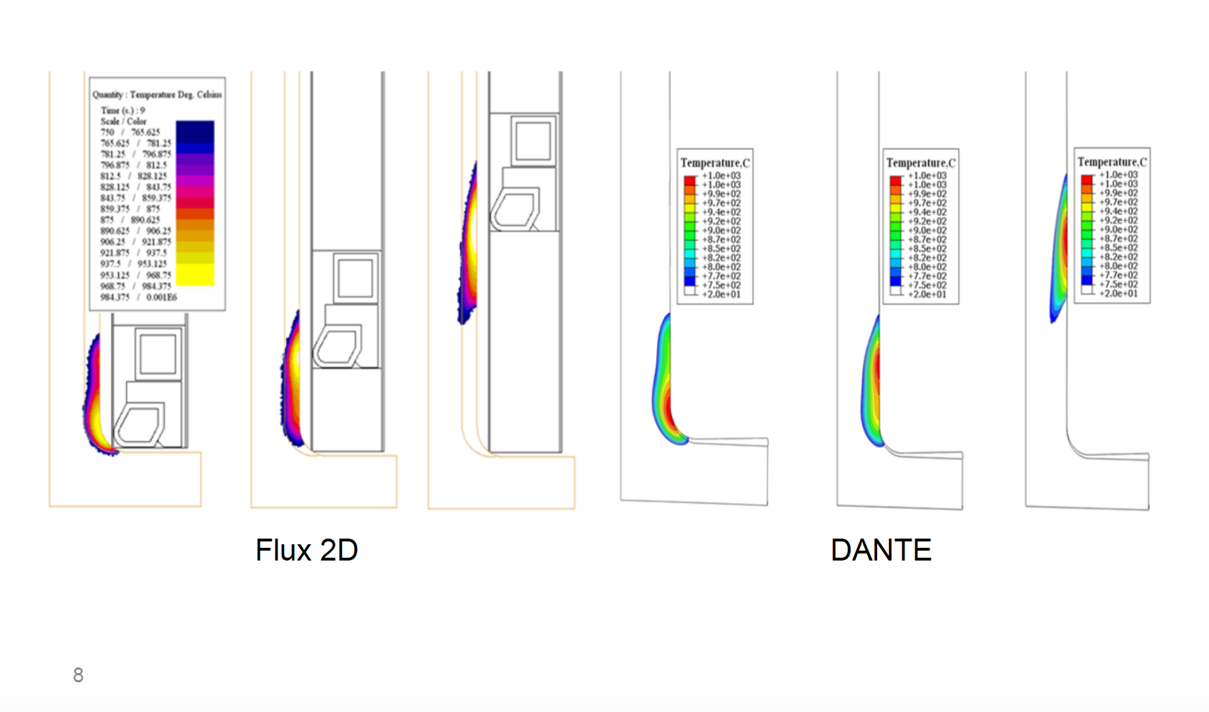
Temperature Validation Between Flux and DANTE
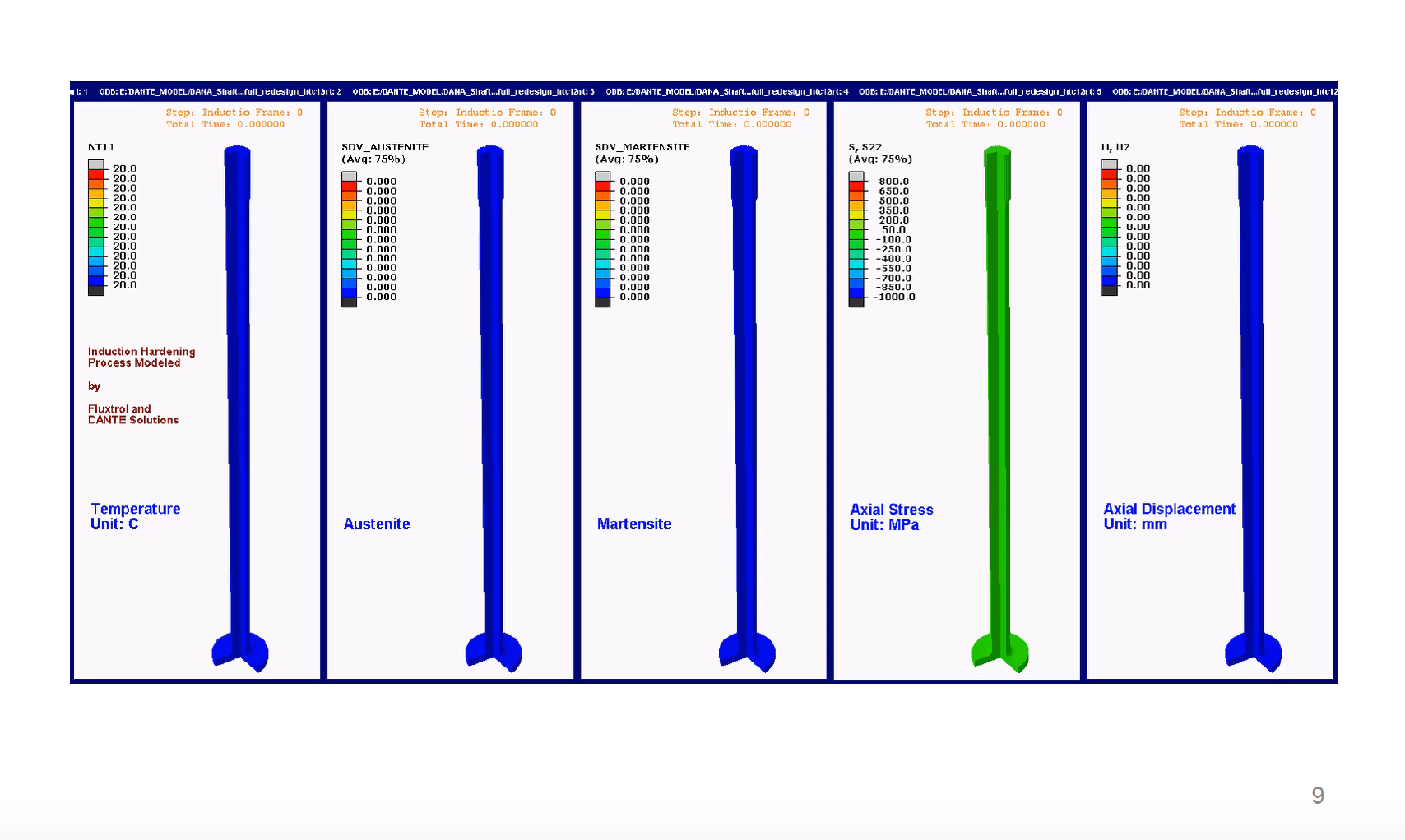
DANTE Simulation of Scanning Process
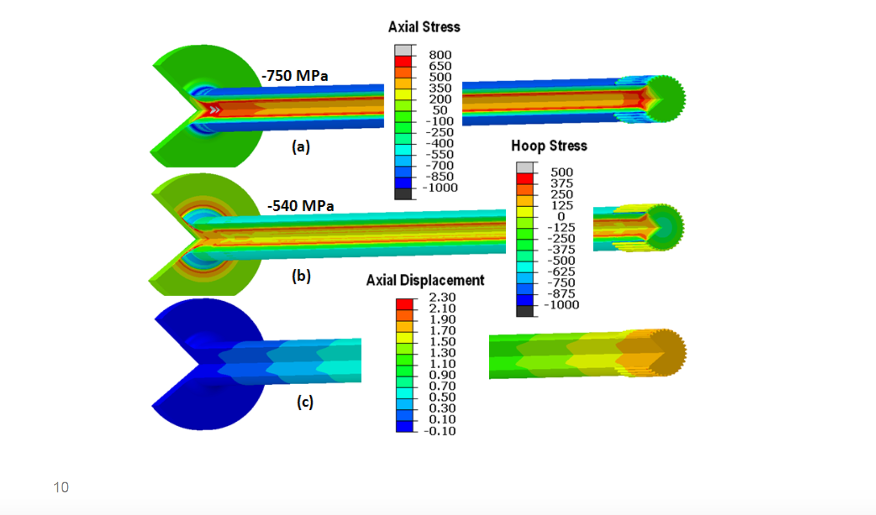
Stresses and Dimensional Movement after Hardening
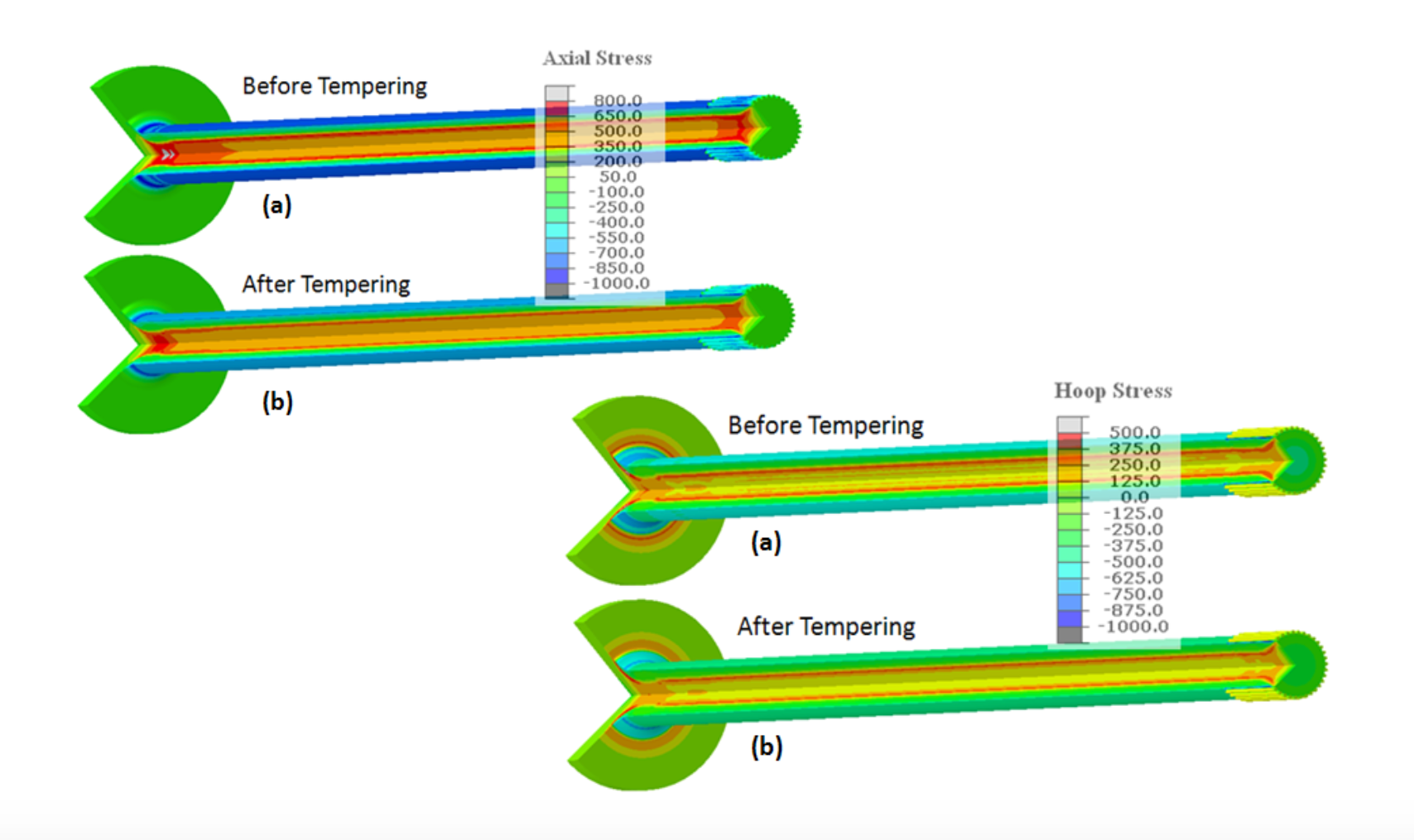
Effect of Tempering on Residual Stresses
Simulation of Torsional Loads
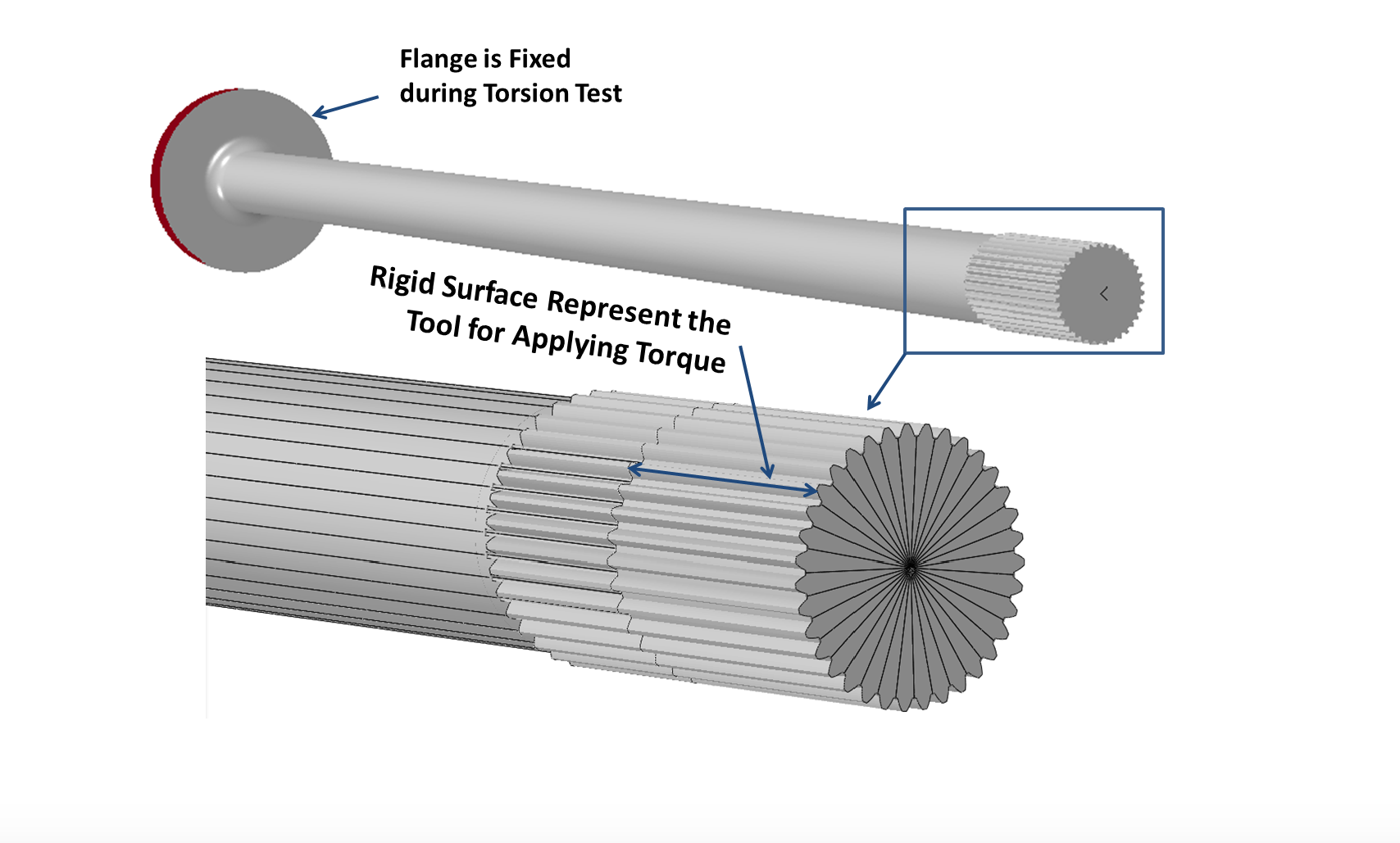
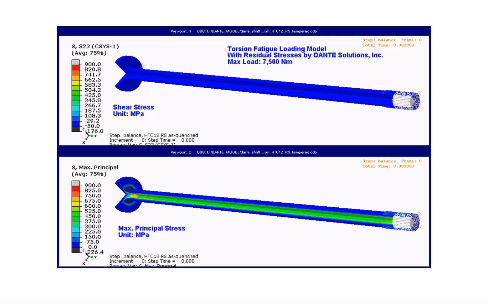
Dante Simulation of Torsional Loads
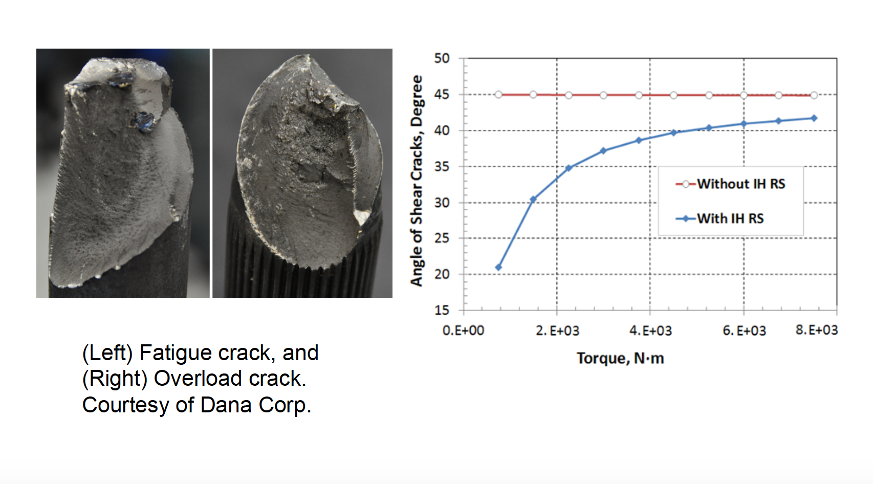
Failure Prediction
Conclusions
- Electromagnetic modeling by Flux and thermal-stress modeling by DANTE were successfully coupled
- High surface compression and high tensile stresses in core were predicted in model
- The largest tensile stresses occur at the base of the shaft and at the spline
- Total axial growth is 2.3 mm and radial shrinkage in shaft is 4μm. The authors have shown other papers that the axial growth and stress profiles are strongly influenced by the quenching severity.
- Virtual Loads were applied to the axle that simulate torsional testing equipment used in industry. Failure mode predictions are similar to what has been found while testing real components, showing that the residual stresses from the heat treating process have a strong influence on the component performance.
- Additional work needs to be done to incorporate residual stresses from manufacturing operations prior to the induction heat treating process to improve the accuracy of the predictions.
If you have more questions, require service or just need general information, we are here to help.
Our knowledgeable Customer Service team is available during business hours to answer your questions in regard to Fluxtrol product, pricing, ordering and other information. If you have technical questions about induction heating, material properties, our engineering and educational services, please contact our experts by phone, e-mail or mail.
Fluxtrol Inc.
1388 Atlantic Boulevard,
Auburn Hills, MI 48326
Telephone: +1-800-224-5522
Outside USA: 1-248-393-2000
FAX: +1-248-393-0277
Related Topics
- Applications of Induction Heating Enabling Advancement in Materials Science
- Effect of Steel Hardenability on Stress Formation in an Induction Hardened Axle Shaft
- Effect of Spray Quenching Rate on Distortion and Residual Stresses during Induction Hardening of a Full-Float Truck Axle
- Modeling Stress and Distortion of Full-Float Truck Axle During Induction Hardening Process