Information
Authors: V. Nemkov, R. Goldstein, J. Jackowski, N. Vyshinskaya, C. Yakey
Location/Venue: HES 10 Padua, Italy
Topic: Concentrator Heating
Abstract
Temperature control of magnetic controllers (concentrators, cores, shields, shunts) is an essential part of the induction coil design. Prediction and study of the coil copper have been described in a presentation “Influence of Cooling Conditions on Induction Coil Copper Temperatures” (V. Nemkov, R. Goldstein) [1]. That study was made using Flux 2D computer simulation program. The present study is devoted to temperature prediction and control in both copper and magnetic controller. Computer simulation with programs Flux 2D was used for modeling of the whole coil head operating conditions. Flux 2D has no standard option to account for magnetic losses in the concentrator material and their influence on the concentrator temperature. Special procedure has been developed to solve this problem. A case study illustrates the calculation procedure and influence of the coil head design, frequency, controller material selection and application technology on the controller temperature. New composite magnetic materials and temperature management methods are also described.
Introduction
Magnetic flux control, i.e. modification of magnetic field intensity and distribution may be accomplished by variation of the coil turn shape and positioning, by insertion of non-magnetic shields (Faraday rings) and magnetic flux controllers (concentrators, cores, impeders, shields). Magnetic flux controllers are made of laminations, ferrites and magnetic composites.
The use of magnetic controllers on induction coils can provide the following advantages:
- accurately control heat pattern resulting in better part quality
- improve the coil efficiency and power factor resulting in higher production or energy savings
- protect machine or part components from unintended heating
- better utilize power transferred to the part in local heating processes
- reduce current demand to the coil improving performance of the whole system.
In many applications controllers give more than one benefit. It is important to mention that the controller design, selection of material and application technique can strongly influence lifetime of heavy loaded induction coils.
Soft magnetic composites (SMC) are well established materials for magnetic flux control in multiple induction technologies especially at middle and high frequencies [2] with Fluxtrol and Ferrotron materials dominating on the market. Main advantages of these materials are:
- excellent machinability that allows the user to create controllers of different shape
- with different material grades it is possible to cover the whole range of frequencies used in induction technique, from line frequency 50/60 Hz to 13.56 MHz
- high enough temperature resistance (up to 300 C for short exposure time)
- high magnetic permeability (up to 120) that is sufficient for all induction applications.
Of course, using controllers requires special knowledge in application technique in order to prevent premature failure of the coil. The main failure modes of the heat treating coils are the copper cracking due to overheating in cyclic processes and the concentrator overheating.
These two effects are coupled and in general must be considered together. On one side, characteristics of magnetic controller can influence the temperature of hot spots of the coil copper profile [3]. It was shown that in cyclic operations good thermal contact of copper to the controller can reduce maximum temperature of the copper corners. On the other side, if copper temperature in areas in contact with controller is too high due to incorrect coil profile cooling, the concentrator can be prematurely destroyed by heat transferred from the coil, which locally heat the concentrator instead of cooling.
In general formulation of these coupled effects there are too many variables for overall analysis and main attention in this paper is paid to influence of the magnetic material properties (losses, thermal conductivity, anisotropy) on concentrator temperature. The coil copper is assumed to be well cooled.
Temperature Prediction
Computer simulation of induction systems is mainly devoted to modeling of electromagnetic and thermal fields in the workpiece. Much less attention is paid to temperature prediction in the inductor (coil head) consisting of copper conductors, magnetic controllers and some structural components (cooling and mechanical components, inserts etc.). For temperature calculation in the coil head an electromagnetic analysis must be made initially to determine the power densities that exist both in the copper and concentrator of the inductor. The power in the copper can be calculated through well known analytical relations or by using standard capabilities of computer simulation program such as Flux 2D. Thermal results can then be easily predicted in the copper winding by simulation based on the power densities and surface conditions including internal water cooling [1,3].
However there is no standard option in Flux 2D for calculating the power densities in the core. A method of estimating the power losses in the magnetic concentrator had to be developed in order to make thermal predictions. Calculating the flux density in the concentrator is a standard ability of the software. Based on material properties, the relationship of flux density and frequency to the power losses (magnetic losses) is known from experimental study. The power densities can then be calculated outside of program Flux 2D and inputted into the model for a thermal prediction.
This study case is a single-turn channel coil with Fluxtrol concentrator, Fig. 1. Such inductors are widely used for heating end of rods, fasteners, strip edges and so on.
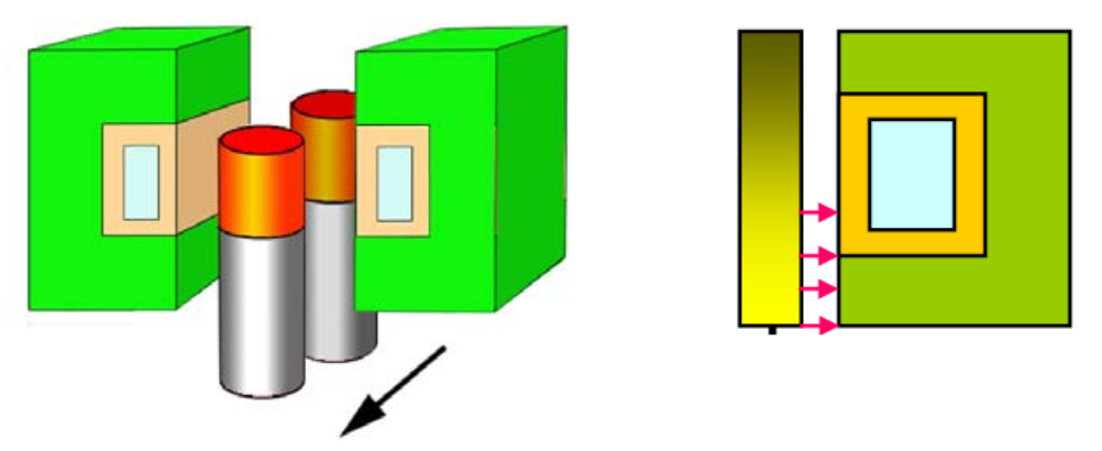
The volume of the core needs to be divided into regions with approximately constant values of flux density for a simplified evaluation of the power densities. A demonstration of this is in figure 2, displaying the sectioned regions of concentrator on the right, which corresponds to the overall distribution of flux density for a rough approximation. The distribution of flux density along with the field lines are shown on the left side of figure 2. One average value of flux density is assigned to each section of the core for calculating power losses if the material anisotropy is not taken into account.

Smaller flux density regions can be created if better discretization accuracy is desired, such as dividing the cross-section into small rectangular or triangle areas. Experience of calculations shows that even rough discretization provides good results due to strong averaging properties of the Fourier equation operator.
The power densities in each section of concentrator may be calculated from Eq. 1, and then inputted into Flux 2D for the thermal prediction.

Here a = 2-2.2 and b = 1-1.25 (see below).
Thermal boundary conditions must be applied to all the interfaces of the inductor. For example, the surface I1 of the concentrator (Fig. 2), is exposed to free air and an emissivity value for radiation and convective heat transfer coefficient are applied. Interface I2 has the same emissivity and convective coefficients, but since this is the inner surface of the coil, a certain amount of radiation from the part can be applied. Interface I3 has a heat transfer coefficient corresponding to the heat removal via cooling water. The layer of epoxy glue acts as a conductive thin body interface between the copper and concentrator. In this case a 0.5 mm thick layer of thermally conductive compound 50-3100 from company Epoxies, Etc. was used, which is the standard method of concentrator attachment for good contact with the copper (recommended gap is 0.2 – 0.5 mm).
All pressed SMC have certain anisotropy, i.e. different properties in direction of pressing (॥) and in perpendicular plane (ᅩ). Properties in perpendicular plane are much more favourable for induction heating. Material in favourable direction has better thermal conductivity, higher magnetic permeability and slightly lower magnetic losses. This fact may be effectively used for optimal material orientation in the concentrator. For example, concentrators made of Fluxtrol LRM have optimal magnetic orientation in 2D magnetic field [2]. The anisotropic thermal conductivity of the core can be inputted in simulation, as well as the thermal properties of all the materials included in the inductor assembly. To account for anisotropy it is necessary to define two components of flux density: one in favourable direction of heat transfer Bᅩ(perpendicular to material pressing direction) and one in direction of pressing - B॥. Power density equals to:

Here Pv is the volume power density, c1 and c2 are constants that vary with orientation, f is frequency. It is widely accepted that power density is proportional to frequency and B^2, i.e. coefficient a equals to 2 and b equals to 1. It is correct for low frequencies. For middle and especially for high frequency, losses grow with B and f faster than at low frequency and coefficients a can be as high as 2.2 and coefficient b can be 1.25. Therefore these coefficients must be carefully selected for good accuracy or losses defined directly from the curves and tables, not from the approximation expressions 1 or 2.
Simulation Results
This model allows us to study an influence of a variety of factors on the concentrator temperature such as its material properties, frequency, coil power, cooling conditions and environment. Some of the results are presented below.
Model dimensions: coil tubing – 25.4 x 12.7 x 2.5 mm, coil opening – 25.4 mm (Fig. 2), part – stainless steel plate 10 mm thick, coil and part length – 500 mm.
Operating conditions: frequencies 2 0 and 200 kHz, power in the part – 79 kW
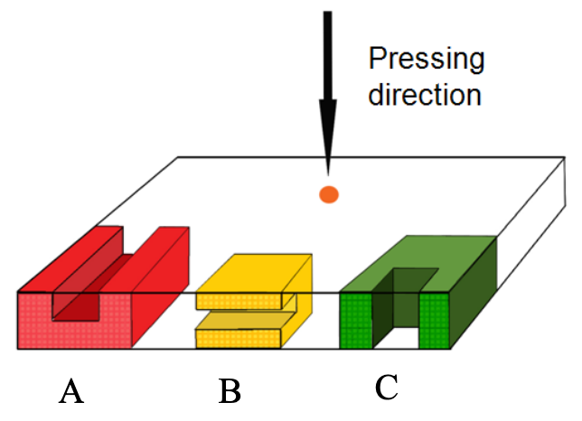
Concentrators: at 20 kHz – Fluxtrol LRM (optimal orientation C); at 200 kHz – Fluxtrol 50 with two orientations A and C (Fig. 3).
Electrical parameters of the inductor calculated by Flux 2D are presented in Table 1.
| Ptotal (kW) | Pcu (kW) | Pconc (kW) | Ppart (kW) | U (V) | I (A) | f (kHz) | Orientation |
|---|---|---|---|---|---|---|---|
| 104 | 23 | 1.7 | 79 | 183 | 4000 | 20 | C |
| 108 | 24.7 | 4.2 | 79 | 878 | 2190 | 200 | C |
| 109 | 25 | 5.8 | 79 | 877 | 2200 | 200 | A |
It follows from the table that for this case efficiency is almost the same for 20 kHz and 200 kHz. Losses in copper are slightly lower at low frequency in spite of much higher current than at 200 kHz. It is due to deeper current penetration in copper and more uniform current distribution along the coil tubing face. Magnetic losses in concentrator are much higher at high frequency, which is typical for induction heating in general. Optimal orientation of the concentrator material (case C) reduces losses about 28% compared to case A for the same material (Fluxtrol 50). However in all cases magnetic losses are much lower than losses in the coil copper.
Temperature distribution in the coil head is shown in Figure 4. Left picture shows gray-scale temperature distribution for the case of 20 kHz. Maximum concentrator temperature is 900C only. The central picture shows temperature in the coil with Fluxtrol 50 concentrator with non-optimal orientation (case A, Fig. 3). Here maximum temperature is close to 200 C, which is still tolerable for Fluxtrol material but close to upper limit (2500C). Concentrator temperature is much lower (Tmax = 1270C) when material has optimal orientation (right picture). It must be mentioned that temperature scale for the left picture is different than for two others in order to show temperature distribution pattern.
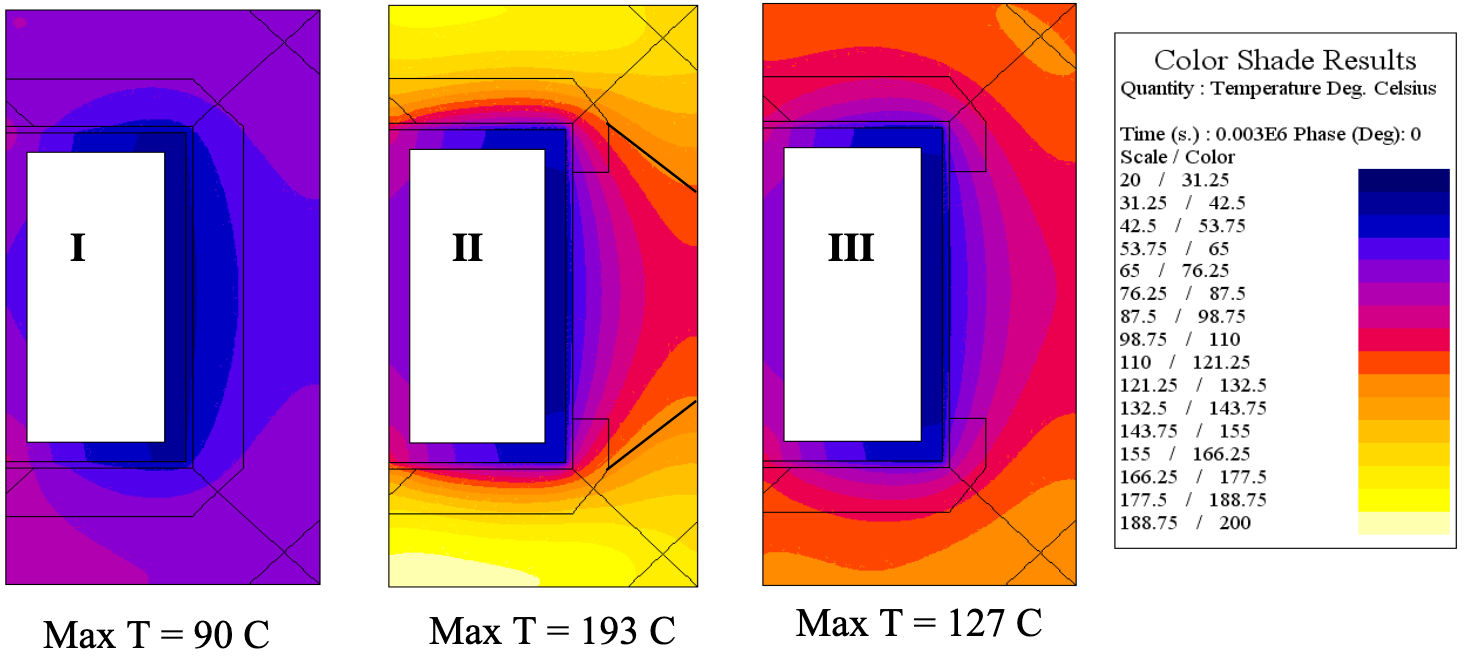
Results of Table 1 and Fig. 4 correspond to the beginning of the tunnel coil, i.e. at its entrance, where the part is still relatively cold. For this reason radiation from the part was not taken into account. Certain asymmetry of temperature field in the upper and lower poles is due to slightly different magnetic flux distribution caused by the part, see Fig. 2.
Thermal Management
Computer simulation reveals influence of various factors on the concentrator temperature. To control temperature many thermal management techniques were purposed and explored. The major methods are as follows:
- Optimal selection of the concentrator material and its orientation
- Design of the coil copper without hot spots in contact with concentrator
- Reduction of magnetic flux density by coil design, for example keeping minimum possible gap between the coil and part
- Selection of proper materials for adhesion and intermediate layers
- Additional cooling:
- external by attachment of cooling plates
- internal by means of channels for water cooling inside the material.
Optimal material selection. Two more materials were added recently to a family of traditional Fluxtrol and Ferrotron materials [3-5]. One material is Fluxtrol LRM manufactured in U-shape with optimal orientation of structure [4]. It may be effectively used instead of traditional lamination (Lamination Replacement Material) at low and middle frequencies.
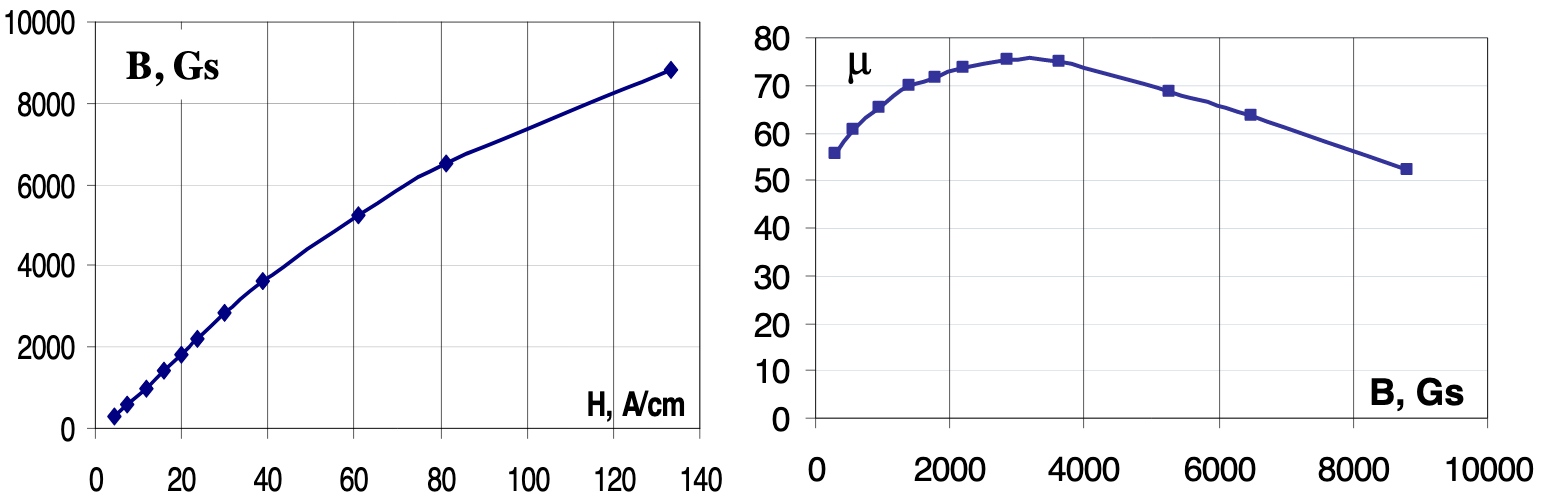
Another material is Fluxtrol 75 specially formulated for heavy loaded applications at middle and high frequencies (50-200 kHz). This material has high permeability (Fig. 5) and thermal conductivity, which allows effective temperature control when proper thermal management technique used. Material has excellent machinability as all other materials of Fluxtrol family. Example of its application is an inductor designed to create strong uniform magnetic field for biomedical research [5]. Another application is high magnetic flux guides in frequency welding (impeders and external controllers called Bridge, see below).
Design of the coil copper and interface with concentrator. Simulation revealed and practice confirmed that in many cases the magnetic controller starts to deteriorate not because of big magnetic losses but because of a local contact to hot copper mainly in the corners of the coil tubing where copper losses are high. This situation is especially critical when hardening inductors have no permanent cooling and their copper is cooled by quenching media after heating. The heat face of such inductors may reach temperatures of 350-400 C, which exceeds acceptable temperature of composite materials. The solutions are to introduce internal cooling of copper or thermally insulate concentrator from the copper in hot areas. In the second case the concentrator must be cooled by quenchant too.
Selection of glue layer. When the magnetic controller should be cooled by means of thermal contact to the coil copper or additional cooling plate, careful attention must be paid to selection of glue type and thickness. Thermally conductive epoxy compounds are the best material. In addition to high thermal conductivity glue must have sufficient temperature resistance to withstand maximum temperature of copper and good ductility to avoid separation from copper during the thermal cycling. Compound 50-3100 from company Epoxies, Etc is an example of such material. Glue must be thin enough to fill the gap but not too thin in order to prevent glue running out from the gap forming air pockets. Recommended gap for heavy loaded applications is 0.15-0.25 mm. Some customers use silicone glue due to more simple application. It is a good choice but only for low loading of concentrator because silicone glues have very low thermal conductivity.
Additional cooling is very effective especially for big magnetic concentrators. An example of application of additional cooling plate to the concentrator in the coil for generation of uniform magnetic field for biomedical research is described in [5].

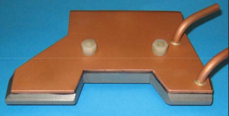
Internal cooling is relatively new method of thermal control. Figure 6 shows a water-cooled magnetic shunt for shielding of induction coil in vacuum furnace. In this application there are no convection losses from the controller and it is not easy to make reliable thermal contact to the coil. Shunt consists of two plates of Fluxtrol material. Channels for water cooling are milled on one plate, which is covered by another plate with an intermittent layer of epoxy glue. Plastic bolts hold assembly in the process of manufacturing and may be used for the shunt connection to the furnace structure. Inlet and outlet water connectors may be screwed into the plate with addition of epoxy glue for strength and water tightness.
Another example of internal cooling is Magnetic Bridges designed for improvement of high frequency tube welding (Fig. 7). Magnetic bridge [6] is an external magnetic controller, which provides improved path for magnetic flux around the coil from the welding V to upstream opening in the skelp. Calculations and experiments showed that magnetic bridge reduces Heat Affected Zone (HAZ), improves welding quality, reduces welding roll heating and reduces coil voltage, current and required power. Initial design of the bridge had a profiled plate of Fluxtrol material squeezed between two water-cooled copper plates.

In later design Magnetic plate has milled water channels covered by copper plate, which serves also as a device holder (Fig. 8).
There are more examples of thermal management technique. In many applications several temperature control methods may be used.
Conclusions
- Temperature prediction of magnetic controllers in a complex task, which requires consideration of electromagnetic and thermal phenomena and material characteristics. Computer simulation is the most accurate way to study and predict temperature distribution.
- When magnetic controllers are cooled by contact to the coil turns, coil temperature must be considered simultaneously with the concentrator. There are many cases when the concentrator fails due to too hot coil copper. Selection and application technique of a glue between the copper and concentrator plays a big role in temperature control.
- Selection of the concentrator material and its orientation can strongly influence the concentrator temperature and therefore the coil life time.
- There are many methods of the concentrator temperature control. One of them is an internal cooling of material by means of water channels milled inside the concentrator.
References
[1] Nemkov V., Goldstein R. (2007), Influence of Cooling Conditions on Induction Coil Copper Temperatures. Proc. Int. Symp. on Heating by EM Sources, Padua, 191-199
[2] www.fluxtrol.com
[3] Goldstein R., Nemkov V. (2007), Increasing Inductor Lifetime by Predicting Coil Copper Temperatures. Proc. ASM Int. Conference, Detroit
[4] Nemkov V., Ruffini R., Madeira R., Vyshinskaya N. Magnetic Flux Control in Induction Heat Treating. (2009). Proc. ASM Int. Conference, Indianapolis
[5] Nemkov V., Goldstein R., Ruffini R., Jackowski J., DeWeese T., Ivkov R. (2010), Design Study of Induction Coil for Generating Magnetic Field for Cancer Hyperthermia Research. Proc. Int. Symp. on Heating by EM Sources, Padua
[6] Nemkov V., Magnetic flux guide for continuous high frequency welding of closed profiles (2008). Intl. Patent Appl. No. PCT/US 2008/007390
If you have more questions, require service or just need general information, we are here to help.
Our knowledgeable Customer Service team is available during business hours to answer your questions in regard to Fluxtrol product, pricing, ordering and other information. If you have technical questions about induction heating, material properties, our engineering and educational services, please contact our experts by phone, e-mail or mail.
Fluxtrol Inc.
1388 Atlantic Boulevard,
Auburn Hills, MI 48326
Telephone: +1-800-224-5522
Outside USA: 1-248-393-2000
FAX: +1-248-393-0277