Information
Authors: Bulent Chavdar, Robert Goldstein, Lynn Ferguson
Location/Venue: IFHTSE 2016 Savannah, GA
Download Presentation PDF
Abstract
Feasibility of making lightweight powertrain products with hot hydroforging of steel/low density material hybrid billets is explored. A bimaterial billet is designed such that a steel wall encloses a low density core 100%. Furthermore the low density core is selected among the materials that have lower melting or softening temperature than steel such as aluminum and glass. In hot hydroforging the bimaterial billet is heated to 1000-1200 C range similar to the conventional hot forging of steel. However, in hot hydroforging the core is in liquid or viscous state while steel shell is in solid state similar to the conventional hydroforming. During hot hydroforging the viscous/liquid core has negligible resistance to flow thereby providing a uniform hydrostatic pressure inside the steel and enabling a uniform deformation of the solid steel wall.
Steel/aluminum bimetal billets were prepared. Then, the bimetal billets were hot hydroforged in closed dies in one blow. A uniform steel wall thickness was observed all around the forged part upon cross sectioning. However, there was also a large shrinkage void in the aluminum core. The large shrinkage void is formed due to the CTE mismatch between steel and aluminum and the volume increase of aluminum during phase change. The large shrinkage void can be eliminated if aluminum is replaced by glass that has a matching CTE to that of steel. Furthermore, glass does not have to be fully melted at forging temperatures thereby mitigating the risks of phase change. On the other hand the molten aluminum core can be emptied out of steel shell after forging thereby giving rise to the novel concept of "investment forging". A hollow part with uniform steel shell can be formed for the ultimate weight and cost reductions. For example investment forging of hollow steel valves for engine applications is feasible by hot hydroforging.
Introduction
Bimaterial products can be hot forged from a bimaterial billet where the steel wall encloses the lightweight core fully. A bimaterial forged product can be substantially lighter than a steel forged product. For example a bimaterial composite gear with 50/50 steel/glass composition by volume would reduce the weight of gear by about 35%. Weight reduction is one of the strategies to reduce the energy consumption and CO2 emission in motor vehicles. Every pound of weight reduction increases the energy efficiency of a midsized car by 0.01% [1]. Furthermore every pound of weight reduction reduces the CO2 emissions by 6 mg per 100 mile driving distance or by 20 pounds of CO2 for the life time of a vehicle [2].
A bimaterial billet can be forged in solid state however a better forging quality can be achieved if the core material is viscous thereby providing uniform hydrostatic pressure to steel wall during forging similar to a hydroforming process. However, the similarity only pertains to the hydrostatic pressure developed inside the deforming billet neither to the process temperatures nor to the method of providing the liquid phase. Hence, the forging of a bimaterial billet where the core material is in viscous or liquid state prior to the forging is named as “hydroforging”. Furthermore, if the metal outer wall is heated to temperatures greater than its recrystallization temperature while the core is in viscous or liquid state prior to forging then the hydroforging process is named as “hot hydroforging”. In other words, hot hydroforging can be defined as hot forging of lightweight products from a hybrid billet of a metal shell and a low melting core. For example, when a billet of a steel shell and glass core is hot hydroforged at temperatures higher than 1000C, the glass core is in a viscous state and the steel is in solid state above the recrystallization temperature.
Hydroforming is a well known process that uses a high pressure hydraulic fluid to press a working material into a die at room temperature [3,4]. While hydroforming is done at room temperatures the hot hydroforging is done at temperatures greater than 1000C enabling deformation of steel into intricate topologies with a streamlined forged microstructure without a fracture. Other differences between the hydroforming and hot hydroforging are that the amount of fluid is constant in hot hydroforging and the fluid may solidify and become an integral part of the product after forging and cooling unlike the case of hydroforming. The hydroforging process described in references [5] and [6] are very similar to the pressure assisted injection forging [7,8] and much different from the hot hydroforging technology described in this article. The lightweight core material will need to have a lower melting or softening temperature than the steel for hot hydroforging. Glass, aluminum and magnesium are such candidate lightweight materials. A literature search did not yield any prior study on the bimaterial billet forging where the core of billet is fully melted prior to the forging except our own paper in Reference [9]. Hence, we continue to discuss the industry first hot hydroforging process in this paper.
Our lightweight bimaterial gear concept includes a lightweight core material that is fully enclosed in a steel shell and formed into the teeth area thereby interlocking with the steel in the interior and contributing to the transfer of torque during the operation of gear. The formation of mechanical interlocking reduces the need for metallurgical bonding between the steel and the lightweight core. The concept gear has all around steel surfaces that engage with the mating gear at the outer diameter and the shaft at the inner diameter. It is envisioned that the steel frame would carry the bulk of torque from one component to the other and also would provide a long fatigue life to the gear. On the other hand the lightweight core would serve as a rigid-elastic continuum to transfer stresses inside the steel thereby providing toughness and reducing risk of plastic deformations to the steel shell under loading.
Behrens and Kosch describe a method of forging bimetal gears where steel does not enclose aluminum 100% and the torque transfer has to go through the steel, and the aluminum in a serial configuration, [11], [12]. Each component has to bear 100% of loads individually and they have to form a strong intermetallic bond. In our concept the loads are shared by the steel and the lightweight core. Furthermore, the torque is transferred from one component to the other mostly by mechanical interlocking. Furthermore, the mismatch of thermal expansion coefficients of steel and aluminum is always a big concern regardless of the forging method. A better material choice with a matching CTE is glass instead of aluminum. Glass and steel gear cannot be forged together by the method of Behrens and Kosch. On the other hand, steel/glass gears can be hot hydroforged together as demonstrated by modeling in this article. Another important distinction of hot hydroforging process is that it enables creating forged hollow products when the core is low melting metal such as aluminum or magnesium. The molten core can be emptied right after the final forging operation by piercing two holes one for draining the fluid and the other is for breaking the vacuum. Forged hollow products combine the benefits of streamlined microstructure with the maximum weight savings.
In Ref. [13] a C15 steel was cladded with 316L stainless steel and forged in solid state. Although the application did not have a lightweighting purpose it stressed the importance of friction condition at the die/billet interface that had a great impact on the final material distribution, forging loads and cracking occurrence. In Ref. [14] two semisolid alloys were mixed at micro level uniformly, then heated the bimaterial mixture between their liquidus and solidus temperature before forging. In the bimaterial hot hydroforging process two materials are not mixed. Hot hydroforging is also fundamentally different from the squeeze casting or liquid forging process where the molten material is poured into the bottom half of die and solidified under pressure [15]. In hot hydroforging the molten material is always contained within the solid steel shell of a billet and never contacts the die.
In this study the feasibility of hot hydroforging was investigated by modeling and also experimentation. Structural finite element analysis was conducted on ANSYS® software to determine the minimum steel wall thickness required to be able to transfer the same order of torque as in the case of all steel gear. Induction heating simulations of bimaterial billets were conducted on ELTA™ (1D) and FLUX™ (2D and 3D) software to establish a heating method with steel aluminum hybrid billets and presented in [9]. The induction heating method will be discussed further on a separate paper in this conference [10]. The stress state, dimensional changes and phase changes that occur during heating and cooling of bi-material billets were simulated using the DANTE® heat treatment software. The hot forging and the hydroforming simulations of steel-aluminum bimetal billets were conducted on the DEFORM® software. The steel/aluminum bimetal billets were prepared. A three piece closed die was designed and made for hot hydroforging experimentation. Hot forging in solid state and hot hydroforging experiments with liquid core were done on bimetal billets. The results were discussed and the future directions were identified.
Enabling Net Shape Gear Forging
Heavy duty manual transmissions require large size spur gears and helical gears made of carburizing steel. Most forged gears are made by two step manufacturing processes, hot forging followed by machining. First a tall cylindrical billet of steel is hot-forged to a flat shape in a series of busting and blocking operations and then a center hole and the teeth are formed by machining. Forty five percent of the starting material is wasted in the machining operations where the most waste is due to the teeth machining. The near net shape forged steel gears with light weight core can enable an 80% reduction in machining, thereby saving 2 to 4 kg waste per an average size gear. The raw material cost of a steel gear with light weight core may be significantly less than that of a gear produced from a solid steel billet because the volumetric cost of the light weight core can be lower than the cost of steel that is replaced. The reduction in waste also has a potential to reduce the carbon footprint of gear manufacturing operations. The objectives of hot hydroforging of gears can be summarized as follows:
- Lightweight gears with net teeth and near net center.
- The hybrid gear has all steel outer structure.
- Investment forging is enabled (molten core can be emptied).
- Press loads are reduced and larger gears can be forged.
- 30% to 50% weight reduction per gear can be achieved.
- Up to 10% weight reduction per transmission is expected.
- 60% to 70% reduction in machining scrap rate due to near net teeth is expected.
- Gear teeth can be through hardened and temperedin one-heat of forging.
- Alternatively, gear teeth can also be induction hardened after forging.
Hot hydroforging concept is an enabler for a near net forging of large gears with the teeth from lightweight bimaterial billets as discussed in [9]. Figure 1 shows the design of a bimaterial billet where the outer structure is made of 100% steel and the inner structure is 100% lightweight core. Figure 2 shows the assembly of the bimaterial billet by fitting the aluminum core in a steel tube and welding two steel endcaps to the steel tube. Figure 3 shows the concept of hot hydroforging a bimaterial gear in a two blow forging operation. In the first blow a flat shape is forged and in the second blow the teeth and the center hole are forged. From safety perspectives all blows are recommended to be done in closed dies. Since the core is in viscous or liquid state, the core can be squeezed out of center in the blocking operations. If the core is in solid state, it is not possible to squeeze out the material from the center. Squeezing the core material out of center and bringing the opposing steel walls in contact at the center will enable the containment of core within steel even after machining the steel center slug out. The resulting all steel walls at the inner diameter of the center hole will enable the assembly of hybrid gear on a steel shaft either by welding or by cutting splines on the steel wall and the steel shaft.
Structural Finite Element Analysis of Bimaterial Gear
Finite Element Analyses (FEA) were conducted to investigate the load carrying capacity of idealized lightweight gears prior to experimentation. The structural finite element analysis of bimaterial gear has the following objectives: determining the optimum steel wall thickness with alternative core materials, determining the size and load carrying capacity of gear and the deflections of bimaterial gear under load. Lightweight materials such as aluminum and glass have lower elastic modulus than steel does. When the core of a steel gear is replaced by a lightweight material it is expected that the deflections and the bending stresses on the steel casing of a composite tooth will be higher than those on an all steel tooth under the same load. It is clear that the thinner the steel casing is the higher the weight reduction. However, the stresses will also be higher when the steel casing is thinner. Hence, there is an optimum steel wall thickness where the weight reduction is high enough (>25%) to be attractive and the stress increase in the steel casing is either tolerable or manageable with minor design changes (‹10%).
A simple spur gear was selected as the basis for structural analysis. The gear has 24 teeth with a coarse pitch of 15.7 mm, outer and inner diameters of 129.0 mm and 68.8 mm and a width of 60.3 mm. Weight reduction, deformation and stress calculations were carried out for three different cases of steel wall thicknesses with an aluminum core. The weight reductions are 30%, 35% and 40% with the steel wall thicknesses of 3.5 mm, 2.5 mm, and 1.5 mm respectively. In these calculations it is assumed that the teeth are all steel and the outer diameter of aluminum core has a uniform distance of 3.5 mm, 2.5 mm, or 1.5 mm from the roots of teeth, from the outer side walls and from the ID of the gear for each thickness case as shown in Figure 4. The interface between the steel and the aluminum is assumed to be bonded. Although it is not considered in the current calculations, if the lightweight core had penetrated deep into the teeth area then additional 9% weight reduction could have been achieved for the case of 1.5 mm uniform steel wall thickness.
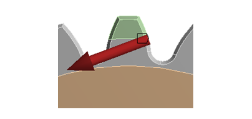
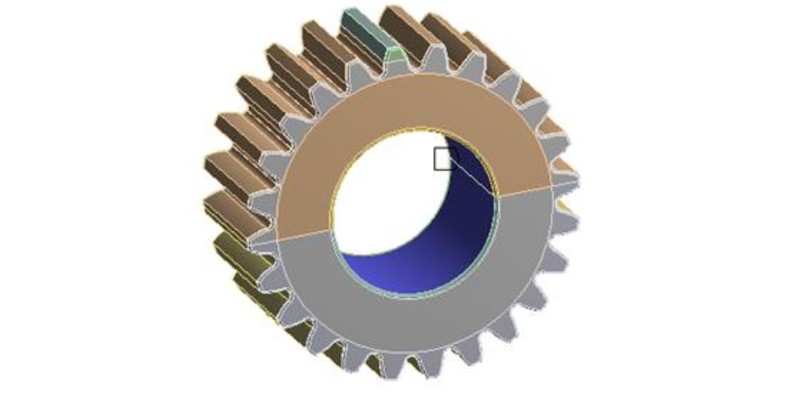
Finite element analysis was conducted to compare the stresses in the lightweight gears and the all steel gears. The 3D model of gear is created on Pro/Engineer® software and transferred to ANSYS® software. The gear is loaded on the pitch line of 119.8mm diameter with a point load of 24181 N normal to the tooth surface as shown in Figure 5. The tangential component of 22638 N creates 1356 Nm torque at the gear center and the radial component of 8500 N acts towards the gear center. For the boundary conditions, a fixed cylindrical support was applied on the surface of hole as shown in Figure 6. The whole gear model was meshed with Solid186 elements and analyzed. The number of elements is determined such that the mesh error was less than 5%. The maximum bending stress at the root of tooth is explored by smart meshing. Weight reduction and stress predictions are presented in Table 1 as function of steel wall thickness.
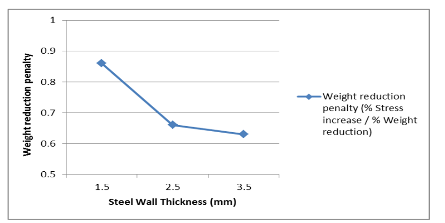
The maximum bending stress occurs at the root of a tooth. The von-Mises stress is 128 MPa for all steel gear. The von-Mises stress is 152 MPa, 158 MPa and 172 MPa for 3.5 mm, 2.5 mm and 1.5 mm steel wall thicknesses. Although the von Mises stress is higher with the bimetal gears than with all steel gear all of the calculated values are lower than yield and fatigue strengths of a typical structural steel. The ratio of percentage of stress increase to percentage of weight reduction is defined as the weight reduction penalty factor. The lowest penalty factor is provided by the 3.5 mm steel wall thickness (0.63). A. 2.5 mm steel wall thickness can also be considered as an aggressive weight reduction target with 0.66 penalty factor. However, 1.5 mm steel wall thickness should not be considered due to the increased penalty factor (0.86) as shown graphically in Figure 7.
| Steel wall Thickness (mm) | Weight reduction (%) | von-Mises stress (MPa) | Max Prin (MPa) | Min Prin (MPa) |
|---|---|---|---|---|
| All steel | 128 | 125 | -141 | |
| 1.5 | 40 | 172 | 165 | -193 |
| 2.5 | 35 | 158 | 149 | -171 |
| 3.5 | 30 | 152 | 139 | -165 |
First Hot Hydroforging Experiments of Steel-Aluminum Billet
The simulations and experimentation with the hot hydroforging of steel-aluminum bimetal billets were discussed in detail in [9]. The learnings are summarized here. Simulations showed that if the bimetal billets of steel and aluminum are forged in solid state then the steel wall thickness does not remain uniform during forging. Thinning, thickening, folding and cracking happen all at the same time at various locations on the deforming steel wall. Hence, it was necessary to have the core material melted prior to forging to achieve much more uniform steel wall thickness than the one attainable by solid state forging. The liquid phase inside steel provides a uniform hydrostatic pressure and no resistance to flow that enables the deformation of steel into intricate shapes with a uniform wall thickness as shown by hydroforming simulations in [9]. The uniformity of steel wall thickness is quantified with “non-uniformity index” that is the thickness ratio of the thickest wall to the thinnest wall in a forged bimetal product. A non-uniformity index of 1 means a perfectly uniform wall. It was shown by modeling that the hot hydroforging operation improves the steel wall non-uniformity index significantly as compared to the solid state forging by means of multi-blow indexed forging [9].
| Factors | Levels | |
|---|---|---|
| Wall thickness | 0.25" | 0.5" |
| Steel tube type | Seamless | With seam |
| Interference fit | 0.003" | 0.005" |
| Forging technique | Hot (solid state) | Hot hydroforging |
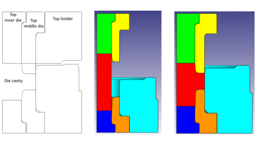
The predictions by modeling were verified by hot hydroforging experimentation with steel-aluminum bimetal billet. The end cap weld zones are identified as the high risk areas for structural failure prior to the experimentation. A closed die design was conceived as shown in Figure 8 in that the end zones of billets are confined in die pockets that prevent the deformation of heat affected zones during busting forging. In the experimentation phase the effects of initial steel wall thickness, the steel tube type, the interference fit as well as the forging technique on the forge-ability of bimetal billets were investigated. Table 2 shows the design of experiments and the levels of factors.
The most significant factor affecting the forge quality was the forging technique. Wall thickness and the steel tube type had no effect on the forge quality. Interference fit affected the induction heating phase in that the higher the interference fit is higher the chance of billet cracking during the heating phase prior to forging. Hence, it was concluded that interference fit is not needed in the bimetal billets.
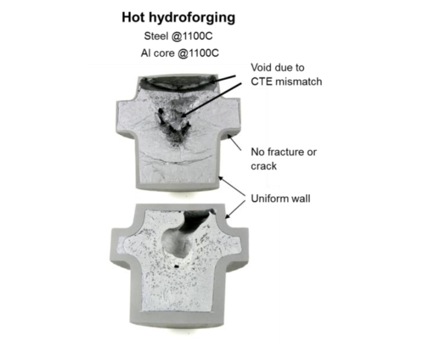
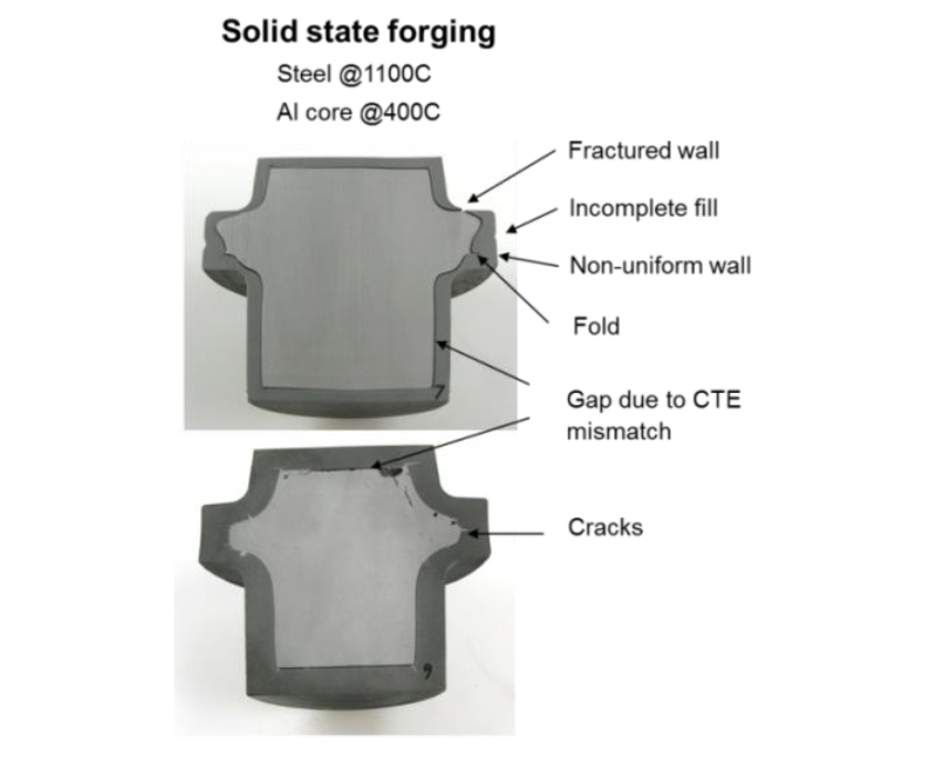
The steel wall thickness was much more uniform with hot hydroforging (Fig. 9) than the case of solid state forging (Fig. 10) overall. Both the billets with 0.25" and 0.5" steel wall thickness were forged successfully in that the steel wall thickness was uniform all around after the hot hydroforging as compared to solid state forging. While solid state forging exhibited folds, cracks and non-uniform deformation of steel wall, the hot hydroforging did not exhibit any folds or cracks and the steel wall thickness uniformity was much better. The steel wall thickness was thinned around the corner radius of the middle die but did not fracture with hot hydroforging as it did in solid state forging.
Large shrinkage voids formed in the aluminum core after hot hydroforging due to the CTE mismatch. Aluminum shrinks much more than steel does during cooling. Furthermore, the volume of aluminum contracts 6% when its phase changes from liquid to solid. These two effects contribute to the voids in the aluminum core. Since the voids in the core are not desirable a different material than aluminum needs to be selected as the core. Experiments with aluminum core were useful to demonstrate the steel wall thickness uniformity in hot hydroforging.
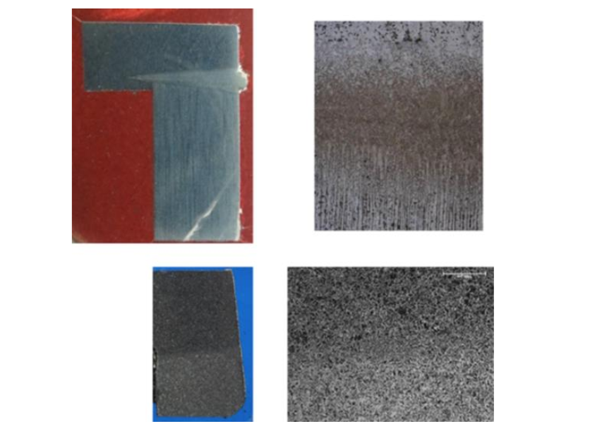
A significant healing of the microstructure of the weld zone was observed after the hot hydroforging. Figure 11 compares the microstructure of the weld zone of the electron beam welded steel end cap and the steel tube before and after the hot hydroforging. The dendritic directional grains of the weld bead and the coarse-grained heat affected zone transformed into a uniform normalized microstructure upon hot hydroforging [9].
Modeling Results ofHeating and Cooling Steel-Glass Billet
After demonstrating that a uniform steel wall thickness with uniform microstructure is achieved by hot hydroforging, our attention shifted to eliminating the large shrinkage void in the core. The large void in the core is caused by the mismatch of CTEs of steel (10 ppm) and aluminum (20 ppm) and 6% volume change in aluminum during the phase change. One idea to eliminate the void is to use a low density core material with a CTE that is similar to that of steel. Conventional soda lime glass was identified as a low density (2.5 gcc) core material with matching CTE (10 ppm). Furthermore, glass having amorphous structure neither have abrupt phase change nor abrupt volume expansion unlike aluminum upon heating and cooling. Induction heating and air cooling cycle of steel-glass bimaterial billet were discussed in [9]. It was shown that due to the faster rise of temperature in steel a gap forms between the steel and glass during heating, however, the gap closes upon cooling. An additional advantage of steel-glass billet could be the possibility of furnace heating or conventional low frequency induction heating due to the matching CTEs of steel and glass. In contrast it is necessary to use an expensive high frequency induction heating system to heat steel-aluminum bimetal billets to avoid billet cracking caused by the CTE mismatch as discussed in [9]. The feasibility of furnace heating and air cooling of steel-glass billet is investigated by modeling in the DANTE® heat treatment software in this paper. The model considers the three dimensional displacement of constituents as function of temperature and the allotropic phase changes in steel.
Steel-glass billet with 0.5” steel wall thickness is selected to model the stress-deformation behavior during furnace heating followed by air cooling. The initial microstructure of steel is assumed to be 50% ferrite and 50% pearlite. The objectives of modeling were to investigate the likelihood of billet cracking during furnace heating prior to forging and to predict any gap or void formation between steel and glass during air cooling after forging. It is assumed that glass completely fills steel cylinder at initial room temperature condition. Four sided elements are used for the finite element modeling of both steel and glass. Axisymmetry and vertical symmetry are assumed in order to reduce the computation time resulting in a quarter model. Steel cylinder is modeled with 25,120 elements and 25,563 nodes while glass core has 20,000 elements and 20,331 nodes. Contact surfaces are defined between glass and steel surfaces. Time temperature schedule is made of 1 hour heating at 1050C and 1 hour air cooling to 20C.
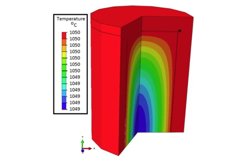
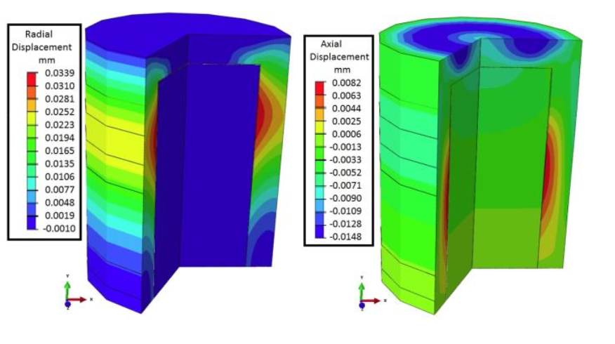
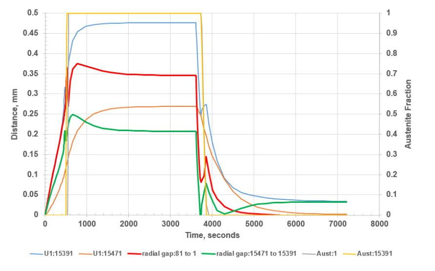
Uniform temperature is achieved in the bimaterial billet at the end of 1 hour heating as shown in Figure 12. The predicted radial and axial displacements are shown in Figure 13 for this cylindrical shape. A radial gap ranging from 1.8 µm to 32.5 µm is predicted, and an axial gap of about 2 µm is predicted. The time history of gap formation in radial direction at mid-height of the cylinder and at 30 mm from the top of glass are shown in Figure 14. The final radial gap is zero at mid-height of cylinder and 32.5 µm at 30 mm from the top of glass. These gap prediction assume no bonding between the steel and glass. A forged geometry should be investigated as it should behave differently than this simple cylinder.
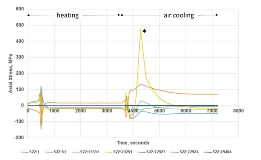
The steel node 20251 that is marked with an asterisk on Fig. 12 experiences 500 MPa tensile stress due to the volumetric expansion of the steel as the austenite transforms to ferrite and pearlite as shown in Figure 15. Glass may need to be chamfered at the corners in order not to resist the expansion of steel thereby reducing the axial stress. Otherwise, such high stress may compromise the integrity of bimaterial billet prior to forging.
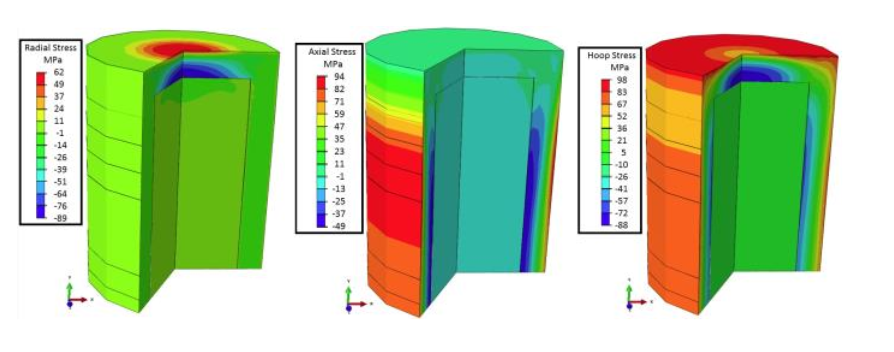
Final stress states after heating and air cooling are shown in Figure 16. The residual stresses in radial direction are near zero while there is compressive residual stress less than 10 MPa in the axial direction in glass. The compressive residual stress is beneficial for the fracture toughness of glass. The residual stresses are compressive on the inside and tensile on the outside of steel. All residual stresses, radial, axial and hoop are less than 100 MPa in magnitude therefore posing no threat of fracture in steel.
Showing the feasibility of furnace heating of bimaterial steel-glass billets is significant in that the bimaterial billets can be heated and forged by conventional methods without requiring new investment in high frequency induction heating.
Most gears need to be heat treated after forging in order to increase the strength, toughness and wear resistance. Since hot hydroforging of bimaterial gears can enable near net shape gear forging, the gear can be quenched immediately and cooled in air or furnace to get a through hardened steel wall with a relatively soft and elastic glass core. The heat capacity of glass core should be able to temper the steel after quenching. When it is carefully planned such heat treatment method can replace the expensive carburizing and nitriding heat treatments of gears that require additional steps.
Discussion
Lightweighting is an energy saving strategy for the transportation industry. Transmission and driveline components account for 5 -10% weight of a typical class 7/8 tractor. The gears account for 20% weight of a heavy duty manual transmission. Currently 100% of truck gears are made of steel. If the gears are forged from a bimaterial billet such as 50/50 steel/aluminum by volume than 33% weight reduction in gears is possible. This translates into 0.5% reduction in the weight of a truck and 0.2% improvement in the fuel efficiency.
The torque capacity of a gear can be increased by increasing the size of gear and also by forging instead of by machining. Small gears can be forged since their press loads are manageable. However, most big gears are made by machining instead of forging due to big forging press requirements. Hot hydroforging enables forging of large gears on the existing presses due to the reduced press loads.
Feasibility of making lightweight gears with hot hydroforging of steel/low density material hybrid billets is explored for powertrain applications. The functional requirements of gears are determined for transmission applications. An integrated computational engineering approach is followed to determine the theoretical weight reduction targets that meet functional requirements. Design and testing methods are developed to mitigate the risks. Our bimaterial gear concept has a steel wall on the outside and a lightweight core on the inside. The steel wall will carry most of the torque while the lightweight core serves as a rigid-elestic space holder and reduces the weight of gear. Two material options are identified for the low density, low melting core: aluminum and glass. Both materials are relatively low cost and readily available. Aluminum is a lightweight metal and second to the steel in terms of the availability and the cost. However there are many risks and challenges when aluminum and steel are used together in a structural product such as a gear. The biggest technical challenge is due to the difference in the coefficients of thermal expansion (CTE) of steel and aluminum. The CTE of aluminum is twice the CTE of steel. Furthermore, the volume of aluminum increases upon melting. These two factors contribute to the formation of shrinkage voids in the core upon cooling after a hot hydroforging. After conducting intensive digital prototyping efforts, the experimental studies were carried out to prove the concepts.
For the experimental phase, steel/aluminum bi-metal billets were prepared. Then, the bimetal billets were hot hydroforged into a so called "pancake" shape in closed dies in one blow. In hot hydroforging experiments the bimaterial billet was heated to 1000-1200 C range with a high frequency induction heater as guided by the induction heating modeling. Aluminum is allowed to melt inside the steel without fracturing the steel case by a cyclic on/off control of the power of heater. During hot hydroforging the liquid core flows effortlessly and provides a uniform hydrostatic pressure inside the steel thereby enabling a uniform deformation of the solid steel shell. Upon cross sectioning a hot hydroforged part, a uniform steel wall thickness was observed all around the part. However, there were also large voids in the aluminum core as expected. Using glass as the core material instead of aluminum will solve the void issue since glass has a matching CTE to steel. The benefits of matching thermal expansion behavior to eliminate shrinkage void had been demonstrated in [9] by deformation modelling of high frequency induction heating and air cooling of steel-glass bimaterial billets. In the present paper, the deformation studies are extended to the furnace heating and air cooling of steel-glass bimaterial billets. The results demonstrate that the bimaterial billets can be furnace heated before forging and air cooled after forging safely. A very small gap, less than 33 microns, is predicted between steel and glass at certain locations, however, these simulations assumed no adhesion between the steel and glass. In reality, glass and steel can form very strong adhesion and as result may not have any gap.
Heating the steel-glass billets to forging temperatures will be safer, simpler and faster than heating the steel-aluminum billets. It can be also envisioned that hot hydroforged steel-glass bimaterial gears can be quenched right after forging and be tempered by the latent heat of glass during the air cooling. The novel heat treatment procedure can save time and money by replacing the time consuming and costly carburizing and nitriding heat treatment procedures. Hence, the next series of hot hydroforging experimentation can be planned around the steel-glass material combination. Glass is 10% lighter than aluminum thereby providing further weight reduction benefits. These options need to be explored further.
On the other hand, aluminum core enables a novel concept of “investment forging” where the molten aluminum core can be emptied out of the part right after forging analogous to investment casting. A hollow part with uniform steel wall can be formed for ultimate weight savings. For example, investment forging of hollow steel valves for engine applications is feasible by hot hydroforging. In some cases the core can be emptied out later after creating evacuation holes at room temperature and reheating the part if it is difficult to empty the core right after forging. The hollow core can be filled with sodium to increase the heat transfer in exhaust valves as already been practiced today. Any low melting substance that does not go into gas phase at forging temperatures is a candidate as the core in investment forging. Core materials such as aluminum or magnesium that are extracted from the product during investment forging can be recycled.
The experimentation with hot hydroforging addressed several risk factors that had been identified and put into test. One of the concerns was if the degree of interference fit would have any impact on the quality of bimetal billet forging. The experiments indicated that an interference fit is not needed. Another concern was about the vulnerability of the weld seams to failure during forging. The experiments has shown that it is reasonable to expect that the weld zones of billet will heal and have no adverse effect on the performance of the end product upon hot hydroforging [9]. These guidelines lead to significant cost savings for the preparation of billets in a mass production scenario.
Conclusions
The feasibility of hot hydroforging technology to form lightweight structural components from steel-glass bimaterial billets are advanced further in this paper. It is shown by the furnace heating and air cooling simulations of steel-glass bimaterial billet that the huge shrinkage void that forms during the hot hydroforging of steel-aluminum bimetal billets will be mitigated by steel-glass bimaterial billets. Gross reduction or total elimination of shrinkage void is attributable to the matching CTEs of steel and glass. Furthermore, glass neither exhibit abrupt phase change nor abrupt volume increase in the range of forging temperatures. Volume increase upon melting is a huge problem with the aluminum core. Hence it is feasible to make net shape lightweight structural components by hot hydroforging of steel-glass billets. Such components will have 100% steel outer wall and 100% glass core. The continuous steel outer structure will bear the load while glass core will provide toughness due to its rigidity and lower elastic modulus than that of steel.
It is possible to make low cost hollow products by means of investment forging that is a special case of hot hydroforging technology. In investment forging the low melting core is emptied after hot hydroforging. Hollow products of steel, titanium, copper alloys etc. can be created by investment forging. The remaining metal shell will have the strength benefits of a forged microstructure. For example investment forging of hollow steel valves for engine applications is feasible by hot hydroforging and needs to be explored further.
Acknowledgments
This research was funded and conducted at the Corporate Research and Technology Group at Eaton in Southfield, MI. Billet induction heating simulations were provided by Fluxtrol Inc. in Auburn Hills, MI. The high frequency induction power supply was provided by Interpower Induction Services Inc. in Fraser, MI. Forging services were provided by Walker Forge Inc. in Clintonville, WI. Further billet heating, cooling and deformation modeling were provided by DANTE Solutions Inc. in Cleveland, OH. The authors would like to thank following team members for their contributions: Dr. Xi Yang, Mike Killian from Eaton, Jake Butkovich, Dr. Peter Fritz from Eaton.
References
[1] R. Heuss, N. Mueller, W. v. Sintern, A. Starke, A. Tschiesner, “Lightweight, heavy impact”, Advanced Industries, Feb. 2012, McKinsey & Company.
[2] “Impact of Vehicle Weight Reduction on Fuel Economy for Various Vehicle Architectures”, Research Report Conducted by Ricardo Inc. for The Aluminum Association, 2008-04.
[3] M. Ahmetoglu, T. Altan, “Tube Hydroforming: State-of-the-Art and Future Trends”, Journal of Materials Processing Technology, Vol. 98, pp 25-33, 2000.
[4] M. Koç, “Advances in Tube Hydroforming - An Enabling Technology for Low-Mass Vehicle Manufacturing-Material, Lubrication, Loading, Simulation Issues, and Alternatives”, Tsinghua Science and Technology, ISSN 1007-0214 04/18, Vol. 9, No 5, pp 527-545, Oct. 2004.
[5] M. Roeper, S. Reinsch, “HYDROFORGING: A New Manufacturing Technology for Forged Lightweight Products of Aluminum”, Proceedings of IMECE 2005, ASME International Mechanical Engineering Congress and Exposition, November 5-11, 2005, Orlando, Florida USA, IMECE2005-80424.
[6] B. Alzahrani, G. Ngaile, “Preliminary Investigation of the Process Capabilities of Hydroforging”, Materials, Vol. 9, No. 40; doi:10.3390/ma9010040, 2016.
[7] R. Balendra, Y. Qin, “Pressured-Assisted Injection Forging of Thick-Walled Tubes”, International Journal of Machine Tools and Manufacture, Vol. 35, No.11, pp 1481-1492, 1995.
[8] Y. Ma, Y. Qin, R. Balendra, “Forming of Hollow Gear-Shafts with Pressure-Assisted Injection Forging (PAIF)”, Journal of Materials Processing Technology, Vol. 167, No. 2, pp. 294-301, 2005.
[9] B. Chavdar, R. Goldstein, X. Yang, J. Butkovich, L. Ferguson, “Hot Hydroforging for Lightweighting”, IDE 2015; Bremen, Germany; Sep. 23-25, Vol. 5, pp. 117-128
[10] R. Goldstein, B. Chavdar, L. Ferguson, “Modeling of the Heating Sequences of Lightweight Steel/Aluminum Bimaterial Billets for Hot Forging and Hot Hydroforging”, 23rd IFHTSE Congress; Savannah, GA -USA; April 18-22, 2016.
[11] B. –A. Behrens, K. –G. Kosch, “Production of Strong Steel-Aluminum Composites by Formation of Intermetallic Phases in Compound Forging, Steel Research International”, Vol. 82, No. 11, 2011, pp. 1261–1265.
[12] B. –A. Behrens, K. –G. Kosch, “Development of the Heating and Forming Strategy in Compound Forging of Hybrid Steel-Aluminum Parts”, Materialwissenschaft und Werkstofftechnik Vol. 42, No. 11, (2011), pp. 973-978.
[13] Jincai W, Langlois, L., Rafiq, M., Bigot, R., Hao, L. “Experimental &Numerical Study of the Hot Upsetting of Weld Cladded Billets”, Key Engineering Materials, Vol. 554-557, No. 1, (2013), pp. 287-299.
[14] Yang, Z., Dong, J., Zhou, L., Shen, L., Zhang, W. “A Study of the method of Manufacturing Bimaterial Composite Parts Through Semisolid Metal Processing”, Metallurgical and Materials Transactions A: Physical Metallurgy and Materials Science, Vol. 42, No. 6, (2011), pp. 1709-1716.
[15] ASM Handbook, Vol. 15-Casting, (2010), p. 1153..
If you have more questions, require service or just need general information, we are here to help.
Our knowledgeable Customer Service team is available during business hours to answer your questions in regard to Fluxtrol product, pricing, ordering and other information. If you have technical questions about induction heating, material properties, our engineering and educational services, please contact our experts by phone, e-mail or mail.
Fluxtrol Inc.
1388 Atlantic Boulevard,
Auburn Hills, MI 48326
Telephone: +1-800-224-5522
Outside USA: 1-248-393-2000
FAX: +1-248-393-0277
Related Topics
- Hot Hydroforging for Lightweighting
- Modeling of the Heating Sequences of Lightweight Steel/Aluminum Bimaterial Billets for Hot Forging and Hot Hydroforging
- Stress and Distortion Evolution during Induction Case Hardening of Tube
- Effect of Spray Quenching Rate on Distortion and Residual Stresses during Induction Hardening of a Full-Float Truck Axle