Information
Authors: Robert Goldstein, Bulent Chavdar, Lynn Ferguson
Location/Venue: IFHTSE 2016 Savannah, GA
Abstract
Recently, a concept to produce lightweight products by hot forging a steel shell that had a lightweight core was presented that could lead to component weight savings up to 50%. Some targeted products are gears, valves, and flanges. The steel shell is envisioned to carry most of the load in a target application while the lightweight core serves as a space holder during the forming process. After forming, the lightweight material may either remain in the component and contribute to the load carrying capacity, or be emptied out to achieve the ultimate weight reduction.
In this paper, the concept studied is hot forged from a bimetal billet, which is a steel tube press fit with a solid aluminum core and welded shut with steel end caps. For the experimental part of the studies Al 7075 was selected as the core material due to its high strength to weight ratio and 1020 steel was selected because of its availability as a tube. Induction heating was selected as the heating method for bimetal forging. This is due to the ability of induction heating to rapidly heat the steel layer. Successful bimetal forging of a closed vessel requires the steel layer to be in the austenite phase prior to the aluminum reaching high temperatures to prevent compromising the weld seams. Modeling of the induction heating process is complex due to the dimensional movement of components during the process. A method was developed to accurately model the induction heating process and predict power requirements. The method will be described and the results of the models will be compared to experimental findings. The forming process will be discussed in another paper at the conference. The simulation presented is for solid state forging of a steel aluminum billet, but the method for modeling the process is the same for hot hydroforging or other material combinations.
Introduction
Vehicular manufacturers and their suppliers are constantly being challenged to improve fuel efficiency, without sacrificing performance or increasing the cost. One of the ways to achieve fuel efficiency improvements is to reduce the weight of components. Removing material from non-load bearing areas, changing materials and changing heat treatment specifications are common methods being employed in the field to try to achieve these goals. Oftentimes, seemingly minor changes can lead to major complications to the manufacturing process, leading to a substantial increase in the component cost for a relatively minor weight reduction.
Bimaterial products are of interest to manufacturers, because they have the potential to offer significantly higher strength to weight ratios than components made of only one material. The challenge is how to produce them economically. One concept being explored is to produce bimaterial products using a hot forging process. Theoretical studies using computer simulation and experimental trials have been conducted to develop a process for manufacturing bimaterial gears using hot forging or a combination of hot forging plus machining. The bimaterial billets in this work consist of a lightweight core fully enclosed within a steel shell.
A bimaterial billet can be forged in the solid state, however better forging quality can be achieved if the core material is allowed to melt or flow, thereby providing uniform hydrostatic pressure to the steel shell during forging similar to a hydroforming process. However, the similarity only pertains to the hydrostatic pressure developed inside the deforming billet, not to the process temperatures. While hydroforming is done at room temperature, the hot hydroforging is done at temperatures greater than 1000C, enabling deformation of steel into intricate topologies without a fracture. Other differences between hydroforming and hot hydroforging are that the volume of fluid is constant in hot hydroforging and the fluid solidifies and becomes an integral part of the product after forging and cooling. The lightweight core material will need to have a lower melting or softening temperature than the steel for hot hydroforging. Aluminum, magnesium, and glass are such candidate lightweight materials [1].
Our lightweight bimaterial gear concept includes a lightweight core material that is fully enclosed in a steel shell and formed into the teeth area thereby interlocking with the steel in the interior and contributing to the transfer of torque during the operation of gear. The formation of mechanical interlocking is complementary to a strong metallurgical bond needed between the steel and the lightweight core. The exposed surfaces of the concept gear are all steel surfaces that engage with the other components of a transmission system, such as the mating gear(s) at the outer diameter and a shaft at the inner diameter. It is envisioned that the steel frame of the bimaterial gear would carry the bulk of torque from one component to the other and also would provide a long fatigue life to the gear. Furthermore, steel surfaces could be induction hardened to withstand very high Hertzian contact stresses between the mating components. On the other hand, the lightweight core would serve as a continuum to transfer stresses inside the steel shell, thereby providing rigidity and reducing risk of plastic deformation of the steel shell under loading. A comparison of this concept to other competitive bimaterial components is contained in the following papers [1, 2].
In this study the feasibility of hot forging and hot hydroforging was investigated by modeling and also experimentation. Induction heating simulations of bimaterial billets were conducted using ELTA™ and Flux™ 2D software. The hot forging and the hot hydroforging simulations of bimaterial billets were conducted initially in simplified models using DEFORM® and later in more complete models using DANTE® software. The steel/aluminum bimaterial billets were designed and prepared. A three piece closed die was designed and made for hot hydroforging experimentation. Hot forging and hot hydroforging experiments were done on bimaterial billets.
The goal of this paper is to present a method of modeling the heating process. The proper thermal, metallurgical and dimensional results are necessary in order to correctly design the forming process. The forming process and results are discussed and the future directions are identified and presented more in depth in another paper at this conference [2].
Bimaterial Gear Concept
Heavy duty manual transmissions require large size spur gears and helical gears made of carburizing steel. Most forged gears are made by two step manufacturing processes, hot forging followed by machining. First a tall cylindrical billet of steel is hot-forged to a flat pancake shape and then a center hole and the teeth are formed by machining. Forty five percent of the starting material is wasted in the machining operations where the most waste is due to the teeth machining. The near net shape forged steel gears with light weight core can enable an 80% reduction in scrap, thereby saving 2 to 4 kg waste per an average size gear. The raw material cost of a steel gear with light weight core may be significantly less than that of a gear produced from a solid steel billet because the volumetric cost of the light weight core can be lower than the cost of steel that is replaced. The reduction in scrap also has a potential to reduce the carbon foot print of gear manufacturing operations.
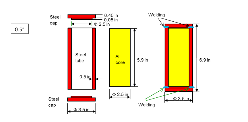
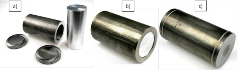
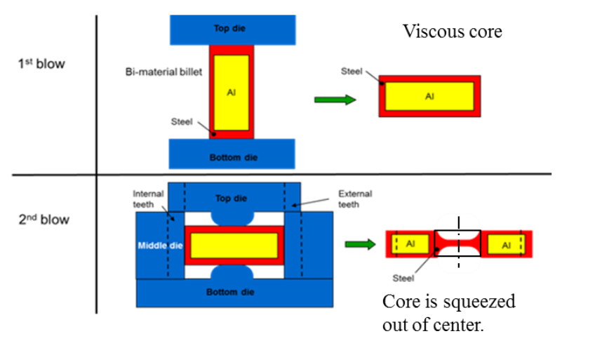
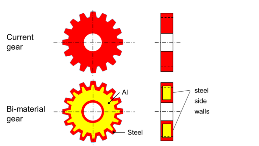
Hot forging and hydroforging concepts are an enabler for near net forging of large gears with the teeth from lightweight bimaterial billets. Figure 1 shows the components of the bimaterial billet design. Figure 2 shows the assembly of the bimaterial billet by fitting the aluminum core in the steel tube and welding the two steel endcaps to the steel tube. Figure 3 shows the initial concept of hot hydroforging a bimaterial gear in a two blow forging operation. Figure 4 shows the concept of bimaterial gear where the outer structure is made of 100% steel and the inner structure is 100% lightweight core. A more detailed description of the manufacturing process is contained in another paper at this conference [2].
Initial heating trials were conducted in a furnace for the steel-aluminum billets. With the slow, uniform heating process, the welds holding the caps on the die fractured during the heating process due to the thermal expansion of the aluminum core during the heating process (Figure 5).
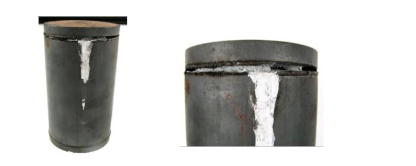
In order to prevent the cracking of the bimetal billet, the steel wall needs to be heated and expanded away from the aluminum core before aluminum is heated. The steel needs to reach above recrystallization temperatures before aluminum expands and catches up with the steel wall to prevent any cracking in the steel. When the steel is well above the recrystallization temperature even if aluminum catches up with the steel and exerts pressure on the steel it does not cause a problem since then steel can deform outwards easily to accommodate the expansion of aluminum without any fracturing. Based upon this concept, induction heating was explored.
Modeling of the Heating Process
For safety reasons, initially the hot forging concept was pursued. The goals for the induction heating modeling were to determine if it was possible to heat the steel casing and then to maintain a temperature at the mid-radius of greater than or equal to 750 C in the steel billet for a period of 10 s (transportation time from induction heater to forging press) without melting the aluminum core (Temperature below 600 C). The upper limit on surface temperature of the steel was set to 1350 C. The billet OD was 88.9 mm (3.5 inch). The wall thickness of the steel was 12.7 mm (0.5 inch). The radial gap and the top gap between the aluminum core and the steel shell was 0.076 mm (0.003 inch).
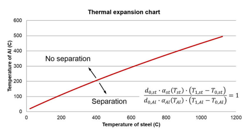
One of the big unknowns for the induction heating simulation is the thermal contact between the steel casing and the aluminum billet during the process. If the steel casing is heated substantially faster than the aluminum, a gap should grow between the steel and the aluminum bodies. If there is a gap, then heat transfer from the steel to the aluminum will move from conduction to radiation, resulting in much slower heating of the aluminum core. Calculations were made for the temperature of steel and aluminum that would result in the same thermal expansion (Figure 6). If the aluminum temperature is above the red line at a corresponding steel temperature, then the aluminum will be pressing up against the steel. If the aluminum temperature is below the red line at a given steel temperature, then the two bodies will be separated.
Preliminary computer models were made using ELTA™ software for a straight bimaterial tube of the same dimensions comparing the two threshold conditions –ideal physical contact and no physical contact. It was found that with ideal physical (thermal) contact, it was highly questionable even with a surface temperature of 1350 C if it would be possible to maintain the necessary temperature in the steel shell (750 C) without melting the aluminum core (600 C) through the transportation phase (5-10 s). Figure 7 shows the temperature results for the ½” steel wall billet with the induction equipment available (up to 600 kW at 10 kHz) for the tests (Figure 7). For the ¼” billet, the process did not appear to be feasible with the ideal thermal contact assumption.
With no physical contact between the components, the results looked much more promising. Even with no physical contact between the components, there would still be heat transfer between components by radiation and convection. To simulate the heat transfer, a thin layer with very low thermal conductivity was used. Under this scenario, the ¼” billet was more difficult to maintain temperature in the steel compared to the ½” billet due to the higher surface area to mass ratio. Figure 8 shows the temperature distribution for a ¼” billet with no physical contact between components. It is clear that even with a 1200 C maximum temperature, the process appears feasible.
Based upon the promising results from the ELTA™ software, more complicated, multi-software 2D modeling was conducted. 2D coupled electromagnetic plus thermal modeling of the process was done using Flux2D to develop a thermal cycle with the assumption of physical contact on the top and bottom surface of the billet. The power density distribution was then mapped and exported to Microsoft Excel. These results were then inputted into the DANTE® software for thermal, metallurgical, stress and dimensional movement models to validate the proposed cycle. If thermal contact was not as expected, Fluxtrol would then update the thermal cycle to achieve the desired results and the revised models would be sent to the DANTE® software. This procedure has been used successfully for induction heat treating of tubes [3] and axle shafts [4].
At this point, it was determined that a 500 kW, 10 kHz induction heating power supply from Interpower Induction (www.interpowerinduction.com) would be used for the tests. One of the limitations of this unit was that it was only possible to utilize two stages of power in a given cycle. A number of different potential cycles were developed for both the ¼” billet and ½” billets using 2D modeling. Only one selected cycle for the ½” 2D billet heating results is shown in this paper to demonstrate the concept.
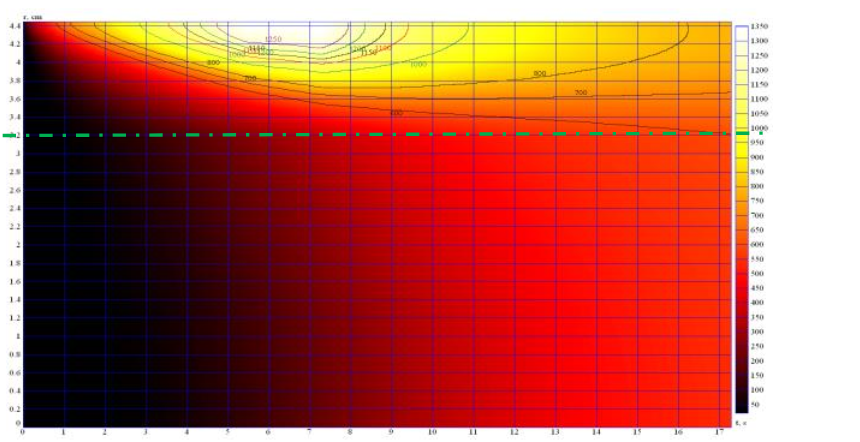
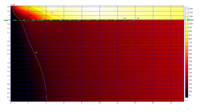
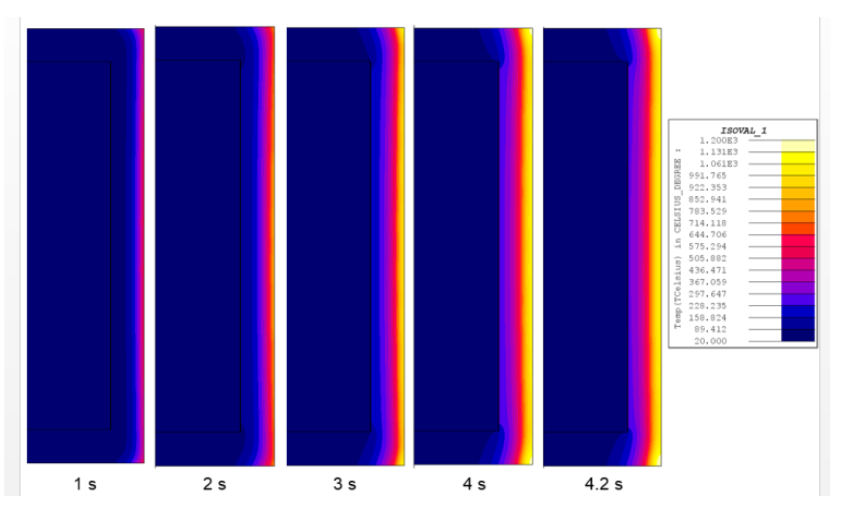
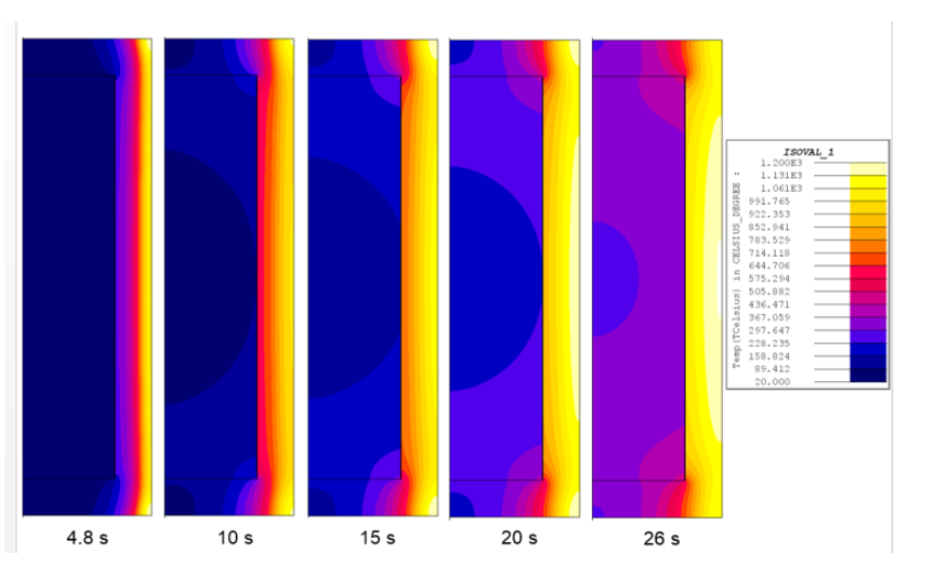
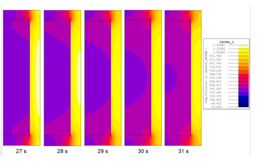
For this proposed cycle, the goal was to get the core as soft as possible without melting to prevent rapid quenching of the steel shell (and resulting tensile stresses) during the forming process where physical contact would occur between the steel and aluminum. Based upon these criteria, a 26 second heating cycle was developed. The cycle was designed such that the first stage would use high power (90%) for 4.2s to rapidly heat the surface up to the maximum temperature and ensure that the steel shell separated from the aluminum core (Figure 9). After this initial, high power stage, a much lower power level (20–25%) would be used for the second stage (21.8s) while the temperature equalized in the thickness of the steel shell (Figure 10). After heating, a 5 second transportation stage without power was modeled (Figure 11).
Due to the relatively short process and lack of thermal contact with the aluminum, there is a large temperature gradient between the hot, outer diameter of the billet and the center of the top and bottom steel caps due to the comparatively poor thermal conductivity of steel. If outer walls were to be in intimate contact with the aluminum (which would be molten at these temperature), the entire outer surface temperature would be close to uniform due to the much higher thermal diffusivity of aluminum.
The power densities at the different time steps were then exported into the DANTE® model. One difference between the Flux2D model and the DANTE® model was in the physical contact between the aluminum and the steel. In the DANTE® model, physical contact was assumed only for the bottom surface. This is the more appropriate assumption as it was expected that the steel will grow both axially and radially during the heating process.
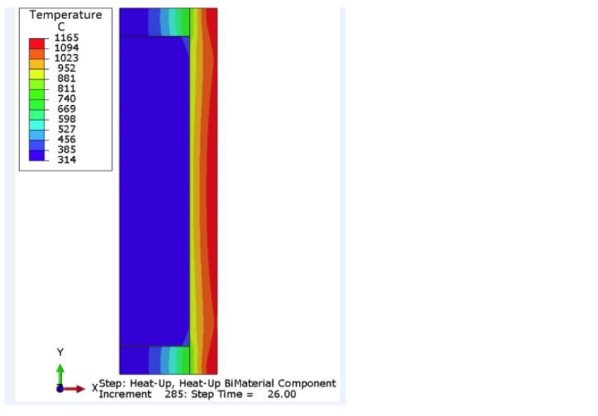
The temperature distribution at the end of the heating cycle in the DANTE® models is shown in Figure 12. The temperature distribution is similar to the one from Flux 2D, but the magnitude of temperature in DANTE® model is slightly lower. This is due to differences in the surface heat transfer coefficients (convective and emissive) used in the respective models. This could be resolved by adjusting the thermal boundary conditions. The aluminum core temperatures are quite similar (the lower start point on the temperature scale makes the DANTE® software model aluminum core appear cooler).
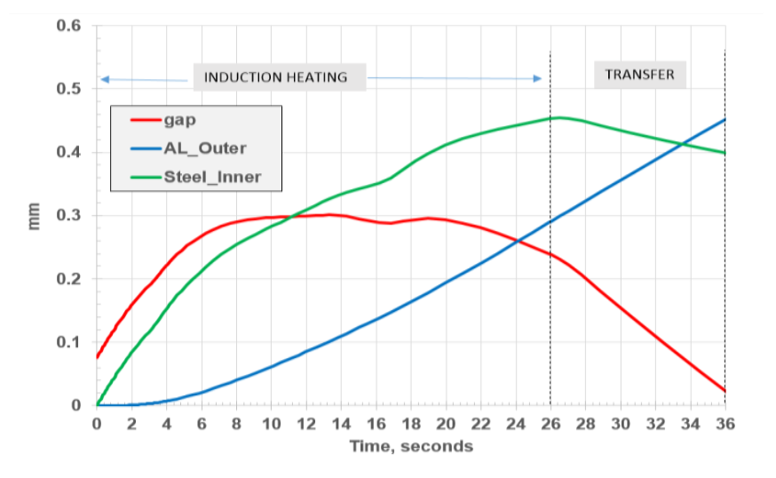
Figure 13 shows the radial dimensional movement for the steel ID and aluminum OD that occurs during the process. It is clear that at the very beginning of the heating process, the steel grows rapidly and the gap between the steel and the aluminum widens. In the middle of the process, the gap is nearly constant as the steel and aluminum grow at similar rates. Near the end of the heating process the gap begins to decline as the steel expansion slows and the aluminum continues to grow. During the transportation phase, the steel contracts as it cools, while the aluminum continues to grow as it is still being heated by radiation from the hot steel.
Experimental Validation of the Heating Process
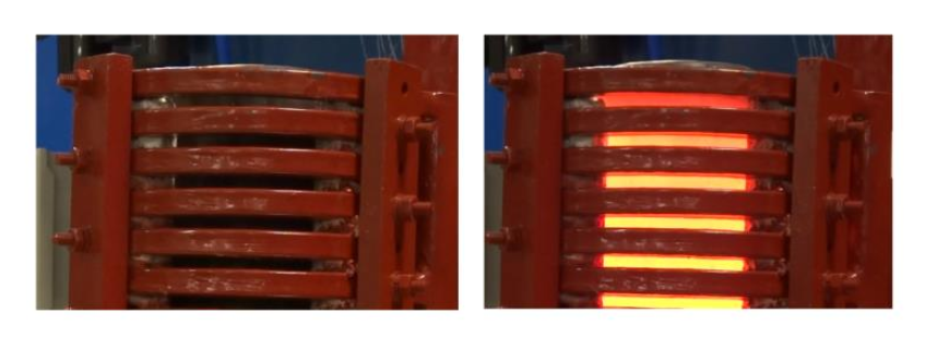
To verify the concept, it was decided to test a billet with a small hole drilled in the top of a ¼” wall billet to monitor the temperature of the aluminum in the Interpower lab. The tests were monitored using a camera mounted on a tripod. Figure 14 shows the billet before and a few seconds after a 4 second heat pulse at 400-500 kW, 10 kHz. It is clear that the billet maintains temperature in the center of the OD and also that the billet has grown by several millimeters. This much energy inputted into the billet would be insufficient to maintain this temperature if the billet were in good thermal contact with the aluminum core. In addition, further evidence of the cold core is that the upper and lower surfaces had much lower temperatures.
Initial heating trial results showed agreement with the models, verifying that with the proposed thermal cycle there would be separation of the materials. Based upon this, industrial tests were planned. The 500 kW, 10 kHz generator was moved from Interpower to Walker Forge for the forging tests. The forging installation at walker forge had a lift to remove the billet from the coil and a robot to transport the billet from the heating coil to the forging die. It was estimated that this process would take approximately 10 seconds.
A series of trials were performed building sequential up to the desired cycle. A two stage heating cycle 6 seconds high power (90% was programmed into the machine, but power dropped somewhat as the Curie point was reached), 20 seconds 20% According to the pyrometer on the machine, the temperature in the center of the billet at the end of the heating cycle was approximately 1250 C, very close to the calculated temperature. The temperature in the billet 2 seconds after the end of heating as the part is being lifted out of the coil is shown in Figure 15. It is clear that on the outer surface of the billet, temperature is relatively uniform. Due to the high temperature, it was difficult to get the camera to focus to discern the exact distribution. This also agrees quite well with models (Figures 10-12).
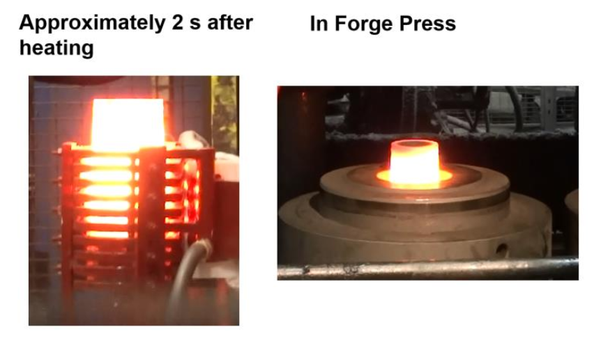
As the billet is placed in the die, the surface temperature of the billet has declined, but it remains high. In the image, it can be clearly seen that the top cap of the billet is substantially cooler than the sides. This also agrees well with the models and offers further proof that the aluminum core is not in contact with the steel shell.
Discussions
Lightweighting is an energy saving strategy for the transportation industry. Transmission and driveline components account for 5-10% weight of a typical class 7/8 tractor. The gears account for 20% weight of a heavy duty manual transmission. Currently 100% of truck gears are made of steel. If the gears are forged from a bimaterial billet such as 50/50 steel/aluminum by volume than 33% weight reduction in gears is possible. This translates into 0.5% reduction in the weight of a truck and 0.2% improvement in the fuel efficiency.
The torque capacity of a gear can be increased by increasing the size of gear and also by forging instead of by machining. Small gears can be forged since their press loads are manageable. However, most big gears are made by machining instead of forging due to forging press tonnage requirements. Hot hydroforging enables forging of large gears on the existing presses due to the reduced press loads. Feasibility of making lightweight gears with hot hydroforging of steel/low density material hybrid billets for powertrain applications is discussed in detail in another paper at this conference [2].
Our bimaterial gear concept has a steel shell on the outside and a lightweight core on the inside. The steel shell will carry most of the torque while the lightweight core serves as a space holder and reduces the weight of gear. Two material options are identified for the low density, readily formable core at temperatures equal to or below the forging temperature of steel: aluminum and glass. Both materials are relatively low cost and readily available.
For the initial trials, steel/aluminum bi-metal billets were studied. Aluminum is a lightweight metal and second to the steel in terms of the availability and the cost. However there are many risks and challenges when aluminum and steel are used together in a structural product such as a gear. The biggest technical challenge is due to the difference in the coefficients of thermal expansion (CTE) of steel and aluminum. The CTE of aluminum is approximately twice the CTE of steel. Furthermore, the volume of aluminum increases upon melting. To avoid billet fracture on heating, it is critical that the weld seam on the top and bottom of the billets is in the austenitic phase before the aluminum core expands and exerts pressure on the welds. Based upon this, induction heating was viewed as the best available technology for this process.
For the initial tests, hot forging of the steel shell with a warm, solid aluminum core was viewed as the lowest risk option. Extensive virtual prototyping of the induction heating process was conducted using a combination of ELTA™, Flux2D™ and DANTE® software to model the various electromagnetic, thermal, structural transformation, stress and dimensional movement processes. A number of potential thermal cycles were developed for billet wall thicknesses of ¼” and ½” with varying levels of core temperature prior to forming. In this paper, we present the simulation results for one of these cases, but all of the models showed good agreement with the experimental results. This means that the models are scalable and it is possible to use the same virtual prototyping process to develop thermal cycles for a variety of shell/core material/geometry combinations.
Then, a set of heating and forging trials were made using the bimetal billets in a so called "pancake" shape in closed dies in one blow. Initial hot forging trials using aluminum cores showed mixed results. The samples did not crack upon heating and they were able to be successfully formed. However, post cooling sectioning of the samples showed varying levels of internal cracking/tearing and also gaps between the aluminum core and steel shell.
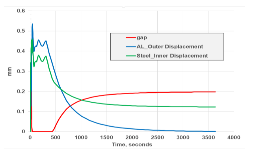
The internal defects were likely from a combination of forging folds and post forming temperature equalization. During the forming process, the hot steel is put into direct contact with cooler aluminum core. Once in direct contact, the aluminum temperature rises and the steel rapidly cools as the aluminum core “quenches” the shell. As the aluminum heats and the steel cools, the aluminum expands while the steel tries to contract. This puts significant tensile stresses on the internal surface of the steel while the steel shell falls below the AC1 temperature. Figure 16 shows the DANTE® software predictions for dimensional movement in the billet for the 26 second heating cycle for half inch billets if forming did not occur and the sample was allowed to air cool. The models show that the gap would go to zero. Once in contact, both the aluminum and steel contract in concert as temperature equalizes between the two components. The steel and aluminum dimensions grow again slightly as temperature equalizes in the aluminum. Finally, as the components cool the aluminum contracts at a greater rate than the steel and a significant gap develops (0.2 mm).
One can predict that the greater the temperature differential between the two components, the greater the post forming dimensional movement and stress level would be. Also, the thinner the steel wall, the larger temperature drop in the steel would be after forming. For the ¼” steel billets, this resulted in crack formation in the radius [1]. The cracks would form sometime after the forming process and the cracks continued to grow while the billets sat and cooled. On the converse, the lower the equalized temperature, the lower the post equalization contraction will be resulting in smaller shell core gaps. This was also evident in the trials [1].
After the hot forging trials, hot hydroforging experiments were conducted to resolve the issues related to temperature equalization. The bimaterial billet was heated to 1000-1250 C range with a high frequency induction heater as guided by the induction heating modeling. Aluminum was allowed to melt inside the steel without fracturing the steel case by a cyclic on/off control of the power of heater. During hot hydroforging the liquid core flowed effortlessly and provides a uniform hydrostatic pressure inside the steel thereby enabling a uniform deformation of the solid steel shell. Upon cross sectioning a hot hydroforged part, a uniform steel wall thickness was observed all around the part. However, there were also large voids in the aluminum core as expected. Using glass as the core material instead of aluminum will solve the void issue since glass has a matching CTE to steel. The benefits of matching thermal expansion behavior to eliminate shrinkage void had been demonstrated [1] by deformation modelling of induction heating and air cooling of steel-glass bimaterial billets.
Heating the steel-glass billets to forging temperatures will be simpler and faster than heating the steel-aluminum billets. It can be also envisioned that hot hydroforged steel-glass bimaterial gears can be quenched right after forging and be tempered by the latent heat of glass during the air cooling. The novel heat treatment procedure can save time and money by replacing the time consuming and costly carburizing and nitriding heat treatment procedures. Hence, the next series of hot hydroforging experimentation can be planned around the steel-glass material combination. Glass is 10% lighter than aluminum thereby providing further weight reduction benefits. These options need to be explored further.
On the other hand, aluminum core enables a novel concept of “investment forging” where the molten aluminum core can be emptied out of the part right after forging analogous to investment casting. A hollow part with uniform steel shell can be formed for ultimate weight savings. For example, investment forging of hollow steel valves for engine applications is feasible by hot hydroforging. In some cases the core can be emptied out later after creating evacuation holes at room temperature and reheating the part if it is difficult to empty the core right after forging. Any low melting substance that does not go into gas phase at forging temperatures is a candidate as the core in investment forging. Expensive core materials such as aluminum or magnesium that are extracted from the product during investment forging can be recycled.
The experimentation with hot hydroforging addressed several risk factors that had been identified and put into test. One of the concerns was if the degree of interference fit would have any impact on the quality of bimetal billet forging. The experiments indicated that an interference fit is not needed. Another concern was about the vulnerability of the weld seams to failure during forging. The experiments has shown that it is reasonable to expect that the weld zones of billet will heal and have no adverse effect on the performance of the end product upon hot hydroforging [1, 2]. These guidelines lead to significant cost savings for the preparation of billets in a mass production scenario.
Conclusions
Bimaterial forging is a new and exciting technology that has the potential to substantially reduce the weight of steel components used for many automotive powertrain components. Currently 100% of truck gears are made of steel. If the gears are forged from a bimaterial billet such as 50/50 steel/aluminum by volume than 33% weight reduction in gears is possible.
Our bimaterial gear concept has a steel shell on the outside and a lightweight core on the inside. The steel shell will carry most of the torque while the lightweight core serves as a space holder and reduces the weight of gear. The steel shell would have welded caps on top and bottom.
The initial lightweight core studied was aluminum. Due to the mismatch in CTE, it is necessary to get the weld seam in the austenitic phase quickly, so that it will be able to easily expand when the aluminum expands. This means that the heating process must be fast, so induction heating was selected as the heating method.
The method for modeling the induction heating process for steel aluminum bimaterial billets was demonstrated. The modeling method involved coupling the electromagnetic and thermal program Flux2D™ with the thermal, structural, stress and dimensional movement program DANTE®. The results showed that using induction heating, it was possible to successfully heat the components without risking cracks to the weld seam during heating. Experimental validation of the heating process was conducted and the experimental results agreed very well with the modeling predictions.
One selected case was demonstrated in this paper; however, a number of different heating scenarios were both modeled and tested. These models all showed good agreement with the experimental predictions. This means that the modeling is scalable and can be used to predict results with different core materials or core phase (i.e., hot hydroforging).
In the future, it is anticipated that the results of the Flux2D™ and DANTE® software models should be coupled with additional modeling packages for subsequent manufacturing steps. The DANTE® software results could be used as an input for forming simulation. Forming simulation would be followed by cooling simulation. Cooling simulation could be followed by modeling of the subsequent machining, heat treatment and final loading to determine the component performance.
Acknowledgments
This research was funded and conducted at the Corporate Research and Technology Group at Eaton in Southfield, MI. Billet induction heating simulations, thermal profile design and validation support were provided by Fluxtrol Inc. in Auburn Hills, MI. The high frequency induction power supply was provided by Interpower Induction Services Inc. Fraser, MI. Forging services were provided by Walker Forge Inc. in Clintonville, WI. Further billet heating, cooling and deformation modeling were provided by DANTE Solutions Inc. in Cleveland, OH. The authors would like to thank following team members for their contributions: Dr. Xi Yang, Mike Killian from Eaton, Jake Butkovich, Dr. Peter Fritz from Eaton.
References
[1] B. Chavdar, R. Goldstein, X. Yang, J. Butkovich, L. Ferguson, “Hot Hydroforging for Lightweighting”, IDE 2015; Bremen, Germany; Sep. 23-25, Vol. 5, pp. 117-128
[2] B. Chavdar, R. Goldstein, L. Ferguson, “Hot Hydroforging for Lightweight Bimaterial Gears and Hollow Products”, 23rd IFHTSE Congress; Savannah, GA -USA; April 18-22, 2016.
[3] V. Nemkov, et. al, “Stress and Distortion Evolution during Induction Case Hardening of Tube”, 26th ASM International Heat Treating Society Conference, Cincinnati, OH USA; October 31 – November 2, 2011.
[4] Li, et.al, “Effect of Spray Quenching Rate on Distortion and Residual Stresses during Induction Hardening of a Full-Float Truck Axle”, 27th ASM International Heat Treating Society Conference, Indianapolis, IN USA; September 16-18, 2013.
If you have more questions, require service or just need general information, we are here to help.
Our knowledgeable Customer Service team is available during business hours to answer your questions in regard to Fluxtrol product, pricing, ordering and other information. If you have technical questions about induction heating, material properties, our engineering and educational services, please contact our experts by phone, e-mail or mail.
Fluxtrol Inc.
1388 Atlantic Boulevard,
Auburn Hills, MI 48326
Telephone: +1-800-224-5522
Outside USA: 1-248-393-2000
FAX: +1-248-393-0277