Information
Authors: Bulent Chavdar, Robert Goldstein, Xi Yang, Jacob Butkovich, Lynn Ferguson
Location/Venue: IDE 15 Bremen, Germany
Topic: Bi-metal Hydroforging
Download Presentation PDF
Abstract
Feasibility of making lightweight powertrain products with hot hydroforging of steel/low density material hybrid billets is explored. A bimaterial billet is designed such that a steel shell encloses a low density core 100%. Furthermore the low density core is selected among the materials that have lower melting or softening temperature than steel such as aluminum and glass. In hot hydroforging the bimaterial billet is heated to 1000-1200 C range similar to the conventional hot forging of steel. However, in hot hydroforging the core is in liquid or viscous state while steel shell is in solid state similar to the conventional hydroforming. During hot hydroforging the viscous/liquid core has negligible resistance to flow thereby providing a uniform hydrostatic pressure inside the steel and enabling a uniform deformation of the solid steel shell.
Introduction to Hot Hydroforging
Bimaterial products can be hot forged from a bimaterial billet where the steel shell encloses the lightweight core fully. A bimaterial billet can be forged in solid state however a better forging quality can be achieved if the core material is viscous thereby providing uniform hydrostatic pressure to steel shell during forging similar to a hydroforming process. However, the similarity only pertains to the hydrostatic pressure developed inside the deforming billet not to the process temperatures. While hydroforming is done at room temperatures the hot hydroforging is done at temperatures greater than 1000C enabling deformation of steel into intricate topologies without a fracture. Other differences between the hydroforming and hot hydroforging are that the amount of fluid is constant in hot hydroforging and the fluid may solidify and become an integral part of the product after forging and cooling. The lightweight core material will need to have a lower melting or softening temperature than the steel for hot hydroforging. Aluminum, magnesium, and glass are such candidate lightweight materials.
Our lightweight bimaterial gear concept includes a lightweight core material that is fully enclosed in a steel shell and formed into the teeth area thereby interlocking with the steel in the interior and contributing to the transfer of torque during the operation of gear. The formation of mechanical interlocking reduces the need for metallurgical bonding between the steel and the lightweight core. The concept gear has all around steel surfaces that engage with the mating gear at the outer diameter and the shaft at the inner diameter. It is envisioned that the steel frame would carry the bulk of torque from one component to the other and also would provide a long fatigue life to the gear. Furthermore steel surfaces could be induction hardened to withstand high Hertzian contact stresses. On the other hand the lightweight core would serve as a continuum to transfer stresses inside the steel thereby providing rigidity and reducing risk of plastic deformations to the steel shell under loading. References 1 and 2 describe bimetal gears where steel does not enclose aluminum 100% and the torque transfer has to go through the steel, and the aluminum in a serial configuration. Each component has to bear 100% of loads individually and they have to form a strong intermetallic bond. In our concept the loads are shared by the steel and the lightweight core. Furthermore, the torque is transferred from one component to the other mostly by mechanical interlocking. In Ref. 3 a C15 steel was cladded with 316L stainless steel and forged in solid state. Although the application did not have a light weighting purpose it stressed the importance of friction condition at the die/billet interface that had a great impact on the final material distribution, forging loads and cracking occurrence. In Ref. 4 two semisolid alloys were mixed at micro level uniformly, then heated the bimaterial mixture between their liquidus and solidus temperature before forging. In the bimaterial hot hydroforging process two materials are not mixed. Hot hydroforging is also fundamentally different from the squeeze casting or liquid forging process where the molten material is poured into the bottom half of die and solidified under pressure (5,6). In hot hydroforging the molten material is always contained within the solid steel shell of a billet and never contacts the die.
In this study the feasibility of hot hydroforging was investigated by modeling and also experimentation. Induction heating simulations of bimaterial billets were conducted on ELTA (1D) and FLUX (2D and 3D) software. The stress state, dimensional changes and phase changes that occur during heating and cooling of bi-material billets were simulated using the DANTE heat treatment software. The hot forging and the hydroforming simulations of bimaterial billets were conducted on the DEFORM software. The steel/aluminum bimaterial billets were designed and prepared. A three piece closed die was designed and made for hot hydroforging experimentation. Hot forging and hot hydroforging experiments were done on bimaterial billets. The results were discussed and the future directions were identified.
Enabling Net Shape Gear Forging
Heavy duty manual transmissions require large size spur gears and helical gears made of carburizing steel. Most forged gears are made by two step manufacturing processes, hot forging followed by machining. First a tall cylindrical billet of steel is hot-forged to a flat pancake shape and then a center hole and the teeth are formed by machining. Forty five percent of the starting material is wasted in the machining operations where the most waste is due to the teeth machining. The near net shape forged steel gears with light weight core can enable an 80% reduction in machining, thereby saving 2 to 4 kg waste per an average size gear. The raw material cost of a steel gear with light weight core may be significantly less than that of a gear produced from a solid steel billet because the volumetric cost of the light weight core can be lower than the cost of steel that is replaced. The reduction in waste also has a potential to reduce the carbon foot print of gear manufacturing operations.
Hot hydroforging concept is an enabler for a near net forging of large gears with the teeth from lightweight bimaterial billets. Figure 1 shows the cross-sections of the concept of bimaterial gear where the outer structure is made of 100% steel and the inner structure is 100% lightweight core. Figure 2 shows the assembly of the bimaterial billet by fitting the aluminum core in a steel tube and welding two steel end caps to the steel tube. Figure 3 shows the initial concept of hot hydroforging a bimaterial gear in a two blow forging operation. In the first blow a pancake shape is forged and in the second blow the teeth and the center hole are forged.
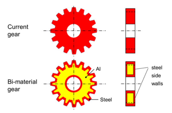
Figure 1: Bimaterial gear concept. The outer structure is steel, the inner structure is a lightweight material.
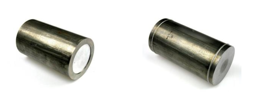
Figure 2: Steel-aluminum bimaterial billet where an aluminum core is inserted into a steel tube on the left and two steel end caps are welded to the tube to complete the assembly on the right.
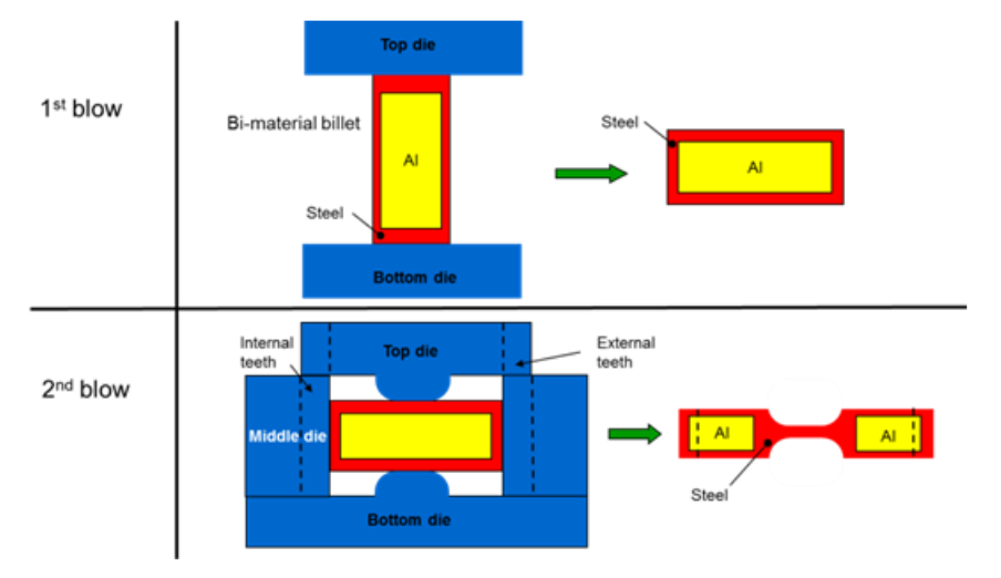
Figure 3: Hot hydroforging concept of net shape gear forging with teeth and the center hole.
Simulations of Heating and Hot Hydroforging of Steel-Aluminum Billet
The induction heating simulations included the calculations of temperature distributions, thermal gradients, estimation of processing speeds and estimation of equipment costs. Induction heating simulations of steel-aluminum bimaterial billet were conducted to determine the thermal gradients needed during the induction heating on ELTA software. In order to prevent the cracking of bimetal billet, the steel wall needs to be heated and expanded away from the aluminum core before aluminum is heated. The steel needs to reach above recrystallization temperatures before aluminum expands and catches up with the steel wall to prevent any cracking in the steel. When the steel is well above the recrystallization temperature even if aluminum catches up with the steel and exerts pressure on the steel it does not cause a problem since then steel can deform outwards easily to accommodate the expansion of aluminum without any fracturing. Figure 4 shows that the steel wall is heated above the recrystallization temperature with the on/off control of the induction heater. Steel is heated above the recrystallization temperature in 10 seconds in the first cycle and gradually increases to the 1100-1300C range in 6 cycles while the aluminum core is still in solid state in the first two cycles. The modeling assumes that steel and aluminum maintain contact during the expansion. Figure 5 shows that after 6 on/off cycles in 60 seconds the center of aluminum core reaches 1000 C and the OD of steel cools down to 1000 C reaching an equilibrium temperature in the billet. In reality, when steel expands away and loses contact with the aluminum core the temperature of aluminum will increase slower than the case shown in Figure-4 and 5 and a few more on/off cycles will be needed to increase the aluminum core temperature to 1000 C.
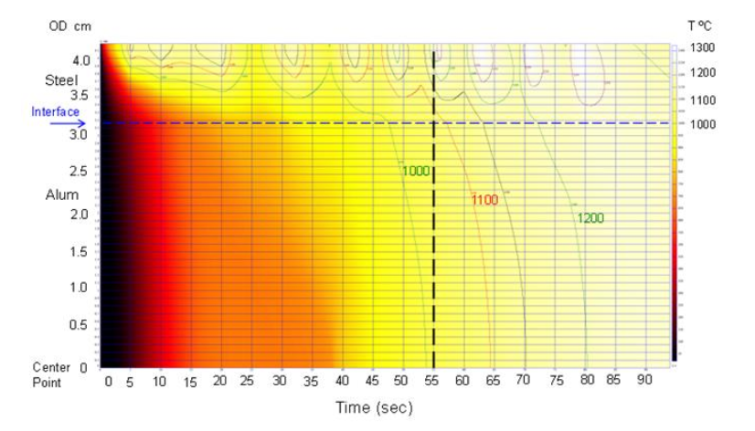
Figure 4: Iso-temperature lines showing the temperature distribution in the radial direction from the center axis to the outer diameter of the billet at mid height of the billet as function of the heating time. The heating simulation shows the effect of on/off control strategy
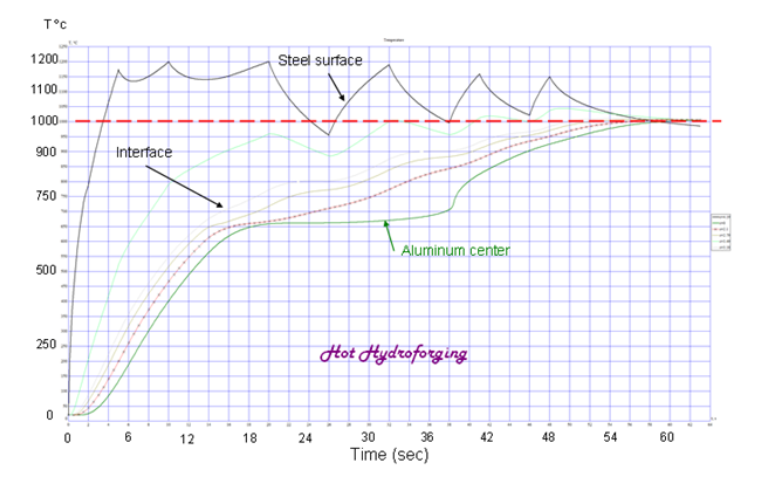
Figure 5: Heating simulation shows that aluminum core reaches 1000C in 6 on/off cycles in 60 seconds.
Forging modeling of bimaterial gear is accomplished by 2D and 3D forging simulations on DEFORM software. The modeling work included 2D simulations of open and closed die upset forgings and 3D simulations of closed die forging with the teeth. The objectives of forging simulations are to establish the feasibility of forging the gear teeth, to estimate press loads, tooling and manufacturing costs, to investigate the steel wall thickness uniformity and to optimize forging temperatures, loads and speeds with alternative core materials. Initially the most of forging modeling is done in solid state assuming a forging temperature of 1000-1100C for the steel wall and 400C for aluminum core since DEFORM software is initially coded to model the forming of materials in solid state only during forging simulations. Later on 3D simulations of hot hydroforging were conducted by providing a uniform hydrostatic pressure inside the hot steel shell by hydroforming simulation as shown in Figure 7.
Figure 6 shows the closed die design for the pancake forging where the top and the bottom end zones of billet are protected in pockets created in the top and the bottom die plates. Modeling predicted that folding in steel wall and separation of steel and aluminum would occur at the interface between steel and aluminum during and after the solid state forging (Fig. 6 right). Furthermore excessive thinning was also predicted at the inside corner of the pancake when the steel flows around the corner radius of middle die with the solid state forging. In contrast, hot hydroforging eliminated any separation or folding on the bore of steel as shown in 3D simulations in Figure 7 due to the uniform hydrostatic pressure on the bore.
The hot hydroforging simulations were carried out one step further to investigate the feasibility of creating a uniform steel wall thickness around the tooth profile of a gear. A non-uniformity index of wall thickness is defined by the ratio of the highest and the lowest values of steel wall thickness located at the apex and the root respectively in a tooth profile. The value of non-uniformity index corresponding to a uniform steel wall thickness all around the tooth is one.
An advanced hot hydroforging concept was conceived that included a halfway forging of the teeth in a closed die in the first blow and then indexing the preform by a half tooth width in the circumferential direction and then completing the teeth forging in another closed die as shown in Figure 8. Two-blow indexed hot hydroforging not only enables a uniform steel thickness around the tooth profile but also enables targeting a thicker steel wall at the root area where the largest bending stresses occur in a gear under the load than the steel wall at the apex area. The non-uniformity index is 1.3 with 2-blow hot hydroforging as shown in Figure 9.a. Furthermore, a thick steel wall observed below the pitch line and a thin steel wall is observed above the pitch line on the flank of tooth thereby reducing the risk of bending fatigue at the root of tooth.
Solid state forging simulation with a steel wall temperature at 1100C and the aluminum core temperature at 400C showed a miniscule penetration of aluminum into the tooth cavity as in Figure 9.b. Excessive thinning of steel wall is observed at the root of tooth with a resulting non-uniformity index of 6.7. On the other hand 2-blow indexed hot hydroforging enabled penetration of aluminum into the tooth area. The ratio of aluminum to steel in the tooth cross section is increased significantly in hot hydroforging thereby increasing the weight reduction further.
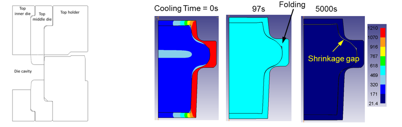
Figure 6: Left: Closed die design for pancake shape forging. The pockets in the top and the bottom dies keeps the weld zone of end caps under compression during forging. Right: Solid state forging simulation.
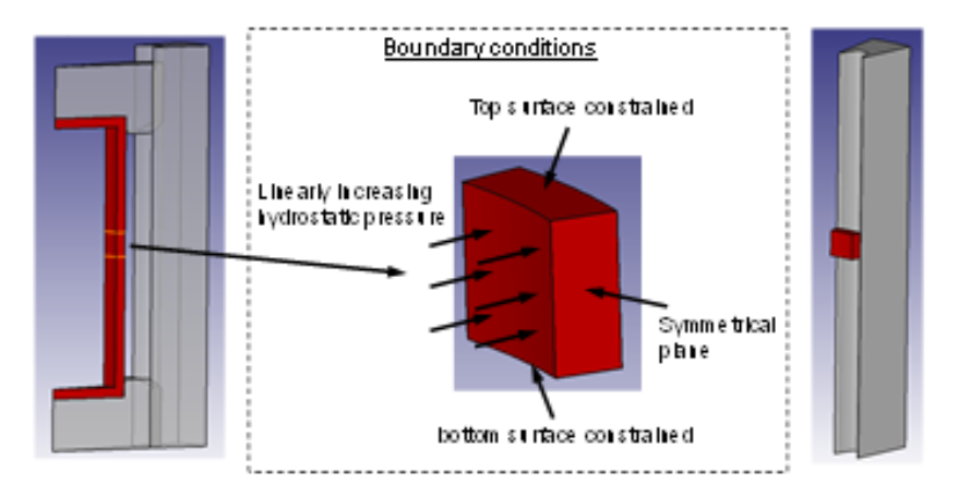
Figure 7: Boundary conditions for hot hydroforging simulations with hydrostatic pressure on ID of steel.
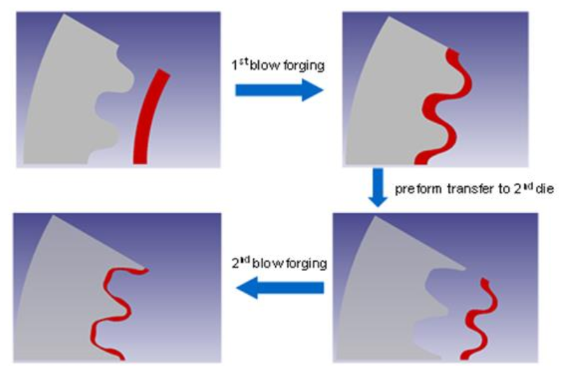
Figure 8: Simulations of two-blow, indexed, hot hydroforging of net shape gear teeth in DEFORM. The steel wall is red and the dies are gray in the pictures. The core is replaced by a hydrostatic pressure at the ID of steel in simulations. The teeth profile is formed half way in the first die (top). The preform is indexed by half width of tooth and placed in the second die for final forging (bottom).
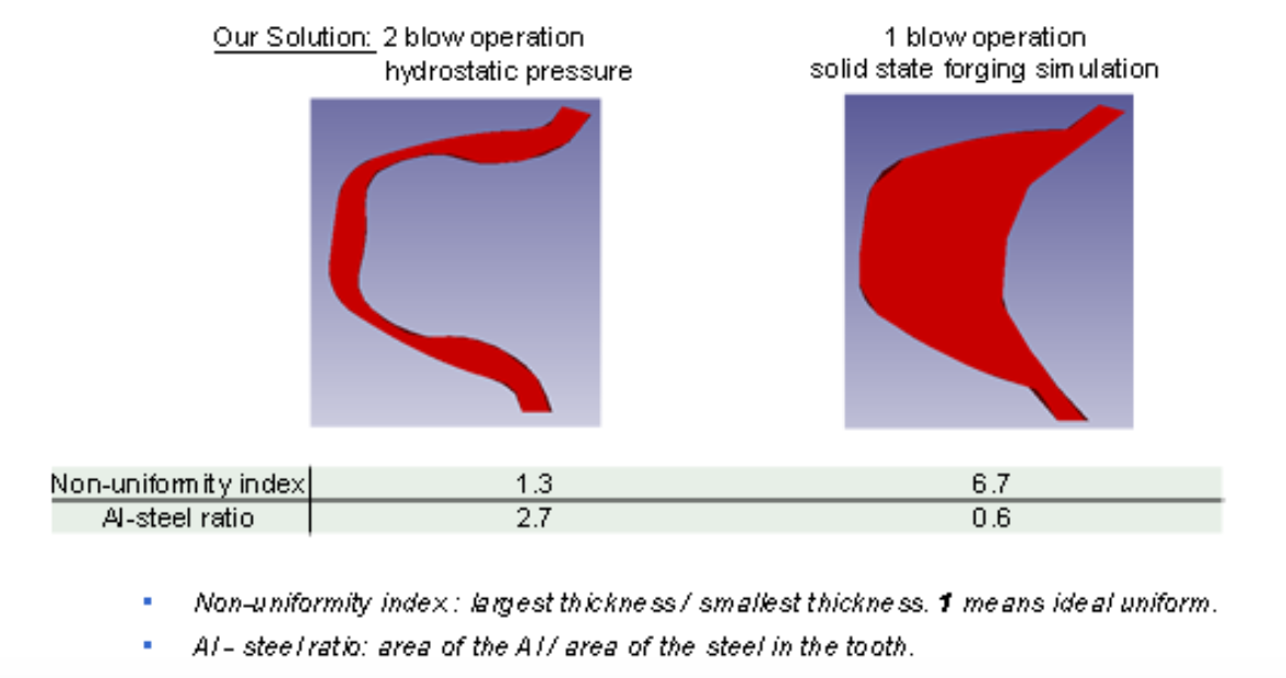
Figure 9: Simulations indicate that the steel wall thickness uniformity can be improved significantly with 2-blow, indexed, hot hydroforging as compared to 1-blow solid state forging.
Experiments of Hot Hydroforging of Steel-Aluminum Billet
SAE-1020 steel and Al-7075 were selected as the shell and the core materials of the bimaterial billet. The billets are designed with 0.25” (6.3 mm) and 0.5” (12.5 mm) steel wall thickness for experimentation with hot hydroforging and solid state forging. A billet with half inch steel wall is shown in Figure 2. Steel tubes with 3.5” (88.9 mm) diameter are cut in 6” (152.4 mm) lengths. Aluminum cores with matching diameter are fit inside the tubes and the both ends of the tube is welded shut by electron beam welding. Special care is given to avoid air pockets inside the fully assembled billets. The end cap weld zones are identified as the high risk areas for structural failure, a closed die design was conceived as shown in Figure 7 that the end zones of billets are confined in die pockets that prevented the deformation of heat affected zones during pancake forging. Several bimaterial billets were also forged in solid state for comparison.
Since aluminum has a much higher coefficient of thermal expansion than steel, 22 vs 12 (x10-6 m/m C), the steel must be heated sooner than the aluminum to avoid thermal stress cracking of the billets. A 10 kHz 500 kW power induction heating system is designed and constructed to be able to heat the billets with the right thermal gradient. The steel/aluminum bimaterial billets were heated with repeated on/off cycles to a forging temperature of 1100-1200C in roughly 2 minutes. The maximum steel wall temperature reached to 1300C when power on.
Both the billets with 0.25" and 0.5" steel wall thickness were forged successfully in that the steel wall thickness was uniform all around after the hot hydroforging as compared to solid state forging as shown in Figure 10. The steel wall thickness was much more uniform than the case of solid state forging overall. The steel wall thickness was thinned around the corner radius of the middle die but did not fracture with hot hydroforging as it did in solid state forging.
Large shrinkage voids formed in the aluminum core after hot hydroforging due to the CTE mismatch. Aluminum shrinks much more than steel does during cooling. Furthernore, the volume of aluminum contracts 6% when its phase changes from liquid to solid. These two effects contribute to the voids in the aluminum core. Since the voids in the core are not desirable a different material than aluminum needs to be selected as the core. Experiments with aluminum core were useful to demonstrate the steel wall thickness uniformity in hot hydroforging.
A significant healing of the microstructure of the weld zone was observed after the hot hydroforging. Figure 11 compares the microstructure of the weld zone of the electron beam welded steel end cap and the steel tube before and after the hot hydroforging. The dendritic directional grains of the weld bead and the coarse-graining of the heat affected zone disappeared upon hot hydroforging.
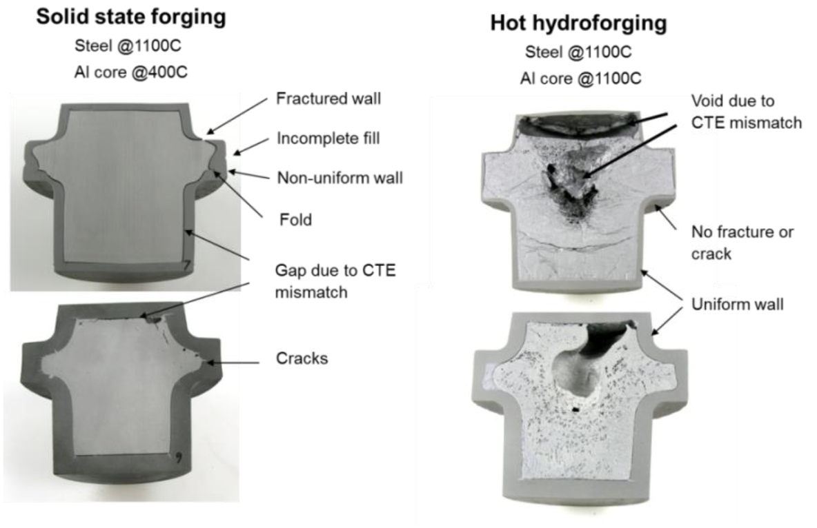
Figure 10: Pancake forging experiments of bimetal billets in solid state (left) and in hot hydroforging (right). The top pictures are of billets with 0.25” wall and the bottom pictures are of billets with 0.5” wall.
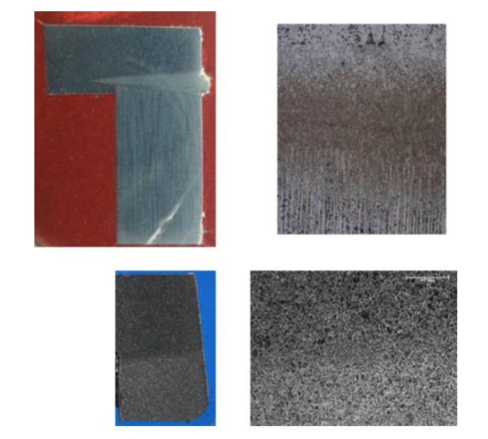
Figure 11: The macro and micro structure of the weld zone between the steel end cap and the steel tube before (the top pictures) and after (the bottom pictures) the hot hydrofroging show that the weld zone healed after hot hydroforging.
Modeling Results for Heating and Cooling Steel-Glass Billets
The large difference between the CTE’s of the steel and aluminum caused void in the core. One idea was to use a low density core material with a CTE that was more similar to that of the steel cylinder. Conventional soda lime glass was identified as a possible low density core material. This section briefly describes model results of an induction heating and air cooling cycle.
The transient power data generated by FLUX-2D induction heating model were mapped to the mesh used in the DANTE heat treatment software to predict the metallurgical phase changes, dimensional changes and stress state during the induction heating and air cooling steps of the transient thermal model. Figure 12 shows plots of nodal histories for the first 800 seconds of processing time. Table 1 has model predicted values for selected nodes at specified process times. These figures and the table data help to understand the benefit of having a similar CTE for the two materials. Figure 12 shows histories at mid-height of the glass-steel radial interface for temperature (left), radial displacement, the gap size and austenite fraction (right). The steel outer surface heats faster than the bore, as expected, and therefore transforms to austenite before the bore. A gap develops between the glass and the steel cylinder because of the faster heating of the outside of the steel cylinder, but this gap is predicted to close during the air cooling. A gap also opens at the top interface between the glass and steel. The faster heating of the steel outer skin and the longer length in the axial direction causes the gap to form. However, while the gap decreases initially during air cooling, the final phase transformation of the austenite to ferrite and pearlite re-widens the axial gap and there is predicted to remain a gap after complete cooling. Table 1 shows this difference between the radial and axial locations. The final axial gap is small and isolated to the center of the top interface.
| Mid-Height Location: Steel-Glass Interface | Top Center Location: Steel-Glass Interface | |||||
|---|---|---|---|---|---|---|
| Total Process Time (s) | Steel Bore Temperature, C | Glass Outer Temperature, C | Radial Gap, mm | Steel Lid Temperature, C | Glass Top Temperature, C | Axial Gap, mm |
| 0 | 20 | 20 | 0.0 | 20 | 20 | 0.0 |
| 26 | 877 | 871 | 0.232 | 571 | 578 | 0.945 |
| 126 | 760 | 761 | 0.0 | 742 | 742 | 0.189 |
| 277 | 559 | 559 | 0.072 | 535 | 535 | 0.474 |
| 667 | 170 | 170 | 0.0 | 165 | 165 | 0.153 |
| 3636 | 20 | 20 | 0.0 | 20 | 20 | 0.100 |
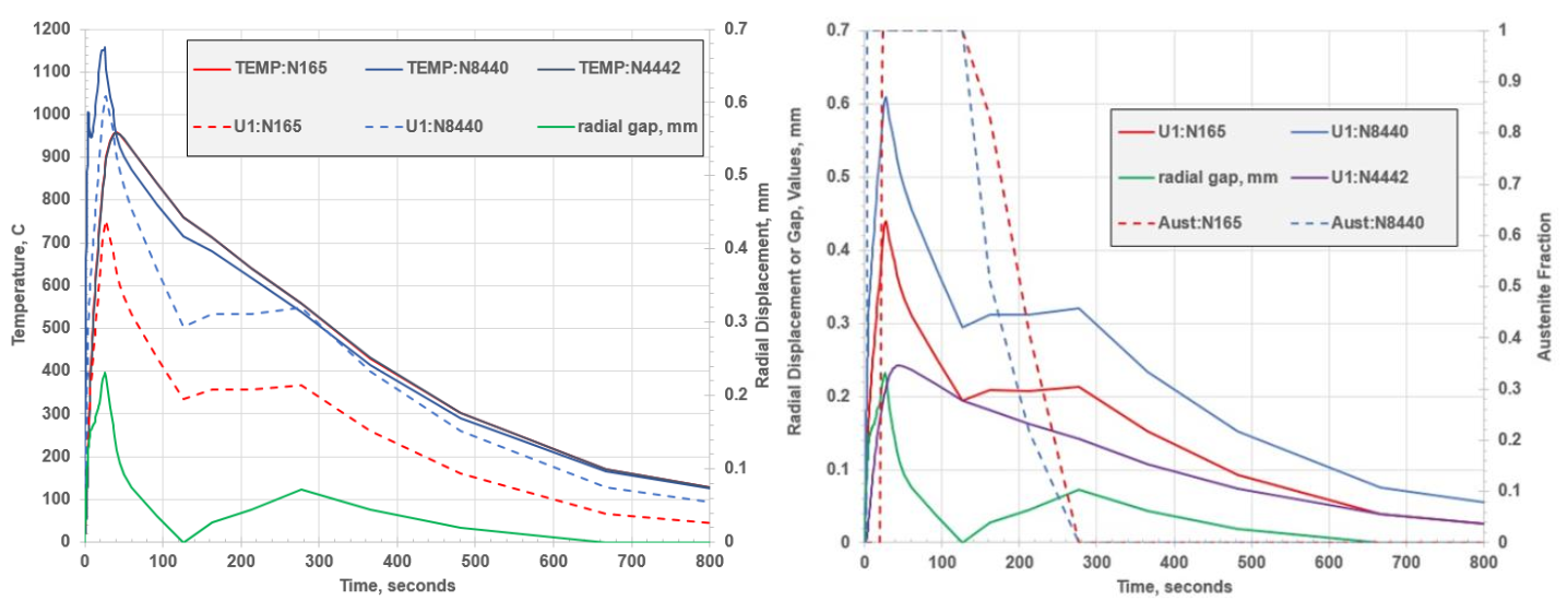
Figure 12: Histories of temperature, radial displacements, radial gap and austenite fraction (right) between the bore of the steel cylinder and glass core at mid-height for 800 seconds of process time. N165 is on steel bore, N8440 is on outside of steel cylinder, and N4442 is on outer surface of glass
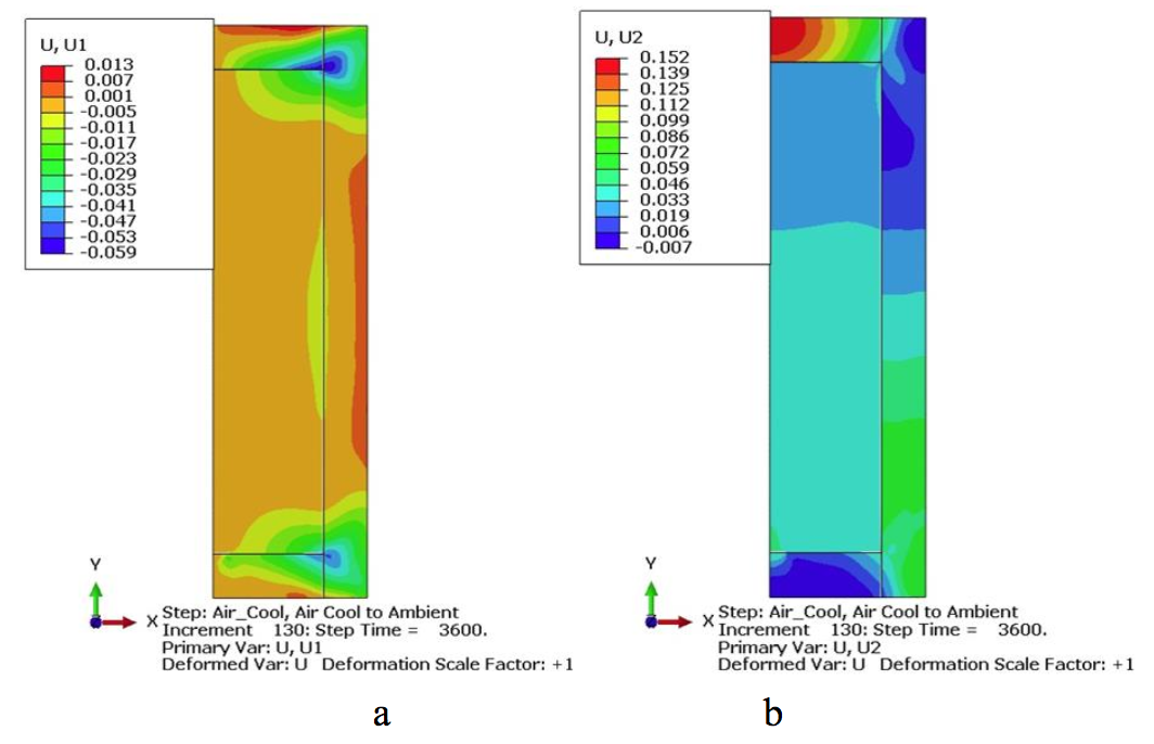
Figure 13: Predicted final (a) radial and (b) axial displacements for the steel–glass bi-material billet
Figure 13 shows the predicted displacement profiles at the end of the heating and cooling process. From the profiles, it can be discerned that no radial gap exists between the glass and steel. However, there is a small gap at the bottom glass-steel interface of about 0.01 mm and at the top interface of 0.100 mm.
Discussions
Lightweighting is an energy saving strategy for the transportation industry. Transmission and driveline components account for 5-10% weight of a typical class 7/8 tractor. The gears account for 20% weight of a heavy duty manual transmission. Currently 100% of truck gears are made of steel. If the gears are forged from a bimaterial billet such as 50/50 steel/aluminum by volume than 33% weight reduction in gears is possible. This translates into 0.5% reduction in the weight of a truck and 0.2% improvement in the fuel efficiency.
The torque capacity of a gear can be increased by increasing the size of gear and also by forging instead of by machining. Small gears can be forged since their press loads are manageable. However, most big gears are made by machining instead of forging due to big forging press requirements. Hot hydroforging enables forging of large gears on the existing presses due to the reduced press loads.
Feasibility of making lightweight gears with hot hydroforging of steel/low density material hybrid billets is explored for powertrain applications. The functional requirements of gears are determined for transmission applications. An integrated computational engineering approach is followed to determine the theoretical weight reduction targets that meet functional requirements. Design and testing methods are developed to mitigate the risks. Our bimaterial gear concept has a steel shell on the outside and a lightweight core on the inside. The steel shell will carry most of the torque while the lightweight core serves as a space holder and reduces the weight of gear. Two material options are identified for the low density, low melting core: aluminum and glass. Both materials are relatively low cost and readily available. Aluminum is a lightweight metal and second to the steel in terms of the availability and the cost. However there are many risks and challenges when aluminum and steel are used together in a structural product such as a gear. The biggest technical challenge is due to the difference in the coefficients of thermal expansion (CTE) of steel and aluminum. The CTE of aluminum is twice the CTE of steel. Furthermore, the volume of aluminum increases upon melting. These two factors contribute to the formation of shrinkage voids in the core upon cooling after a hot hydroforging. After conducting intensive digital prototyping efforts, the experimental studies were carried out to prove the concepts.
For the experimental phase, steel/aluminum bi-metal billets were prepared. Then, the bimetal billets were hot hydroforged into a so called "pancake" shape inclosed dies in one blow. In hot hydroforging experiments the bimaterial billet was heated to 1000-1200 C range with a high frequency induction heater as guided by the induction heating modeling. Aluminum is allowed to melt inside the steel without fracturing the steel case by a cyclic on/off control of the power of heater. During hot hydroforging the liquid core flows effortlessly and provides a uniform hydrostatic pressure inside the steel thereby enabling a uniform deformation of the solid steel shell. Upon cross sectioning a hot hydroforged part, a uniform steel wall thickness was observed all around the part. However, there were also large voids in the aluminum core as expected. Using glass as the core material instead of aluminum will solve the void issue since glass has a matching CTE to steel. Preliminary deformation modelling of heating and cooling of steel-glass bimaterial billets demonstrated the benefit of matching thermal expansion behaviour as closely as possible to reduce or eliminate any void in the core. Hence, the next series of hot hydroforging experimentation can be planned around the steel-glass material combination. Glass is 10% lighter than aluminium thereby providing further weight reduction benefits. Heating the steel-glass billets to forging temperatures will be simpler and faster than heating the steel-aluminium billets. Furthermore, low cost bimaterial billets may be prepared with sand in the core as the raw material of glass. The sandy core may have uniform porosity leading to further weight reductions. These options need to be explored further.
On the other hand, aluminum core enables a novel concept of “investment forging” where the molten aluminum core can be emptied out of the part right after forging analogous to investment casting. A hollow part with uniform steel shell can be formed for ultimate weight savings. For example, investment forging of hollow steel valves for engine applications is feasible by hot hydroforging. In some cases the core can be emptied out later after creating evacuation holes at room temperature and reheating the part if it is difficult to empty the core right after forging.
The experimentation with hot hydroforging addressed several risk factors that had been identified and put into test. One of the concerns were if the degree of interference fit would have any impact on the quality of bimetal billet forging. The experiments indicated that an interference fit is not needed. Another concern was about the vulnerability of the weld seams to failure during forging. The experiments has shown that it is reasonable to expect that the weld zones of billet will heal and have no adverse effect on the performance of the end product upon hot hydroforging. These guidelines lead to significant cost savings for the preparation of billets in a mass production scenario.
Conclusions
Breakthrough technological advances require out of box thinking and reasonable risk taking. Hot hydroforging of bimaterial billets is an out of box idea and carries some risks. However, intensive modeling and digital prototyping approach of this research reduced the risks to a reasonable level. The following novel forging ideas were proposed in this paper:
- Hot hydroforging for lightweighting, net shape forging and waste reduction with steel-glass billets
- Investment forging for hollow products of steel, titanium, copper alloys etc. with the low melting metals or alloys at the core such as aluminium, magnesium etc.
Steel/aluminum bimetal billets were prepared. Then, the bimetal billets were hot hydroforged in closed dies in one blow. A uniform steel wall thickness was observed all around the forged part upon cross sectioning. However, there were also macro voids in the aluminum core. The voids are formed due to the CTE mismatch between steel and aluminum and the volume increase of aluminum during phase change. The voids can be eliminated if aluminum is replaced by glass that has a matching CTE to that of steel. Furthermore, glass is not fully melted at forging temperatures thereby mitigating the risks of phase change.
On the other hand the molten aluminum core can be emptied out of steel shell after forging thereby giving rise to the novel concept of "investment forging". A hollow part with uniform steel shell can be formed for the ultimate weight and cost reductions. For example investment forging of hollow steel valves for engine applications is feasible by hot hydroforging and needs to be explored further.
References
[1] B. –A. Behrens, K. –G. Kosch: Development of the heating and forming strategy in compound forging of hybrid steel-aluminum parts, Mat. –wiss. U. Werkstofftech, Vol 42, No 11, 2011, p. 973-978.
[2] B. –A. Behrens, K. –G. Kosch: Production of Strong Steel-Aluminum Composites by Formation of Intermetallic Phases in Compound Forging, Steel Research International, Vol 82, No 11, 2011, p. 1261–1265.
[3] Jincai W, Langlois, L., Rafiq, M., Bigot, R., Hao , L.: Experimental &Numerical Study of the Hot Upsetting of Weld Cladded Billets, Key Engineering Materials, Vol 554-557, No 1, 2013, p. 287-299.
[4] Yang, Z., Dong, J., Zhou, L., Shen, L., Zhang, W.: A Study of the method of Manufacturing Bimaterial Composite Parts Through Semisolid Metal Processing, Metallurgical and Materials Transactions A: Physical Metallurgy and Materials Science, Vol 42, No6, 2011, p. 1709-1716.
[5] Luo, S., Jiang, J., Wang, Y., Teng, D.: Mechanics and forming theory of liquid metal forging, Trans. Nonferrous Met. Soc. China, Vol 13, No 2, 2003, p 369-375.
[6] Zhi-ming, D., Gang, C., Fei, H., Guang-xiang C., Jun L., Hong-wei, L., Xin Z., Shui-sheng, X.: Homogenization on microstructure and mechanical properties of 2A50 aluminum alloy prepared by liquid forging, Trans. Nonferrous Met. Soc. China, Vol 21, 2011, p 2384-2390.
If you have more questions, require service or just need general information, we are here to help.
Our knowledgeable Customer Service team is available during business hours to answer your questions in regard to Fluxtrol product, pricing, ordering and other information. If you have technical questions about induction heating, material properties, our engineering and educational services, please contact our experts by phone, e-mail or mail.
Fluxtrol Inc.
1388 Atlantic Boulevard,
Auburn Hills, MI 48326
Telephone: +1-800-224-5522
Outside USA: 1-248-393-2000
FAX: +1-248-393-0277