Information
Authors: Robert Goldstein, Bernd-Arno Behrens, Deniz Duran
Location/Venue: ASM HTS 17 Cleveland, OH
Topic: Tailored Forming
Download Presentation PDF
Abstract
The demand for lightweight, high performance components continues to grow in the transportation industry. However, the inevitable trade-off between strength, weight and cost is a limiting factor in design and implementation of many technologies. Load adapted tailored components with locally varying properties offer a potential solution to this problem. In sheet forming industry, use of tailored blanks has increased notably in the last two decades, whereas utilization of such concept is relatively new to bulk metal forming industry. The researchers have been exploring new possibilities for suitable process chains to manufacture massive hybrid components. The process chain involves manufacturing processes of joining, forming, heat treatment and machining. The interface characteristics between the two materials are decisive in the performance of the manufactured component. In this study, manufacturing of a bi-material shaft by tailored forming is covered. First of all, an overview of the tailored forming technology is given with an emphasis on the joining zone treatment by thermal and thermomechanical processing. In the following, a numerical and experimental analysis of induction heating of bi-material workpieces is presented.
Introduction
Vehicular manufacturers and their suppliers are constantly being challenged to improve fuel efficiency, without sacrificing performance or increasing the cost. One of the ways to achieve fuel efficiency improvements is to reduce the weight of components. Removing material from non-load bearing areas, changing materials and changing heat treatment specifications are common methods being employed in the field to try to achieve these goals. Oftentimes, seemingly minor changes can lead to major complications to the manufacturing process, leading to a substantial increase in the component cost for a relatively minor weight reduction.
Bi-material products are of interest to manufacturers, because they have the potential to offer significantly higher strength to weight ratios than components made of only one material. The challenge is how to ensure the integrity of the two materials under loading. One concept being explored is to produce bi-material products using the tailored forming technology. Theoretical studies using computer simulation and experimental trials have been conducted to develop a process for manufacturing bi-material shafts using a combination of tailored forming technology plus subsequent machining and selective heat treatment. The bi-material workpieces in this work consist of an aluminum billet (AA-6082) friction welded to a steel billet (20MnCr5).
During friction welding, some physical phenomena take place at the interface of the two materials. Fe-Al type intermetallic phases form, which can be very hard and brittle. Moreover, high heating/cooling rates occur which is accompanied by a non-uniform straining at a shallow layer. Therefore, a non-homogeneous grain structure appears after joining and a sharp transition of the mechanical properties from the joining zone through the bulk of the material is observed. Thus, the forming step in the process chain has to be designed in a way that the joining zone integrity can be maintained and that its properties can be improved through controlled thermal processing prior to forming as well as thermomechanical processing during forming.
Based on the preliminary experiments and forming simulations, it is supposed that the best joining zone properties are achieved when the steel and aluminum are heated to substantially different temperatures in order to obtain an admissible material flow during forming. Induction has been preferred as the thermal processing method since it is possible to achieve high heating rates and numerous strategies can be pursued to generate a non-homogeneous temperature distribution along the bi-material workpiece. In addition, the extrusion tooling has to allow a good control over the joining zone during forming and sufficient plastic straining has to be ensured.
In this study the feasibility of thermal processing of bi-material billets were investigated by modeling and also experimentation. Induction heating simulations of bi-material billets were conducted using ELTA™ and Flux™ 2D software. The steel/aluminum bi-material billets were designed and prepared for temperature measurement during induction heating experiments. An experimental setup was built along with some dedicated components. Experimental temperature readings were compared with the simulation results and the findings were discussed.
The goal of this paper is to understand and validate the thermal process necessary to produce a bi-material shaft by tailored forming. The proper thermal, metallurgical and dimensional results are necessary in order to correctly design the forming process. The forming process and results will be discussed and the future directions will be identified and presented more in depth in future publications.
1. Survey of Existing Research Works
In sheet metal forming industry, tailored blanks are semi-finished workpieces with selectively varied material characteristics and/or geometrical properties. They do not only advance lightweighting but also act efficiently to meet a particular requirement. After tailored blanks had been introduced to the market, there had been notable increase in the demand for auto body components year by year until the technology became well-established in the industry. A comprehensive review on tailored blanks has been done by Merklein et al. [1].
For bulk metal forming industry, a concept similar to tailored blanks is still unconventional. However, the number of studies in the field is on the increase. Numerous examples can be found in the reviews done by Mori et al. [2] and Groche et al. [3] on the joining processes involving plastic deformation. In the current survey, the approaches for fabricating bi-material three dimensional components are classified in two groups:
- Bi-material workpiece is obtained via a simple arrangement or a mechanical assembly. A metallurgical bond does not exist in this stage. An actual coalescence is expected to take place during the forming process.
- Bi-material workpiece is obtained by a joining process which means that the coalescence between the materials had already been established before the forming process. An improvement in the bonding strength as well as in the overall component quality can be achieved by the forming process.
This survey revealed that the studies in bi-material processing are more concentrated in the first group due to the fact that joining and forming happen simultaneously in a single step which ensures cost-efficient, shorter process chains. Wagener and Haats [4] studied joining of metals under high pressure during basic cold extrusion processes. Various arrangement possibilities of materials have been presented with respect to a number of basic cold extrusion processes. Among these, forward tube and backward can extrusion processes have been investigated for two different material pairs: 99.9% Ti with AA-6082 and a β-Ti alloy with an austenitic stainless steel. Tension test specimens have been obtained from extruded cross sections. It was found that tensile strength is directly proportional to applied degree of deformation. With increasing deformation degree, surface expansion increases and breaks the oxide layers on the surface. Thus, regenerated clean and active surfaces come into contact under high pressure and a better bonding is obtained. Another bi-material forming process was studied by Kazanowski et al. [5]. Used materials were two variants of aluminum alloys, AA-2014 being the harder and AA-6063 being the softer material. These were coaxially arranged as cylindrical workpieces. Forward rod extrusion process was carried out 470 °C and front end development of the extrudates was observed. Shortened core length led to a more desired extrudate form. They remarked the imperfections observed at the joining interface, such as partial bonding and microstructure gradients, but did not add any interpretation. Rhee et al. [6] used hot hydrostatic extrusion process to fabricate aluminum-copper compounds. Firstly, pure aluminum was inserted into a copper tube after surface cleaning and sandpapering of the contacting surfaces. Then, copper tube’s ends were sealed using a nosing process. The obtained bi-material workpieces were processed by hot hydrostatic extrusion at a temperature of 320 °C by using low-density polyethylene as the forming media. A series of experiments were performed by altering the extrusion die angle and extrusion ratio to find the optimal processing condition based on microstructural analyses. Schlemmer and Osman [7] introduced a method to achieve intricate geometries in a simple upsetting process. The method is based on preferential local heating of the workpiece regions that will be deformed. Induction heating was used to heat cylindrical workpieces. By assembling steel-copper or steel-aluminum tubes, hollow bi-material workpieces were obtained. The wall thicknesses of the assembled tubes were varied to investigate the influence of the geometry. The mid-section was heated up in order to form a flange type contour by upsetting. Using steel as the sleeve and either copper or aluminum as the core material, it was observed that the steel responses to induction and thus dictates the heating process rather than the core material. The bonding between the materials could be maintained after the forming process and different flow modes were observed with regard to different wall thicknesses. Behrens et al. [8] investigated hot forging of bi-material shafts. Various types of steel combinations, such as a structural steel (S355J) and a heat-treatable steel (42CrMo4), have been forged together at 1250 °C. Specimens have been extracted from the forged components and subjected to tension tests. The tests revealed that the strength of bi-material specimens is limited to the weaker material’s strength which means there was good bonding between the two materials from the forming process. Essa et al. [9] studied the mechanical bonding between two carbon steels, C15 and C45, which are upset at room temperature. Cylindrical bi-material workpieces were prepared by simply inserting the solid core into the hollow sleeve. A test matrix was created by varying the initial geometries of either component. Cavities occurring between the core and the sleeve were characterized with respect to the initial geometries. It was stated that the process is plausible for specimens with a lower height/diameter ratio due to the fact that the interfacial cavities in unacceptable sizes were less likely to be formed.
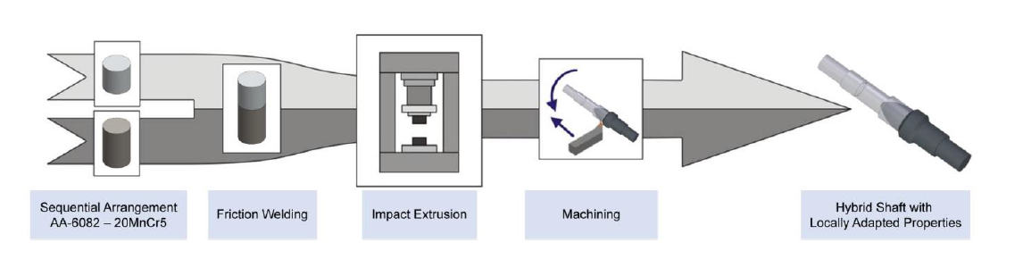 Figure 1: Process chain of the bi-material stepped shaft
The studies classified in the second group involve more complex workpiece preparation methods, usually with a welding, prior to the forming process. Although this ensures better workpiece integrity, the material properties at the joining and heat affected zones are subjected to microstructural changes. Wang et al. [10] studied deformation behavior of bi-material workpieces which are fabricated by weld overlay cladding stainless steel on the circumferential surface of mild steel cylinders. Cladded billets were heated to different warm and hot forging temperatures by using a chamber type furnace and upset by using dies with different surface qualities and lubricating conditions. Cracks were observed at the cladded material after the deformation. Formability, material flow and process load were analyzed analytically and numerically and related to the processing conditions. Domblesky et al. [11,12] utilized friction welding to fabricate hybrid same-metal and bi-metal preforms for forging which consisted of copper, aluminum, carbon steel and stainless steel. They stated that the formability of welded preforms are comparable to that of monolithic preforms at elevated temperatures. Tensile tests applied on the forged copper-carbon steel and carbon steel-stainless steel specimens showed that the fracture occurs at the heat affected zone but not at the welding interface. Regarding the flow behavior during upsetting, they observed a uniform metal flow of same-metal preforms under upsetting due to similar yield strength. However, in bi-metal preforms, deformation was concentrated in the low-strength alloy. A novel processing idea was proposed by Chavdar et al. [13] which is referred to as hot hydroforging. The idea relies on utilizing the hydroforming concept for bulk metal forming by using a bi-material workpiece which consists of a material in the solid state encapsulating another material in the molten state while being forged to a specific form. To obtain the bi-material workpieces, firstly, an aluminum cylinder was placed inside a steel tube and then workpiece ends were sealed by welding steel caps. Utilizing induction heating, the steel was heated above 1000 °C and kept there by manipulating the induction heating generator with on/off cycles until the aluminum melt reached 1000 °C. After forging, a uniform wall thickness of the steel was observed due to hydrostatic pressure acting on the steel wall during forming. However, shrinkage cavities were present in the aluminum due to thermal expansion coefficient (CTE) mismatch between these materials. Glass has been recommended as an alternative core material due to having similar CTE to that of steel. Frischkorn et al. [14] investigated hot forging of welded bi-material workpieces. To fabricate coaxially and sequentially arranged workpieces, deposition welding and friction welding processes were used, respectively. These were isothermally upset at 1200 °C by using a forming simulator. In a follow-up study by Behrens et al. [15], coaxially arranged steel-steel workpieces were formed via cross wedge rolling at 1250 °C. Both studies confirmed that the bi-material workpieces can be hot forged up to high strains without any separation at the joining zone and any damage in either material. However, at a constant temperature, dissimilar flow behavior results in insufficient plastic deformation of the metal with higher flow stress as observed exemplarily in the friction welded 42CrMo4-Inconel 718 combination.
2. Overview of the Tailored Forming Technology
2.1. Process Chain
The investigated product is a bi-material stepped shaft consisting of a wrought aluminum alloy (AA-6082) and a case hardening steel (20MnCr5). Individual processing of these materials is common in the forging industry. The novelty of this work stems from the concept of joining these materials in the first step and processing them further in the joined state. Rod materials with the same diameter will be sequentially joined by friction welding, a solid state welding process. After friction welding, flash around the joining zone will be removed and workpieces will be cut off to the required length. The next step is to produce shaft preforms by metal forming. A single stroke impact extrusion process will be carried out at elevated temperatures to allow for a thermomechanical treatment of the joining zone properties. In the following, the obtained shaft preforms will be machined to the final form and then subjected to heat treatment. A schematic of the process chain is given in Fig. 1.
2.2. Thermal Processing by Induction Heating
At a given temperature, there is a significant difference between the flow behaviors of aluminum alloys and steels. A crucial point of the tailored forming is to obtain a similar flow behavior in the vicinity of the joining zone which makes a tailored temperature distribution over the bi-material workpiece domain essential. This concept can be carried into effect by inductively heating hybrid workpieces prior to the forming process. However, different thermo-magnetic and thermo-physical properties of the two materials make the induction heating a challenging process. For instance, exceeding 550 °C would result in partial melting of the aluminum alloy at the joining zone and thus separation of the sequentially joined materials. In addition, the fact that aluminum has approximately four times higher thermally conductivity compared to steel increases the heat dissipation rate from steel to aluminum alloy which is undesired. Under these challenging circumstances, making use of induction heating simulation in process design is critical. Therefore, numerous heating strategies were evaluated using ELTA™ and Flux™ 2D software prior to experimental implementation.
2.3 Thermomechanical Processing by Impact Extrusion
Impact extrusion is a metal forming process in which a semi-finished workpiece is compressed through an opening in the die in order to obtain a product which has smaller cross sectional area. These are classified according to the direction of the material flow and the geometry of the formed product. The process that is being investigated in this study is referred to as forward rod extrusion.
Forward rod extrusion is essentially a compressive stress dominated metal forming process, although tensile stresses also occur under certain circumstances. In the plastic deformation zone, large displacements at the outer cone lead to dragging of the center in the reverse direction of material flow. Thus, compressive stresses at the center gradually decrease and tensile stresses can be observed. This is especially critical in terms of workpiece integrity while processing joined dissimilar materials. As far as their welding practice is concerned, the joining zone contains some imperfections such as voids. In the presence of tensile stresses, voids existing at the joining zone develop into cracks and propagate. These cracks remain in the microstructure after forming and affect product properties adversely. Even a complete separation of the two materials from each other may take place during deformation. Therefore, the occurrence of tensile stresses should be kept to an admissible level by constructive means. It is believed that good control over the stress state at the joining zone can be achieved by using dedicated tooling with a counter force superposition feature.
A cross sectional view of the designed impact extrusion tooling is shown in Fig. 2. Below the prestressed extrusion die, the back pressure superposition mechanism is situated whose main components are a transverse beam, two heavy duty gas springs and a counter pin. The gas springs are embedded in the base plate to support the transverse beam at both ends. The dimensions of the components have been determined in a way that by the time the joining zone starts entering the die cone, the tip of the extruded section will contact the counter pin and start imposing downward displacements. The downward movement of the counter pin is restricted by the transverse beam due to conical mate at the center. Therefore, the imposed displacements will be transmitted to the gas springs. The resistance of the gas springs to the imposed displacements will generate the required counter force. The magnitude of the counter force can be changed simply by adjusting the filling pressure of the gas springs which provides a simple means to assess the influence of counter force magnitude on the joining zone properties. The maximum counter force that can be achieved by using this setup is approximately 110 kN. Once the deformation stroke is completed, the punch moves back to top dead center and the formed workpiece is released from the die by the built-in ejector of the press.
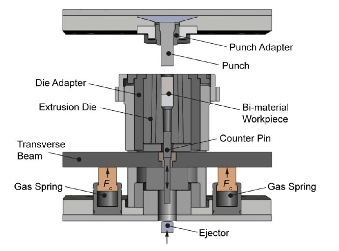 Figure 2: Impact extrusion tooling with counter force superposition feature
The tooling was manufactured, installed in the forging cell and the first strokes were carried out successfully. In Fig. 3, an extruded mono-material preform is shown. The material is 20MnCr5 and has been formed in the warm forging range. A chamber type furnace was used for heating whose temperature was set to 700 °C. Transfer of the workpieces to the extrusion die was carried out manually by using tongs. The extrusion die was preheated to 200 °C by using six cartridge heaters, each being 500 W. These and a K-type thermocouple for temperature monitoring were embedded in the die adapter and connected to closed loop a temperature control unit.
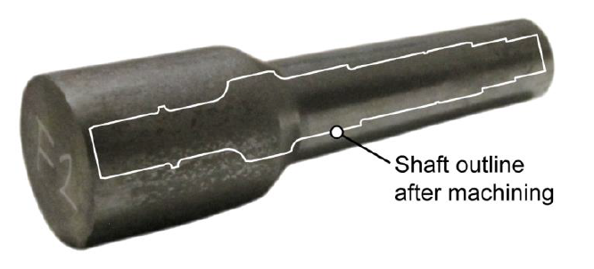 Figure 3: Extruded shaft preform from mono-material
3. Experimental and Numerical Analysis of Induction Heating
3.1. Experimental Setup
Heating and forming experiments will be carried out in a fully-automated forging cell which consists of a screw type press with 5000 kN nominal capacity, an industrial robot and the induction heating rig. Data acquisition equipment is situated by the heating rig to perform in-situ temperature measurements during heating and cooling phases. A toothed belt drive driven by a stepper motor is integrated into the rig to precisely position the workpiece inside the coil and to eject it out after heating. A replaceable ceramic pin is mounted on the belt drive which works in contact with the workpiece.
A mid-frequency generator (Hüttinger TruHeat MF 3040) was used in the heating experiments. Its output voltage was set to 300 V. Maximum power that can be delivered by this generator is 40 kW and the output rate can be adjusted by the user. A water cooled induction coil was mounted to the heating rig which consisted of wound rectangular copper tubing. Wound profile was wrapped with a fire-resistant fabric. A ceramic tube made of mullite was inserted into the coil for centering of the workpiece inside the coil.
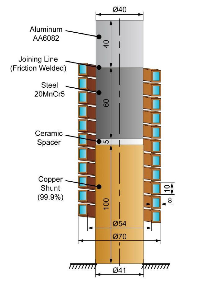 Figure 4: Used experimental setup for induction heating
A schematic of the used experimental setup is shown in Fig. 4. For the sake of clarity, the ceramic tube has been hidden. The bi-material workpiece dimensions and materials’ ratio (60% steel, 40% aluminum) were determined according to the final geometry of the stepped shaft and the process-related requirements (impact extrusion and subsequent machining). The bi-material workpiece has been translated with an axial offset inside the coil for the purpose of developing a temperature profile near to 900 °C in the steel, meanwhile keeping the aluminum as close as possible to room temperature. Therefore, the joining line has been positioned at the height of the coil’s top turn.
Preliminary simulations have shown that the steel end is subjected to overheating due to electromagnetic end effect. This would lead to local melting during heating or an undesired type of metal flow during forming due to considerably low flow stresses of the overheated region. In order to avoid these, a copper cylinder with a slightly larger diameter (Ø41 mm) than that of the workpiece (Ø40 mm) was positioned below the steel and used as a shunt component. A thin ceramic spacer was placed between the copper shunt and the workpiece in order to control the rate of heat extraction from the end of the steel billet. The ceramic ejector which is not shown in Fig. 4 is in contact with the copper’s bottom end and moves the components axially.
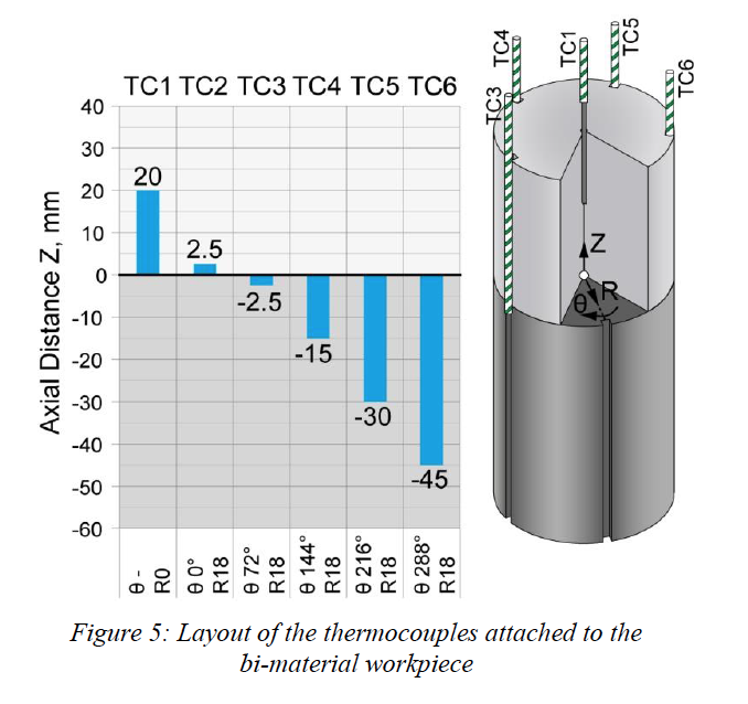 Figure 5: Layout of the thermocouples attached to the bi-material workpiece
Thermocouples (TCs) were used to monitor the evolution of workpiece temperature during and after induction heating. Type-K TCs with thermally insulated cables were selected to survive high temperatures. Sampling rate is equivalent to 2.5 Hz. In Fig. 5, the layout of TCs is shown with respect to a defined polar coordinate system where the origin is set to be the mid-point on the joining line. One TC has been embedded inside the workpiece and five TCs are attached onto the surface at different positions. For surface TCs, five 2 mm depth canals have been cut through with an equiangular spacing of 72°. No significant temperature inhomogeneity in aluminum is expected due to its high thermal conductivity. Therefore, only two TCs have been used for aluminum. TC1 has been embedded into the center at a depth of 20 mm from the top end and TC2 has been attached onto the surface at a distant 2.5 mm from the joining line. In order to capture the temperature gradients on the steel surface, four TC’s have been used. These have been attached to distances of 2.5 mm (TC2), 15 mm (TC3), 30 mm (TC5) and 45 mm (TC6) from the joining line.
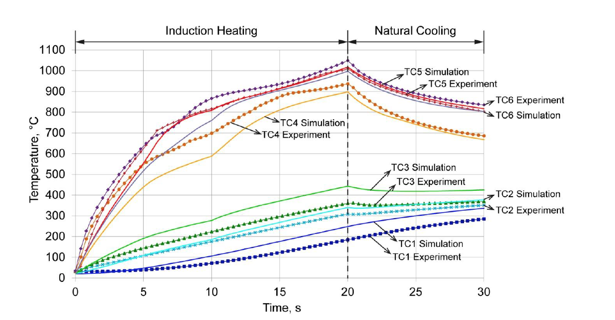 Figure 6: Comparison between experimental temperature readings and simulation results
3.2. Numerical Simulation
An axisymmetric simulation model of the induction heating process has been set up using Flux™ 2D: electromagnetic and thermal analysis software that utilizes the finite element method. Magneto-thermal and thermo-physical properties of the materials have been read from the material library. Ideal thermal and electrical contact has been defined for the interfaces between aluminum-steel, steel-ceramic and ceramic-copper. Between air-aluminum and air-steel, a convection coefficient of 10 W/m2K and an emissivity of 0.7 have been assigned. Applied current has been manipulated to the hold generator output approximately at 25 kW. This value has been chosen considering possible losses in the system and the maximum power that the generator can deliver based on the inductance. Operating frequency has been defined as 15 kHz.
With the aforementioned parameters, steel surface temperature reaches approximately 1000 °C in 20 s. Exceeding this temperature would mean redundant temperature rise in the aluminum and unfavorable material flow during forming. At this instant (t = 20 s), the power is shut down and the analysis continues for another 10 s to observe the evolution of temperature distribution in the workpiece. These phases are referred to as induction heating (t = 0-20 s) and natural cooling (t = 20-30 s), respectively.
4. Results and Discussion
After a series of experiments, it has been found that using 65% of the generator’s capacity, TC5 reads close to 1000 °C after 20 s of heating. This is in accordance with the simulation results. Fig. 6 summarizes the experimental TC readings and simulation results in a single graph. The temperature histories in Flux™ 2D have been extracted from the coordinates corresponding to the TC locations (cf. Fig. 5).
In general, trends are in agreement both in heating and cooling phases. In terms of values, TC5 shows the best agreement. The highest deviations have been observed at TC3 with ΔT being about 80 °C at the end of the heating phase. The minor discrepancies can be attributed to several reasons. First of all, a uniform convection coefficient has been assumed between the bi-material workpiece (both steel and aluminum) and air. However, during heating, the steel side remains inside the coil and the aluminum side is directly exposed to free air. Thus, the assumption of uniform convection coefficient could only be valid up to a certain degree. In addition, emissivity of steel changes remarkably with changing temperature which has not been considered in the calculations.
Although the locations of TC2 and TC3 are close to each other with the joining line in between, the predictions deviate differently from the experimental readings. Here, the ideal contact assumption between the aluminum and steel is questionable. In-depth investigations are necessary to understand the complicated metallurgical nature of the joining interface.
The real contact area between steel-ceramic and ceramic-copper should be far less than the apparent contact area as there was no pressure acting on these components. This makes the ideal contact assumption based on the apparent contact area inaccurate and results in miscalculation of heat conduction between these components. In reality, the heat dissipating to the copper should be less which explains the deviation in TC6.
The heated workpiece will be transferred to the forming die by an industrial robot. The anticipated time between the end of heating and the onset of deformation is about 5 s. Interpreting the heat dissipation phenomenon during the transfer phase is essential as it dictates the initial temperature distribution before forming. Contoured temperature distributions as well as temperature profiles of the center and the surface are shown in Fig. 7 after heating (t = 20 s) and before forming (t = 25 s).
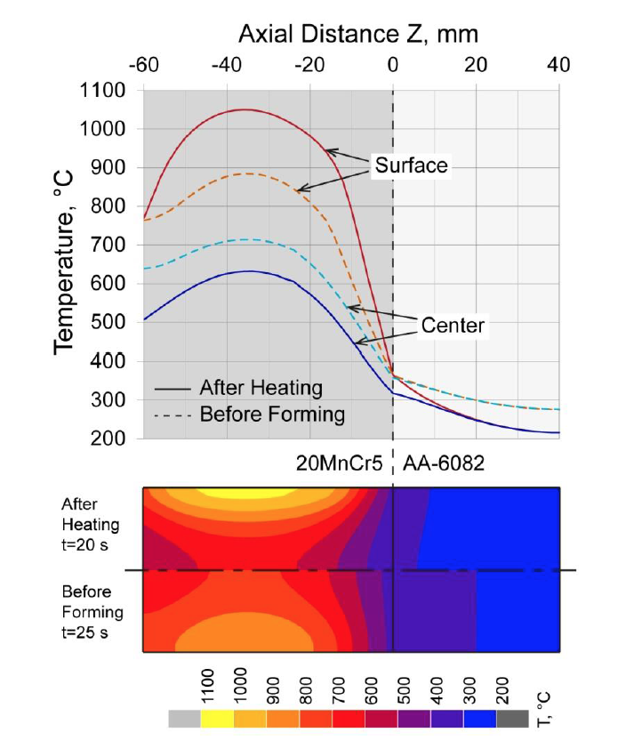 Figure 7: Temperature distributions of the bi-material workpiece after heating and before forming
During the transfer, the joining line temperature at the surface remains stable at 365 °C, but an increase from 318 °C to 358 °C has been observed at the center. In comparison to steel, temperature distribution in aluminum is more homogeneous due to its relatively high thermal conductivity. After 5 seconds of natural cooling, the surface and center temperatures balance out. In spite of that, a thorough temperature distribution cannot be obtained in steel. The maximum difference between the surface and center has been found to be 170 °C at an axial distance of -35 mm. It should be emphasized that only a 10 mm portion (-10
5. Conclusion and Outlook
This study has presented the tailored forming technology with an exemplary product: a bi-material stepped shaft. The workpieces have been produced by friction welding aluminum (AA-6082) and steel (20MnCr5) billets which is the initial step in the process chain. The requirements for thermal and thermomechanical processing of bi-material workpieces have been manifested. Preliminary studies have shown that a successful forming operation requires a non-homogeneous temperature distribution in the workpiece. Induction is a suitable thermal process for this purpose, although some complex phenomena, such as different thermo-magnetic and thermo-physical properties of the materials and the forming-related restrictions, make it challenging. In order for a good understanding and an appropriate thermal process design, modeling and experimentation of induction heating of bi-material workpieces have been carried out. Based on the modeling results, an experimental setup has been built and the calculations have been validated.
Due to timing constraints, the thermal process design was limited to tools currently available at IFUM. Calculations have already been made for the use of an improved induction coil using Fluxtrol magnetic flux controllers along with different cooling during heating concepts. The direction of these concepts is to lower the aluminum temperatures, reduce the transient zone between steel and aluminum and reduce the radial gradients in the steel. One promising concept involves the use of submerged heating. Additional publications on these concepts and their realization will be published in the future.
Further study will focus on extending the modeling capabilities. Forming simulation will be incorporated by using Marc™ software. The temperature distributions calculated by Flux™ 2D will be transferred to Marc™ as initial temperature condition for forming. To this end, a user subroutine has already been written and tested. A comprehensive material characterization study to obtain material flow curves for a broad temperature range and to determine joining zone properties is in progress.
Some preliminary forming simulations have shown that the temperature distribution before forming is maintained up to a great extent during forming because of the fast press speed. Heat losses are almost negligible and some amount of heat input is due to deformation heating. However, as heat dissipation from steel to aluminum will proceed until complete balancing, attention has to be paid that the joining zone temperatures remain under the melting point of aluminum. A post forming controlled cooling may be necessary to remove excessive heat from aluminum.
It is also understood that for this type of component, post forming selective heat treatment will likely be required. 20MnCr5 is a case hardening steel, which requires the addition of carbon via diffusion in order to achieve significant strength improvements. After joining to the aluminum, it will not be possible to perform traditional carburizing technology to this component, because the processing temperature exceeds the melting temperature of aluminum. Post forming heat treating on this steel could be achieved using the technology invented by Prof. Saveliy Gugel for submerged inductive hardening in a liquid active media [16]. In this technology, the component is submerged in a carbon rich liquid. Inductive heating is used selectively on the component to boil and then form a carbon rich vapor blanket over the region of the component that hardening is desired on. In adjacent aluminum regions, the cooling capacity of the liquid will be sufficient to prevent overheating of this region while the carbon is diffusing in the steel. After sufficient time, the power is turned off, the vapor blanket collapses and the liquid media quenches the treated region of the component to form a locally case hardened layer.
An alternative solution could be to use an induction hardenable steel prior to welding and forming. Due to the lower alloy content, the weldability of these steels tends to be better than case hardening steels and the price of the steel tends to be lower. Also, their hardenability tends to be much less, so a more rapid rate of heat extraction after the forming process would be possible. Additional modelling should be made on the complete manufacturing chain for alternative steel and aluminum alloy types to determine the best material combination for this application.
Acknowledgments
The results presented in this paper were obtained within the Collaborative Research Centre 1153 ‘‘Process chain to produce hybrid high performance components by Tailored Forming’’ in the subproject B3. The authors would like to thank the German Research Foundation (DFG) for the financial and organizational support of this project. The authors would also like to provide thanks to Fluxtrol for providing institutional support for the project.
References
[1] Merklein, M. et al., “A review on tailored blanks – Production, applications and evaluation”, Journal of Materials Processing Technology, 214–2, (2014), pp. 151–164.
[2] Mori, K. et al.,“Joining by plastic deformation”, CIRP Annals – Manufacturing Technology, 62–2, (2013), pp. 673-694.
[3] Groche, P. et al., “Joining by forming–A review on joint mechanisms, applications and future trends”Journal of Materials Processing Technology, 214–10, (2014), pp. 1972-1994.
[4] Wagener, H.W. and Haats, J., “Pressure welding of corrosion resistant metals by cold extrusion”, Journal of Materials Processing Technology, 45–1, (1994), pp. 275-280.
[5] Kazanowski, P. et al., “Bi-metal rod extrusion–process and product optimization”, Materials Science and Engineering: A,369–1–2, (2004), pp. 170-180.
[6] Rhee, K.Y. et al., “Fabrication of aluminum/copper clad composite using hot hydrostatic extrusion process and its material characteristics”, Materials Science and Engineering: A, 384–1–2, (2004), pp. 70–76.
[7] Schlemmer, K.L. and Osman, F.H., “Differential heating forming of solid and bi-metallic hollow parts”, Journal of Materials Processing Technology, 162–163, (2005), pp. 564-569.
[8] Behrens, B.–A. et al., “Investigation of load adapted gears and shafts manufactured by compound–forging”, Journal of Advanced Manufacturing Systems, 7–1, (2008), pp. 175–182.
[9] Essa, K. et al., “Upsetting of bi-metallic ring billets”, Journal of Materials Processing Technology, 212–4, (2012), pp. 817-824.
[10] Wang, J. et al., “Study of the hot forging of weld cladded work pieces using upsetting tests”, Journal of Materials Processing Technology, 214–2, (2014), pp. 365–379.
[11] Domblesky, J. and Kraft, F., “Investigation of Welded Preforms for Use in Forging” SAE Technical Paper, 2005–01–3287, (2005).
[12] Domblesky, J. et al., “Welded preforms for forging”, Journal of Materials Processing Technology, 171–1, (2006), pp. 141–149.
[13] Chavdar, B. et al., “Hot Hydroforging for Lightweighting”, 5th International Conference on Distortion Engineering, Bremen, Germany, September 2015.
[14] Frischkorn, C. et al., “Investigation on a new process chain of deposition or friction welding and subsequent hot forging”, Materialwissenschaft und Werkstofftechnik, 44, (2013), pp. 783–789.
[15] Behrens, B.–A. et al., “Basic study on the process combination of deposition welding and subsequent hot bulk forming”, Production Engineering, 7–6, (2013),pp. 585–591.
[16] Gugel, S.M., “Induction Carburizing - A Novel Cost Effective Environmentally Safe, Affordable Technology”, Phase II, Contract No. N00014-00-C-0560, “Furnish the necessary personnel and facilities to conduct research of the optimum treatment parameters of new Induction Carburizing Technology (LINCARBTM) in liquid active media (LAM) for special gears”, Final Technical Report No. N14-03/3, 06/30/2004, pp. 1-389.
If you have more questions, require service or just need general information, we are here to help.
Our knowledgeable Customer Service team is available during business hours to answer your questions in regard to Fluxtrol product, pricing, ordering and other information. If you have technical questions about induction heating, material properties, our engineering and educational services, please contact our experts by phone, e-mail or mail.
Fluxtrol Inc.
1388 Atlantic Boulevard,
Auburn Hills, MI 48326
Telephone: +1-800-224-5522
Outside USA: 1-248-393-2000
FAX: +1-248-393-0277