Toll Free


Information
Authors: Lee M. Rothleutner, Chester J. Van Tyne, Robert Goldstein, John Jackowski, and Greg Fett
Location/Venue: HT 2017
Download Full Paper
Download Presentation
Abstract
Vanadium microalloying additions are common in medium carbon ferrite-pearlite steel shafts. The increased load capacity provided by vanadium carbonitride precipitation is beneficial in many applications. Induction hardening can further increase the surface strength of a component; however, the implications of the vanadium carbonitride precipitates on microstructural evolution during induction hardening are unclear. Evidence that vanadium microalloying influences the microstructural evolution of the induction hardened case as well as the case/core transition regions are presented in the current study. Vanadium increases the amount of non-martensitic transformation products in the case while decreasing austenite formation kinetics in the case/core transition region. Observations in induction-hardened shafts were supported by Gleeble® physical simulations of computer simulated thermal profiles. Characterization was conducted using scanning electron microscopy, dilatometry, and microhardness testing.
Introduction
Three distinct microstructural regions are seen in the cross-section of an induction-hardened shaft: case, core, and case/core transition. Figure 1 shows an example macrophotograph of an induction-hardened shaft indicating the case, core, and case/core transition regions. The case region is fully martensitic (ideally); however, retained austenite on the order of a couple percent can be expected in the 0.40 to 0.60 wt.% carbon (C) range[1]. The microstructure of the case/core transition region can consist of a broad range of constituents depending on the processing parameters, exact radial location, core (i.e., prior or starting) microstructure, and alloy content.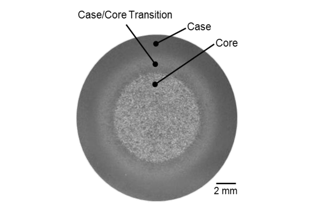 Figure 1: Macro-etched cross-section showing the microstructural regions of an induction-hardened shaft. Macrograph is from the present study.
For a ferrite-pearlite core microstructure, typical of induction hardened vanadium microalloyed medium-carbon steels [2], the transition region can be a mix of martensite, bainite, partially transformed pearlite, and retained ferrite. Improper selection of processing parameters can result in undissolved carbides and retained ferrite in the case, which can lead to detrimental properties.
Understanding Thermal History in Induction Hardening
Induction hardening generates large internal thermal gradients that are extremely difficult to measure. As a result, thermal profiles are often modeled using computer simulations instead of measured directly using imbedded thermocouples. Figure 2 shows predicted induction hardening thermal profiles at different depths in a 35mm diameter bar of steel. Three regions can be identified in the near surface thermal profiles: heating, dwell (often very short), and quench [3].
After heating to a target peak temperature, a dwell period can be used to provide additional austenitizing time to dissolve alloy carbides and nitrides as well as to allow heat to diffuse into the bar, increasing case depth [4]. Figure 2 shows a decrease in temperature during the dwell stage, which is due to radiative heat loss at the surface and conductive heat loss into the shaft. As the distance from the surface increases, changes in heating rate, peak temperature, and time above critical temperatures (Ac1 and Ac3) vary greatly and result in a significant microstructural gradient upon quenching.
Figure 3 shows the influence of heating rate on the homogeneity of austenite from a ferrite-pearlite Ck45 steel. The Ac3 temperature increases more than the Ac1 as the heating rate increases. Approximate combinations of heating rate and peak temperature for the case and case/core transition regions are indicated.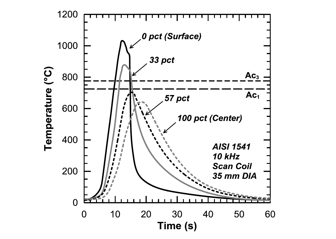 Figure 2: Predicted induction hardening thermal gradients generated using magneto-thermal modeling. Plot adapted from Li et al. [3].
  Figure 3: Austenite transformation behavior of a ferritepearlite Ck45 steel as a function of heating rate. Adapted from Orlich et al. [5].
In general, induction hardening results in either inhomogeneous austenite or a mixture of ferrite, pearlite, and austenite before quenching. Inhomogeneous austenite consists of significant compositional gradients as well as undissolved alloy carbides, both of which can result in significant differences in local hardenability. For example, if just carbon compositional gradients from 0.10 to 0.80 wt.%C are considered for a plain medium-carbon steel, the critical cooling rate from Ac3 to create a fully martensitic microstructure varies from 411 to 16°C/s, respectively [6].
Variation in the carbon content of the martensite in the case, along with very fine austenite grain size, is one explanation for a phenomenon sometimes seen in induction-hardened components called “superhardness” [7]. Superhardness is defined as an increase in surface hardness of 2-4 HRC above the expected martensite hardness levels observed during furnace hardening. Some studies argue the superhardness phenomenon is not a result of inhomogeneous martensite, but instead is a result of the high cooling rate of the thin induction-heated layers and is independent of heating rate [8]. Refining the austenite grain size from ASTM 7 to 14 was found to enhance the proposed superhardness effect by an additional 2 HRC [9].
Depending on the specific alloy composition, heating rate, peak temperature, time at peak temperature, and cooling rate, a microalloying element can exist in a variety of different forms simultaneously. Whether the microalloying element is residing in solid solution, precipitating, coarsening, or dissolving, it can directly impact both subsequent phase transformations as well as the precipitation strengthening response. Consequently, characterizing and understanding precipitate dissolution during induction hardening is essential to understanding the effect of a specific microalloying element.
Dissolution of Precipitates
The dissolution kinetics of precipitates were first described by Aaron [10] for the one-dimensional diffusion controlled dissolution of planar precipitates. Whelan [11] extended this analysis to the three-dimensional dissolution of spherical precipitates, which is more applicable to microalloyed steels. Figure 4 shows schematically the concentration profiles of the rate limiting species as a function of time for a dissolving precipitate. The mathematical model assumes a stationary interface between the precipitate and the matrix; therefore, concentration Cm represents a local equilibrium condition that can be approximated using a solubility product.
Aaron and Kotler extended the relationship developed by Whelan to account for curvature effects on both spherical and planar precipitates [12]. A modified Gibbs-Thompson equation was used to describe the composition of the matrix and the precipitate/matrix interface as a function of precipitate radius.
Figure 5 schematically shows the effect of curvature on precipitate dissolution rate. The dissolution rate of planar and spherical precipitates is identical and very high during the early stages of dissolution. The rate decreases markedly due to the change in the concentration gradient from an initial “infinite” value.
The planar and spherical precipitate dissolution rates diverge after some time, with the dissolution rate of the planar precipitate continuing to decrease while the spherical precipitate increases significantly due to the Gibbs-Thompson effect. Dissolution of precipitates in microalloyed steels, having a fine precipitate size, is likely highly influenced by curvature effects.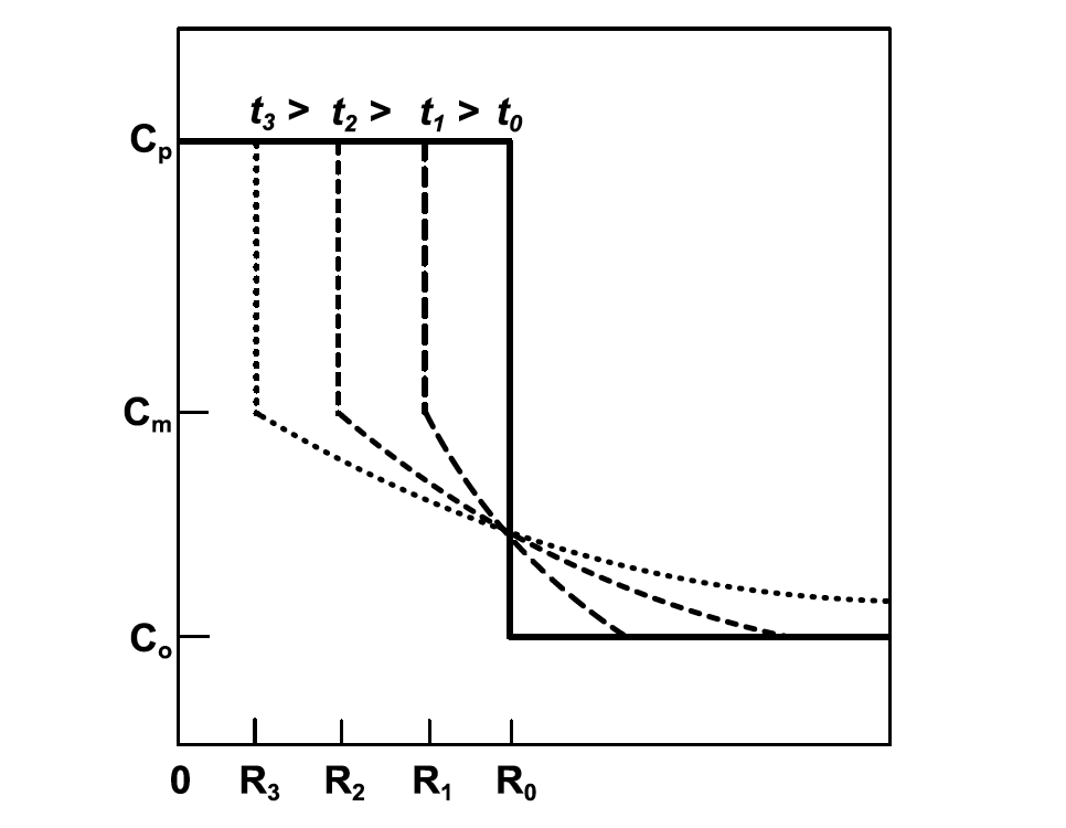 Figure 4: Schematic of solute concentration profiles of a dissolving precipitate as a function of time. Adapted from Whelan [11].
 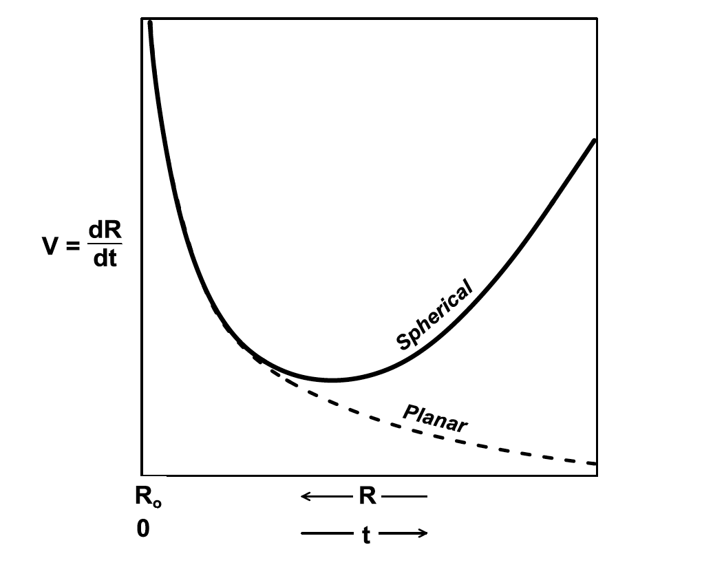 Figure 5: Schematic of dissolution velocity for spherical and planar precipitates as a function of size and elapsed time. Adapted from Aaron and Kotler [13].
Influence of Vanadium Microalloying
In a study by Rivas et al. [14-16] a vanadium (V) microalloyed medium-carbon steel (0.11 wt.% V and 0.30 wt.% C) was forged at 1315°C, cooled to room temperature, and induction hardened. Figure 6 shows the results of carbon extraction replicas taken at different depths in the component. Even though case depth was not reported, the two measurements closest to the surface were indicated as being within the case region and the sampling depth furthest into the forging was the core.
The average particle diameter was observed to increase from 7nm near the core to 12.6nm near the surface. Even though the overall increase in the average particle diameter from core to surface is not statistically significant, Rivas et al. indicated that there was evidence of dissolution and reprecipitation of the finer carbides. Law and Edmonds found that fine vanadium carbides can dissolve below their equilibrium solubility temperature by as much as 220°C [17]. The same study showed 2nm thick VC 0.75 dissolved in only 15s at 900°C. Since diffusional processes are much more sensitive to temperature than time at temperature, this has significant implications during induction hardening at peak temperatures in excess of 1000°C.
The mechanism for the dissolution of VC 0.75 at much lower temperatures and times than anticipated is due to a very specific series of events. First, the VC 0.75 originally precipitated in ferrite. Upon heating, the ferrite transforms to austenite and a sudden increase in interfacial energy occurs due to the precipitate coming into contact with a face-centered cubic structure instead of a body-centered cubic structure [18]. The increase in interfacial energy accelerates the reversion kinetics of the VC 0.75. Figure 6: Vanadium carbide precipitate diameter as a function of depth from the surface of an induction-hardened forging. Error bars are plus/minus one standard deviation. Adapted from Rivas et al. [14].
Although microalloying additions undoubtedly increase properties such as strength and fatigue performance, they can also adversely influence phase transformation behavior through an effect on hardenability. A smaller austenite grain size has been shown to markedly, and negatively, influence hardenability (i.e., Jominy hardenability) in plain carbon steels [19]. However, the influence of microalloy elements such as V and niobium (Nb) is not as straightforward as a simplistic austenite grain refinement mechanism. Depending on the alloy composition and the austenitizing temperature, microalloying elements may be in solution, precipitating from austenite, or both, all of which can impact hardenability differently.
Figure 7 shows the influence of vanadium on hardenability as a function of reheat temperature from Grossmann [19] as well as data currently used in the ASTM International standard for determining the hardenability of steels [20]. Although the current ASTM standard shows no dependence of reheat temperature on vanadium’s hardenability effect, Grossmann showed a clear effect in data from 1952. At low V levels, VC can readily go into solid solution, even at low reheat temperatures, and can have a very large impact on hardenability. As V content increases, higher reheat temperatures are required to get the V into solid solution [19]. Figure 7: Multiplying factors for calculating the effect of vanadium on the hardenability of steel. Adapted from Grossman [19] and ASTM-A255 [20].
The mechanism for the influence of microalloying additions on hardenability has been examined further since Grossmann [21-24]. With vanadium microalloying additions, a grain boundary pinning mechanism was introduced by Garbarz and Pickering [21, 22] and later supported by Adrian [23] as well as Adrian and Staśko [24]. Garbarz and Pickering found that if austenite grain boundaries are not inhibited, the boundary moves too quickly for segregation to occur, thereby decreasing hardenability. However, hardenability is enhanced if austenite grain boundaries are inhibited by undissolved carbonitrides, allowing V to segregate to the grain boundaries, decreasing boundary surface energy and inhibiting the diffusional transformation of austenite. Nucleation of non-martensitic transformation products may be favorable when carbonitrides coarsen and are no longer effective at inhibiting grain growth.
Experimental Procedures
Specific locations within an induction hardened shaft were modeled and physically simulated using a Gleeble® 3500. Two grades of 1045 steel and three different induction hardened conditions were simulated. Microstructural and hardness data were collected for analysis.
Materials
The two alloys used in this research, 1045 and 10V45, have been previously presented by Rothleutner et al. [25] and are discussed here in brevity for completeness. Table 1 shows the nominal chemical composition for both alloys. Microstructures are ferrite-pearlite with the 10V45 having an appreciably smaller ferrite grain size and ferrite fraction. The 1045 has 16.9±2.0% ferrite with a ferrite grain size of 6.4±3.9μm, while the 10V45 has 13.5±1.5% ferrite with a ferrite grain size of 3.3±2.8μm.
These microstructural differences, in addition to the vanadium addition to the 10V45, lead to significant hardness differences: 217±5HV 1kg for the 1045 and 281±9HV 1kg for the 10V45. Figure 8 shows representative secondary electron SEM images of the two materials in the hot-rolled condition taken transverse to the rolling direction.
Table I: Chemical Composition of Materials in wt.%
| Steel | C | Mn | Si | Ni | Cr | Mo |
|---|---|---|---|---|---|---|
| 1045 | 0.44 | 0.74 | 0.23 | 0.10 | 0.12 | 0.03 |
| 10V45 | 0.47 | 0.82 | 0.28 | 0.09 | 0.12 | 0.03 |
| Steel | V | Al | N | S | P | Cu |
| 1045 | 0.002 | 0.016 | 0.0068 | 0.006 | 0.010 | 0.26 |
| 10V45 | 0.080 | 0.007 | 0.0100 | 0.009 | 0.007 | 0.22 |
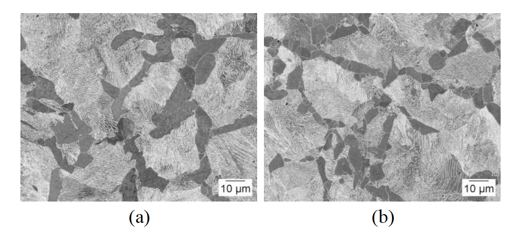 Figure 8: Representative secondary electron SEM images of as-hot rolled (a) 1045 and (b) 10V45 steels.
Induction Hardening
Hot rolled specimens approx. 15mm in diameter (see Rothleutner et. al [25] for specimen details) were scan induction hardened to nominal normalized effective case depths (t/r) of 0.25 (25%) and 0.44 (44%) using 72kW of power at 196kHz, designated Low and High, respectively. The High condition was made by simply using a 25% slower scan speed (17.3mm/s) than the Low condition (22.9mm/s). The High condition nominal normalized effective case depth also was replicated using a single-shot induction hardening setup, and designated High-SS. The High-SS condition was made using 128kW of power at 30kHz. Figure 9 shows representative transverse macrographs of the three conditions.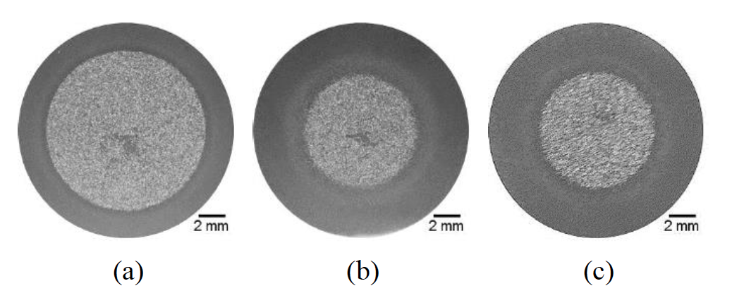 Figure 9: Macrographs of 1045 steel in the (a) Low (25%), (b) High (44%), and High-SS (44%) induction hardened conditions.
Computer Modeling of Thermal Process
The surface and total case depth locations for the Low, High, and High-SS conditions were modeled using one- and two-dimensional magneto-thermal modeling software packages—ELTA and Flux 2D respectively. ELTA was used in the analysis of the High-SS condition while Flux 2D was used for the Low and High conditions. Induction hardening parameters, coil design, and specimen geometry were all incorporated into the models. Table 2 shows the locations in the induction hardened torsional fatigue specimens for each condition modeled as well as the software package used.
Table II: Induction Hardened Conditions Modeled
| Condition | Software | Location Description | Distance from Surface (mm) |
|---|---|---|---|
| Low | Flux 2D | Surface Total Case Depth | 0.00 2.10 |
| High | Flux 2D | Surface Total Case Depth | 0.00 3.80 |
| High-SS | ELTA | Surface Total Case Depth | 0.00 3.80 |
Figure 10 shows the surface thermal profiles obtained from modeling for the Low, High, and High-SS conditions. Surface profiles show the heating rate is very similar between the conditions, but peak temperature and cooling behavior differ. Of particular significance is the duration in which the High condition is in the austenite phase field (approx. >770°C). This duration is more than twice as long as in any other condition.
Figure 11 shows the modeled thermal profiles for the Low, High, and High-SS conditions at their respective total case depths. Total case depth profiles show that the three conditions have nearly identical peak temperatures with varying times for both peak temperature and cooling behavior. The High condition is at peak temperature much longer than the other two conditions.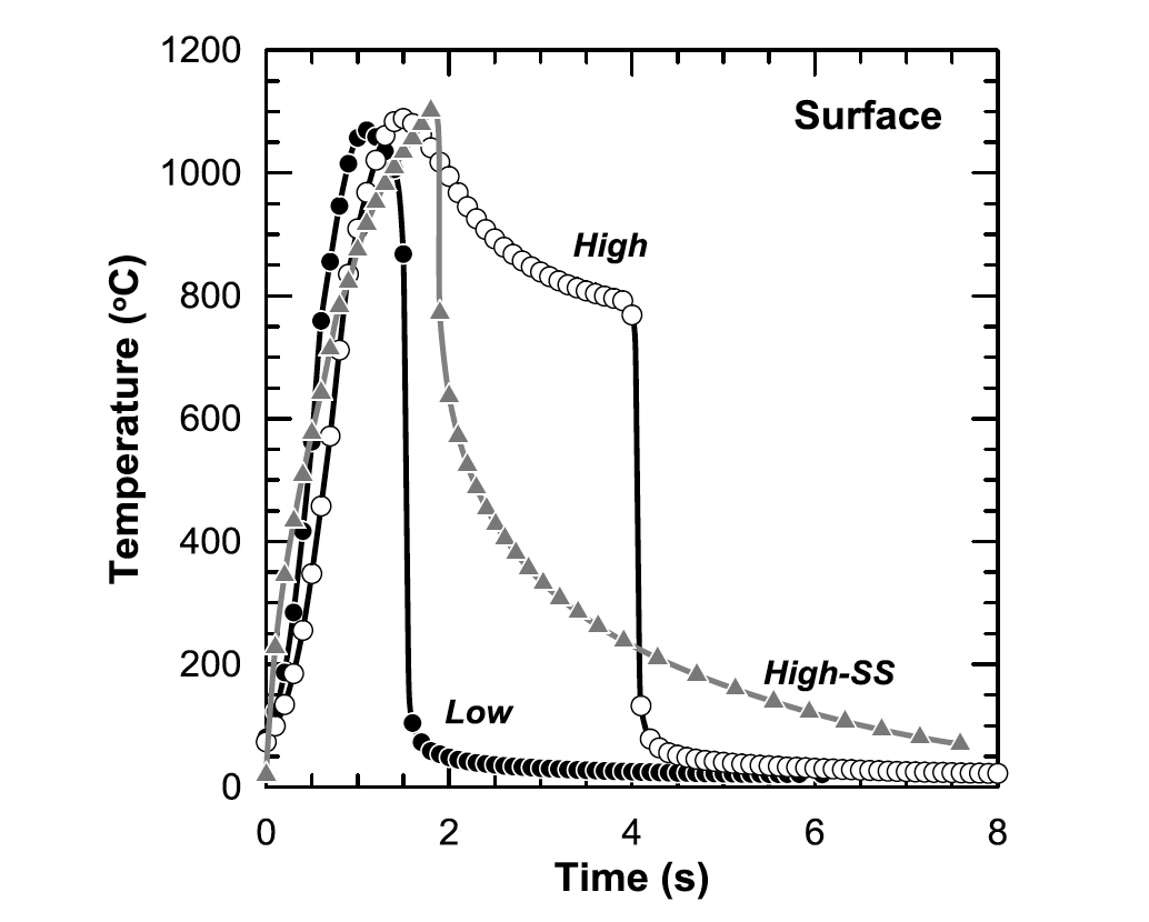 Figure 10: Surface thermal profiles for the Low, High, and High-SS conditions obtained from modeling.
 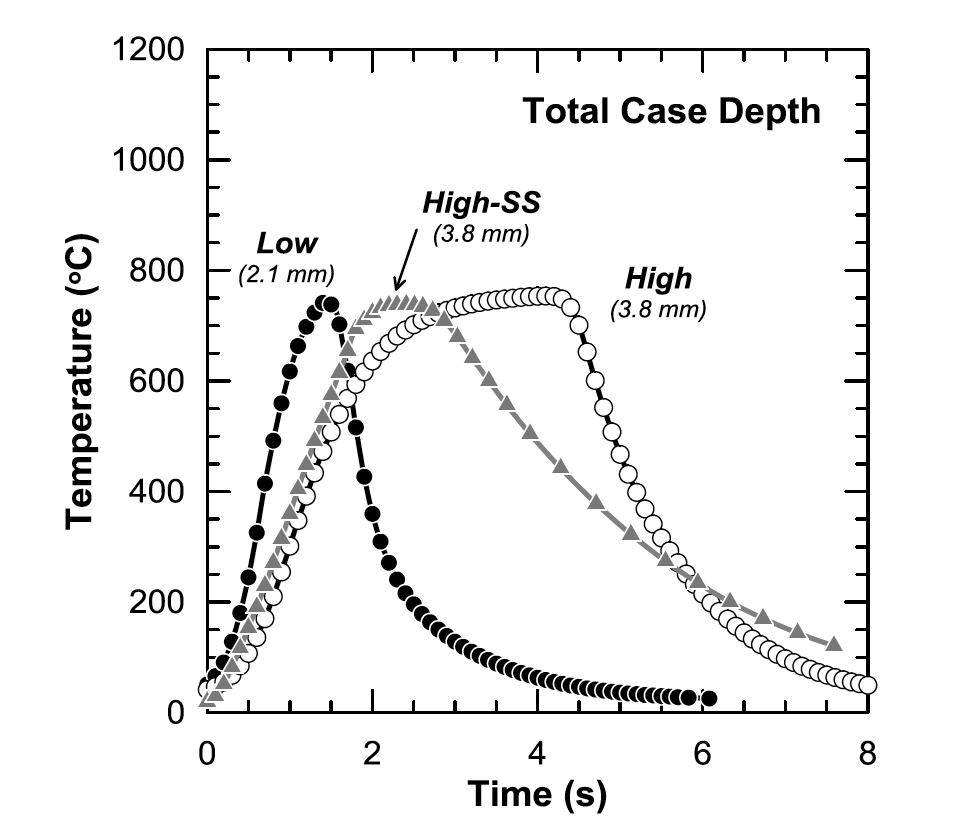 Figure 11: Total case depth thermal profiles for the Low, High, and High-SS conditions obtained from magneto-thermal modeling.
Gleeble® Physical Simulations
Thermal gradients determined via modeling for both the surface and the total case depth of all induction hardened conditions were simulated using a Gleeble® 3500. The ISO-Q® specimen design was selected for this study because it has high heating and cooling rates capability while allowing dilatometry data to be collected. Figure 12 shows a detailed drawing of the ISO-Q® specimen.
The specimen was held in the Gleeble® low-force fixturing using copper hot-grips specifically designed to reduce physical contact with the specimen which reduces longitudinal thermal gradients. Nozzles were inserted into the tubular ends to quench the specimen internally with either nitrogen gas or water, depending on the desired cooling rate. Diametrical dilation data were collected via a quartz push-rod LVDT dilatometer.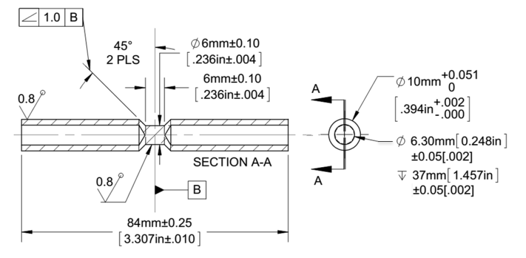 Figure 12: Schematic of ISO-Q® specimen used in Gleeble® physical simulations.
Results and Discussion
Induction Hardened Case Microstructure
In the current study, the induction hardening cycles were very rapid. Calculated peak surface temperatures of 1070, 1089, and 1100°C were achieved in 1.0, 1.5, and 1.8s for the Low, High, and High-SS induction hardened conditions, respectively. Figure 13 shows representative secondary electron SEM images of the martensitic case microstructure of the 10V45 steel in the Low and High case depth conditions. The High condition does appear to have a coarser martensitic structure due to the longer austenitizing time, which resulted from the slower scan speed needed to achieve the high case depth.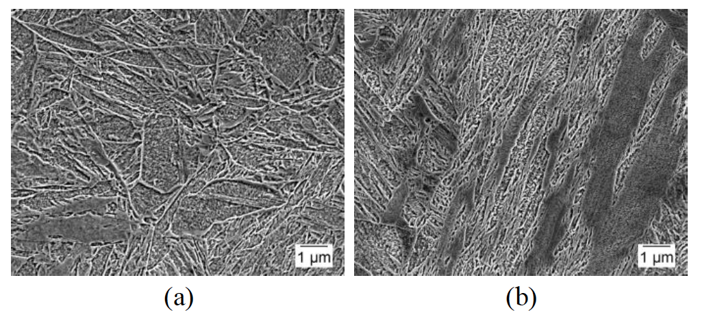 Figure 13: Representative secondary electron SEM images of the martensitic case microstructure of 10V45 (a) Low and (b) High conditions. (2% nital etch.)
Even though the calculated surface temperatures were very high, the 10V45 conditions exhibited a very small fraction of non-martensitic transformation products (NMTP) in the case. Figure 14 shows an SEM micrograph at the surface of an induction hardened torsional fatigue specimen of 10V45 in the High-SS condition with a region of non-martensitic transformation product. Interestingly, the case hardness was not affected by the existence of the non-martensitic transformation products. This result is likely because the very small fraction of NMTP present in the microstructure was not resolvable with microhardness testing, and was simply a contribution to the variability of hardness data in the case region.
The observation of NMTP at the induction-hardened surface suggests that either the modeling is inaccurate or there is a V effect on hardenability. Although the induction hardening simulations were not validated for the current study by induction hardening instrumented specimens, visual confirmation of the surface temperatures during specimen processing was determined to be reasonable. Fett and Held [2] reported that vanadium microalloyed steels have been observed to exhibit “inferior” induction hardened case microstructures when compared to plain carbon steels; however, no mechanism was proposed.
Vanadium precipitates along austenite grain boundaries have been shown to promote ferrite nucleation in low-carbon steels [26]. This mechanism may provide evidence for the formation of NMTP in medium-carbon steels as well, indicating that V reduces the hardenability of medium-carbon steels by promoting ferrite formation. Approximating the dissolution kinetics of V precipitate in the 10V45 steel can give weight to this hypothesis. Figure 14: Representative secondary electron SEM image and associated schematic of a 10V45 High-SS specimen showing regions of non-martensitic transformation products in the case region adjacent to the surface. (2% nital etch.)
Figure 15 shows isothermal dissolution kinetics for 3 to 6nm diameter precipitates of vanadium carbide (VC 0.75) at 1000 and 1070°C determined using equations from Whelan [11]. Only VC 0.75 is shown because of its significantly higher solubility compared to vanadium nitride (VN) in both ferrite and austenite. Therefore, VC 0.75 represents the upper bound for dissolution kinetics in the 10V45 steel.
The dissolution temperature of 1000°C corresponds to the minimum recommended induction hardening temperature for a 0.45 wt.% C steel containing strong carbide formers (i.e., V) [28]. The dissolution temperature of 1070°C corresponds to the calculated peak temperature for the Low induction hardened condition in the current study. At 1000°C, VC 0.75 precipitates dissolve rapidly, going in to solution in 2 to 6s. Given the extremely fine size of the precipitates, the dissolution time may be even less due to the Gibbs-Thompson effect previously discussed.
In the current study, the longest calculated heating time to peak temperature was 1.8s, with the maximum time >800°C being approx. 4s, suggesting the vanadium is likely still primarily in precipitate form during the induction hardening cycle in the case — and, therefore, throughout the component as well. Rivas et al. [14-16] have examined the evolution of VC precipitate size distributions of approximately the same initial size during induction hardening. Rivas et al. suggest VC precipitate size actually increases in the induction hardened case region, but the statistical significance of this observation was inconclusive. The coarsening of the VC precipitates was attributed to the relatively slow heating rate to the peak temperature used in their study: 22s to 1040°C.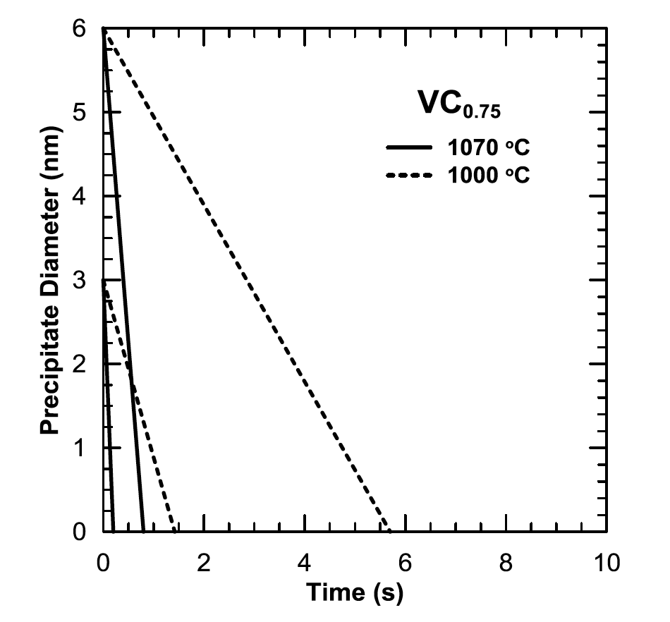 Figure 15: Calculated isothermal dissolution kinetics of VC0.75 at 1000 and 1070 °C for both 3 and 6 nm precipitates. Calculations made using equations from Whelan [11] and solubility product data from Turkdogan [27].
Simulation of Induction Hardening
The surface and total case depth of the Low, High, and High-SS conditions were simulated using a magneto-thermal finite difference or finite element analysis software and then physically simulated for analysis via dilatometry, hardness, and microscopy methods.
Figures 16 and 17 show the microhardness results for the surface and total case depths of both steels in all conditions, respectively. In general, all conditions exhibited consistent hardness levels in both the surface and total case depth simulations for a given steel, except the total case depth simulation in the High condition, which had much higher hardness than its 10V45 counterpart. The simulated surface of the 10V45 steel exhibited a higher hardness than the 1045, but since the 10V45 contained slightly higher carbon content, no clear vanadium influence can be determined. Figure 16: Vickers microhardness results for 1045 and 10V45 steels from the simulated surface thermal histories for Low, High, and High-SS conditions. Error bars indicate the 95% confidence interval of the mean hardness.
Figures 18 and 19 show SEM images of the 1045 and 10V45 steels from the total case depth simulation of the High condition. Regions of martensite are highlighted in the 1045 with an “M” and circled in the 10V45 microstructures. The 1045 steel exhibited a significantly higher volume fraction of martensite (13.5±0.6%) as compared to the 10V45 steel (1.1±0.5%). The difference in austenitizing behavior between the two steels was repeated and microstructural observations were corroborated with dilatometry.
Figures 20 and 21 show dilatometry curves for the total case depth simulation in the High condition for both the 1045 and 10V45 steels, respectively. Distinct differences between the two steels were observed both at peak temperature and between 200 and 300°C. These results indicate more austenite formed in the 1045, seen as a larger reduction in strain during the high temperature hold, which resulted in more martensite forming during quench. This indication was further supported by the 1045 steel exhibiting a distinct martensite start temperature upon cooling, which is not seen in the 10V45.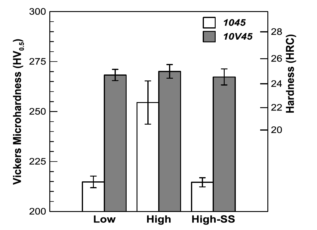 Figure 17: Vickers microhardness results for 1045 and 10V45 steels from the simulated total case depth thermal histories for Low, High, and High-SS conditions. Error bars indicate the 95% confidence interval of the mean hardness.
 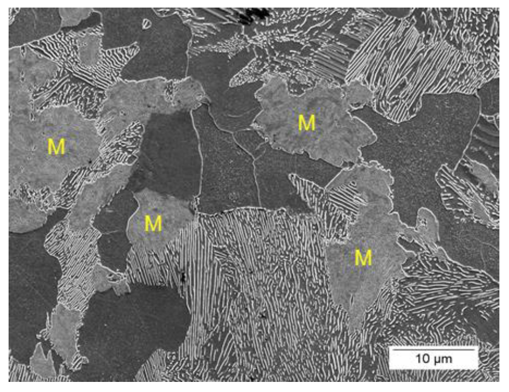 Figure 18: Representative secondary electron SEM image of the simulated total case depth in the 1045 High condition. Largest regions of martensite are indicated with an “M.” (2% nital etch.)
The reduced austenite formation in the 10V45 steel at the simulated total case depth in the High condition is consistent with observations made by Fett and Held [2] on induction hardened medium-carbon steels. Fett and Held found that both V and Nb microalloying reduced the depth to 40 HRC, with niobium causing the greatest reduction. These results suggests that the mechanism reducing austenite formation is closely related to microalloy precipitates either reducing austenite nucleation rate at low austenitizing temperatures or inhibiting austenite grain growth. Evidence favoring one mechanism over the other is inconclusive.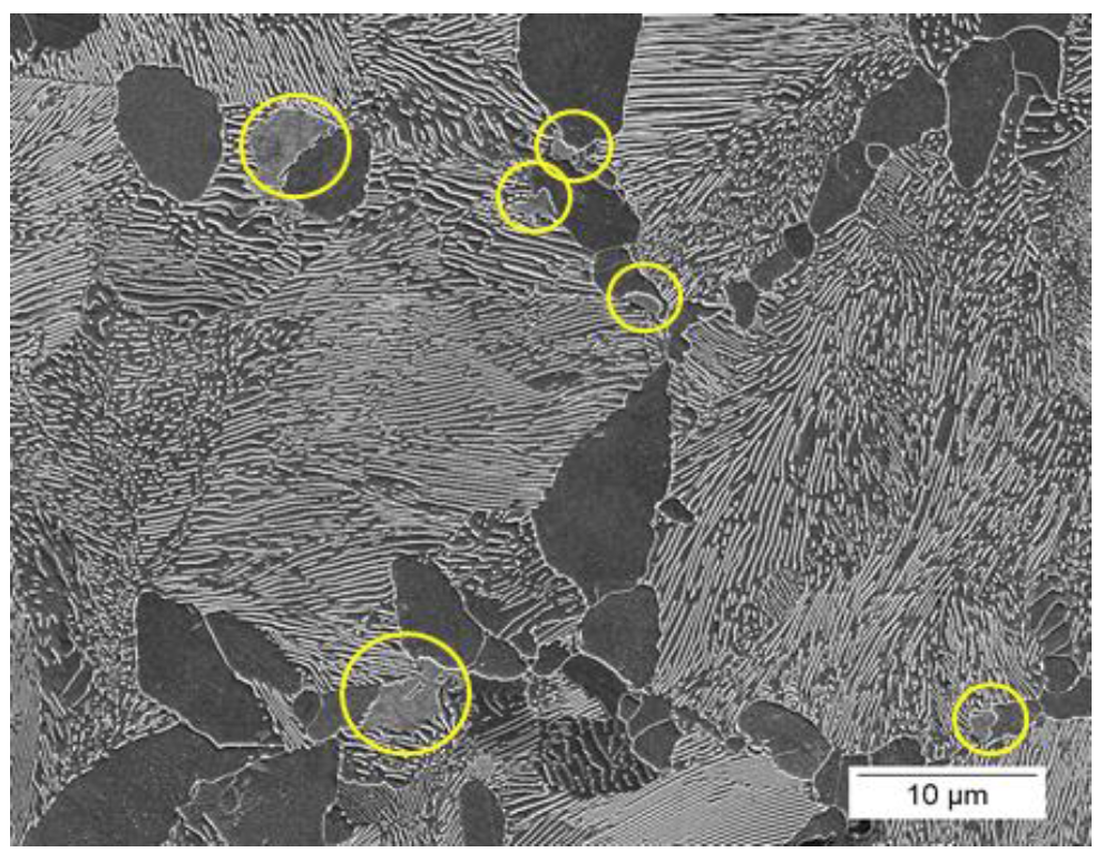 Figure 19: Representative secondary electron SEM image of the simulated total case depth in the 10V45 High condition. Only small regions of martensite are present and circled for emphasis. (2% nital etch.)
 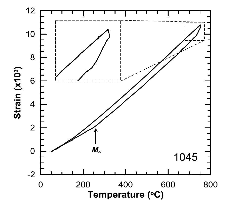 Figure 20: Representative dilatometry curve of the simulated total case depth in the 1045 High condition.
  Figure 21: Representative dilatometry curve of the simulated total case depth in the 10V45 High condition.
Conclusions
- Vanadium microalloying was observed to result in an induction hardened case microstructure with more observed non-martensitic transformation products; however, the NMTP did not influence hardness significantly due to very low volume fractions being present.
- Gleeble® simulations of the High condition total case depth thermal profiles showed ~1% austenite formed in the 10V45 steel while ~13% austenite formed in the 1045 steel, indicating that V microalloying may reduce the total case depth appreciably at the higher case depths.
Acknowledgements
This research was completed as part of Lee Rothleutner’s doctoral thesis. The authors acknowledge the support of the Advanced Steel Processing and Products Research Center at the Colorado School of Mines; Inductoheat Inc. of Madison Heights, Michigan; Fluxtrol Inc. of Auburn Hills, Michigan; and Gerdau Specialty Steels North America. The authors also gratefully acknowledge the contributions of Jody Burke, Gerdau Specialty Steels; and Robert Cryderman, Colorado School of Mines.
References
[1] G. Krauss, Steels: Processing, Structure, and Performance, 1st ed., ASM International, 2005. [2] G.D. Fett and J.F. Held, “The Influence of Vanadium and Niobium on the Induction Hardenability of Steel,” Microalloyed HSLA Steels, pp. 459-462, 1988. [3] Z. Li, B.L. Ferguson, V. Nemkov, R. Goldstein, J.Jackowski, and G. Fett, “Effect of Quenching Rate on Distortion and Residual Stresses During Induction Hardening of a Full-Float Truck Axle Shaft,” J. Mater. Eng. Perform., vol. 23, no. 12, pp. 4170-4180, 2014. [4] ASM Committee on Induction Hardening, Induction Hardening and Tempering, American Society for Metals, 1964. [5] J. Orlich, A. Rose, and P. Wiest, Eds., Atlas zur Wärmebehandlung der Stähle. Düsseldorf, Germany: Verlag Stahleisen M.B.H., 1973. [6] Ph. Maynier, J. Dollet, and P. Bastien, “Prediction of Microstructure via Empirical Formulae Based on CCT Diagrams,” in The Hardenability of Steels: Concepts, Metallurgical Influences, and Industrial Applications, pp. 163-178, 1977. [7] D.L. Martin and F.E. Wiley. “Induction Hardening of PlainCarbon Steels –A Study of the Effect of Temperature, Composition, and Prior Structure on the Hardness and Structure after Hardening,” T. Am. Soc. Metal, vol. 34, pp. 351-406, 1945. [8] K.Z. Shepelyakovskiy, V.D. Zelenova, and G.A. Ostrovskiy, “Structure and Properties of Hardened Steel Layer in Induction Hardening,” Metal Sci. Heat Treat., vol. 4, no. 9 10, pp. 381-384, 1962. [9] K.Z. Shepelyakovskiy and G.A. Ostrovskiy, “Superhardness and Grain Size of Quenched Steel,” Metal Sci. Heat Treat., vol. 13, no. 4, pp. 317-319, 1971. [10] H.B. Aaron, “On the Kinetics of Precipitate Dissolution,” Metal Sci., vol. 2, no. 1, pp. 192-193, 1968. [11] M.J. Whelan, “On the Kinetics of Precipitate Dissolution,” Metal Sci., vol. 3, no. 1, pp. 95-97, 1969. [12] H.B. Aaron and G.R. Kotler, “The Effects of Curvature on the Dissolution Kinetics of Spherical Precipitates,” Metal Science, vol. 4, no. 1, pp. 222-225, 1970. [13] H.B. Aaron and G.R. Kotler, “Second Phase Dissolution,” Mater. Trans., vol. 2, no. 2, pp. 393-408, 1971. [14] A.L. Rivas, G.M. Michal, M.E. Burnett, and C.F. Musolff, “The Influence of Carbides on the Residual Stresses Present in Induction Hardened Microalloyed Steels,” 38th Mechanical Working and Steel Processing Conference Proceedings vol. 34, pp. 233-240, 1996. [15] A.L. Rivas, G.M. Michal, M.E. Burnett, and C.F. Musolff, “Vanadium Carbide Coarsening in Steels Subjected to Normalizing and Induction Hardening Heat Treatments,” in Fundamentals and Applications of Microalloying Forging Steels, Golden, CO, pp. 159-172, 1996. [16] A.L. Rivas and G.M. Michal, “Microstructural Evolution During Induction Hardening Heat Treatment of a Vanadium Microalloyed Steel,” in Mater. Sci. Forum, vol. 284 286, pp. 403-410, 1998. [17] N.C. Law and D.V. Edmonds, “The Formation of Austenite in a Low-Alloy Steel,” Metall. Trans. A, vol. 11, no. 1, pp. 33-46, 1980. [18] G.M. Michal and I.E. Locci, “Analysis of Microalloy Precipitate Reversion in Steels,” Scripta Metall., vol. 22, no. 11, pp. 1801-1806, 1988. [19] M.A. Grossmann, Elements of Hardenability. American Society for Metals, 1952. [20] ASTM Standard A255, “Test Methods for Determining Hardenability of Steel,” ASTM International, 2010. [21] B. Garbarz and F.B. Pickering, “Effect of Vanadium and Austenitising Temperature on Hardenability of (0.2-0.3)C-1.6Mn Steels With and Without Additions of Titanium, Aluminium, and Molybdenum,” Mater. Sci. Tech., vol. 4, pp. 117-126, 1988. [22] B. Garbarz and F.B. Pickering, “Effect of Austenite Grain Boundary Mobility on Hardenability of Steels Containing Vanadium,” Mater. Sci. Tech., vol. 4, pp. 967-975, 1988. [23] H. Adrian, “A Mechanism for Effect of Vanadium on Hardenability of Medium Carbon Manganese Steel,” Mater. Sci. Tech., vol. 15, no. 4, pp. 366-378, 1999. [24] H. Adrian and R. Staśko, “The Effect of Nitrogen and Vanadium on Hardenability of Medium Carbon 0.4% C and 1.8% Cr Steel,” Arch. Mater. Sci. Eng., vol. 33, no. 2, pp. 69-74, 2008. [25] L. Rothleutner, R. Cryderman, C.J. Van Tyne, and J. Burke, “Torsional Fatigue Performance of Induction Hardened 1045 and 10V45 Steels,” in Proceedings from ASM Heat Treat Society 28th Conference and Exposition, Detroit MI, Oct. 20-22, 2015. [26] D. Hernandez, B. López, and J.M. Rodriguez-Ibabe, “Ferrite Grain Size Refinement in Vanadium Microalloyed Structural Steels,” Materials Science Forum, vol. 500-501, pp. 411-418, 2005. [27] E.T. Turkdogan, “Causes and Effects of Nitride and Carbonitride Precipitation During Continuous Casting,” Iron & Steelmaker, vol. 16, no. 5, pp. 61-75, 1989. [28] ASM Committee on Induction Hardening, Induction Hardening and Tempering. Materials Park, OH: American Society for Metals, 1964.If you have more questions, require service or just need general information, we are here to help.
Our knowledgeable Customer Service team is available during business hours to answer your questions in regard to Fluxtrol product, pricing, ordering and other information. If you have technical questions about induction heating, material properties, our engineering and educational services, please contact our experts by phone, e-mail or mail.
Fluxtrol Inc.
1388 Atlantic Boulevard,
Auburn Hills, MI 48326
Telephone: +1-800-224-5522
Outside USA: 1-248-393-2000
FAX: +1-248-393-0277