Information
Authors: Valentin Nemkov, Robert Goldstein
Location/Venue: UIE Katowice, Poland
Topic: Heat Treating
Abstract
This presentation is a continuation of the optimal design analysis of scanning process and inductors for scan hardening of axles that had been reported in 2007 in two publications [1,2] and in presentation at a conference HES-07 in Padua, Italy [3]. Improvements based on coil optimization at two frequencies (1 and 3 kHz) have been reported in these presentations. Current article describes what additional improvements may be achieved when two frequnces are used during the process of heat treating.
Vehicle axles are parts that have been induction heat treated for many years. Demands for increased vehicle reliability, fuel economy and performance have led to more challenging heat treatment specifications for axles. While being asked to produce better product, the automotive parts suppliers face an increased competition and relentless demands to lower costs.
Introduction
This presentation is a continuation of the optimal design analysis of scanning process and inductors for scan hardening of axles that had been reported in 2007 in two publications [1,2] and in presentation at a conference HES-07 in Padua, Italy [3]. Improvements based on coil optimization at two frequencies (1 and 3 kHz) have been reported in these presentations. Current article describes what additional improvements may be achieved when two frequnces are used during the process of heat treating.
Vehicle axles are parts that have been induction heat treated for many years. Demands for increased vehicle reliability, fuel economy and performance have led to more challenging heat treatment specifications for axles. While being asked to produce better product, the automotive parts suppliers face an increased competition and relentless demands to lower costs.
Study
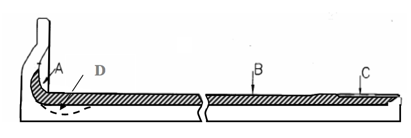
Typical design of full-float axle and hardness depth specification are shown in Fig. 1. Depending on the axle type and size hardness depth in regular zone B may reach 12-14 mm with special requirement of hardening of the root of the flange (zone A). On the other end the hardened layer must stop leaving soft the end of the spline zone C. The main challenge in scan hardening of axles is to provide required hardness pattern on the flange without too deep heating in adjacent area of the axle stem. Plus the induction coil must provide good scanning speed.
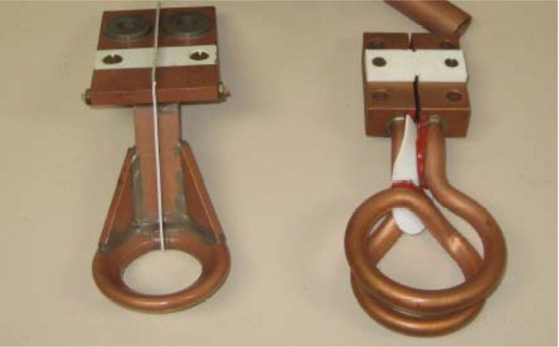
There are two main processes for induction heat treating axles–scanning and single shot. Majority of manufacturers use two-spindle scan hardening machines with three types of induction coils–single-turn Machined Integrated Quench (MIQ), single-turn and two-turn designs made of profiled tube (Fig.2). Single-turn coil is more favourable for heating of fillet area but it can not provide high scanning speed due to short length. Two-turn coil can provide high speed but it is difficult to achieve fillet hardening without too deep heating in zone D. To reduce overheating, the designers increase diameter of the upper turn and install the coil very close to the axle fillet (gap is around 1.5 mm). These measures solve the problem only partially and very accurate setup of the coil and power-time-speed regime is necessary. Another important factor is frequency. At higher frequency it is easier to achieve fillet hardening but scan speed dramatically drops.
An intensive study using computer simulation revealed that there was significant potential for cost savings in induction scanning processes by using optimally designed, precision machined inductors with magnetic flux controllers. The cost savings come in the form of improved part quality, reduced sensitivity to positioning, increased production rates and energy savings. These results have been validated in several production facilities on both semi-float and full-float axles.
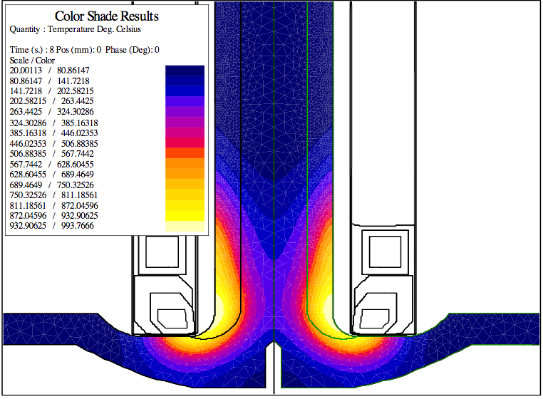
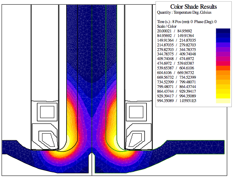
A full-float axle with diameter 48 mm was selected for a study. Required case depth in zone B was 10.5-14 mm. Computer simulation for a standard two-turn coil confirmed the practical results and showed sensitivity of the fillet heating to the axial gap between the coil and the axle flange. Fig.3 demonstates a map of temperature distribution in the axle after dwell heating for 8 seconds with standard two-turn coil at frequency 1 kHz. It may be seen that there is a tendency for overheating in zone D, which increases when the scanning process begin. To minimize this overheating, the coil moves at high speed to the position where normal scanning begins.
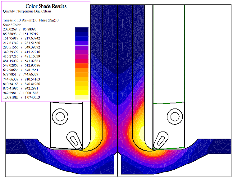
New optimized coil design has machined turns with C-shaped magnetic flux controller on the lower turn. Magnetic controller made of Fluxtrol A plays a critical role in this design, concentrating power on fillet surface and reducing heating of the stem. Diameter of the upper turn is larger than that of the lower turn but too much less extend than in the standard coil. This leads to higher efficiency and power factor of the coil and to stronger preheating and therefore higher speed in scanning regime. Temperature distribution after 8 second of dwell heating with new coil is shown in Fig.4.
It was assumed in this study that the power source can deliver 100 kW to the coil and the simulation showed that with optimized inductor provides the scanning speed 11 mm/sec compared to 9.5 mm /sec for a standard coil, over 15%. In both cases the speed was limited by available power and not by the maximum allowable surface temperature (1100 C) and better performance of optimized coil is only due to higher coil efficiency and better power utilization in the part.
Similar study for 3 kHz revealed that both standard and optimized coils can provide good heating in fillet area without special problem with setup. Scan speed, limited by acceptable temperature, was 9 mm/sec for optimized coil compared to 6.5 mm/sec for the standard coil, i.e 35% higher. Dwell time encreased to 12 seconds.
The results of this study led to an idea to combine advantages of two frequencies in one process. Induction heat treating power supplies continue to evolve, which opens up further opportunities for induction processing of the parts. One of the most important technological advancements is a possibility to apply to the coil two frequencies simultaneously [4] or to use 2 frequencies with nearly instantaneous switch from one to another. Both types of power supplies exist at present time, but they are designed for frequency range of 15-200 kHz. However the same method of power delivery may be implemented at any frequency range including that required for the optimal scan hardening of axles. Possibility to control frequency “on the fly” changes the criteria for induction coil and process optimization.
It was found by several iterations of simulation that the optimal induction coil for two-frequency heating is slightly different than optimal coils for 1 kHz or 3 kHz. The side of the lower turn facing the fillet surface may be shorter and diameter of the upper turn may be the same as for the lower turn. It was found also that dwell heating at 3 kHz only provides good pattern but time is too long (12 sec). An optimal strategy is to use higher frequency for a part of dwell heating and then to switch to lower frequency. Temperature distribution after heating for 4.5 sec at 3 kHz is shown in Fig. 5.
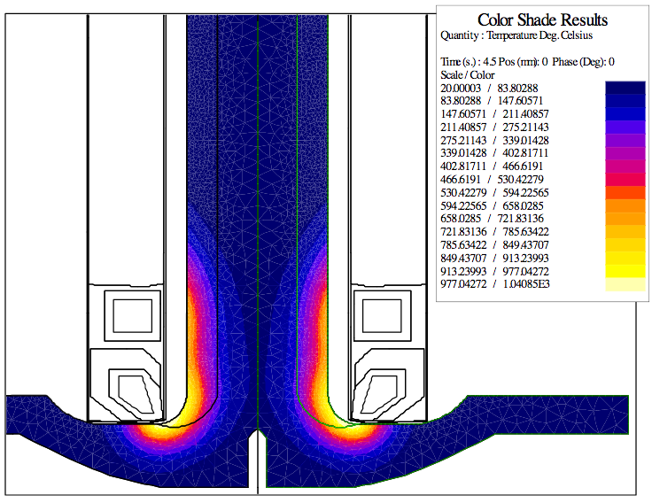
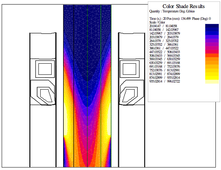
This picture shows that heating happens mainly in the bend area with small preheating of the axle body. Switch to 1 kHz with properly selected power and time results in fast and deep enough heating of the whole fillet area without overheating of zone D (Fig. 6). This distribution is favourable for fast transition to a regular scanning regime.
Scanning process takes place at 1 kHz with speed 11.5 mm/sec with limited power of 100 kW (Fig. 7). This small improvement is due to slightly higher efficiency of this coil compared to a previous one due to change in geometry.
If available power is higher than 100 kW, the scanning speed may be further increased until it will be limited by the acceptable surface temperature, heat extraction in quenching or other technological factors.
Comparison of simulation results for all considered cases is given in Table 1.
| Frequency, kHz | Coil | Dwell time, sec | Process setup | Coil current, kA | Scan speed, mm/sec | Speed limited by |
|---|---|---|---|---|---|---|
| 1.0 | Standard | 10 | Special | 13.5 | 9.5 | Power |
| Optimal | 8 | Normal | 13.5 | 11 | Power | |
| 3.0 | Standard | 12 | Normal | 7.0 | 6.5 | Temperature |
| Optimal | 12 | Normal | 8.0 | 9 | Temperature | |
| 3.0 + 1.0 | Optimal | 8 | Easy | 13.0 | 11.6 | Power |
Conclusions
Previous study using computer simulation revealed that there is significant potential for cost savings by using optimized regimes and precision machined inductors with selective use of magnetic flux controllers. It was shown also that frequency of 3 kHz is more favourable for heating of the flange area during the dwelling stage while frequency of 1 kHz is more adequate for fast scanning of the axle stem.
Present intensive study shows advantages of using frequency variable during the part processing. The progress in the power supplies are able to deliver to the induction coil the power of two frequencies simultaneously or to switch from one frequency to another “on the fly”. This method makes possible to have optimal conditions for both scanning and dwelling stages of hardening and can provide better quality, which is very essential for some critical deep hardening of heavy loaded axles, reduce process sensitivity to the system parameter variation and increase production rate compared to a single frequency process.
References
[1] Goldstein, R., Nemkov V., Madeira R.: Optimizing axle scan hardening inductors, ASM International Conference, Detroit, 2007
[2] Nemkov V., Goldstein R.: Optimization of induction scan hardening of automotive axles. J. of Induction Heating, n.2, December 2007 (in Russian)
[3] Nemkov V., Goldstein R., Ruffini R.: Optimal design of induction coils with magnetic flux controllers. Presentation at the International Symposium on Heating by Electromagnetic Sources, Padua 2007
[4] Schwenk, W.: SDF induction heating provides accurate contour hardening of PM parts, Industrial Heating, 51, 2003
If you have more questions, require service or just need general information, we are here to help.
Our knowledgeable Customer Service team is available during business hours to answer your questions in regard to Fluxtrol product, pricing, ordering and other information. If you have technical questions about induction heating, material properties, our engineering and educational services, please contact our experts by phone, e-mail or mail.
Fluxtrol Inc.
1388 Atlantic Boulevard,
Auburn Hills, MI 48326
Telephone: +1-800-224-5522
Outside USA: 1-248-393-2000
FAX: +1-248-393-0277