Information
Authors: Sean M. Muyskens, Tareq I. Eddir, Robert C. Goldstein
Publication: COMPEL, 2019
Abstract
Purpose: This paper aims to demonstrate the benefits of using different impeder materials for induction tube welding systems.
Design/methodology/approach: To show the difference in using various impeder materials, a new approach was taken to model tube welding systems in two and three dimensions. Three-dimensional (3-D) electromagnetic models were used to determine the current distribution along the weld vee as well as the permeability of the tube along the length of the welding system. Two-dimensional (2-D) coupled electromagnetic plus thermal models with rotational movement were used to determine the temperature distribution in the heat-affected zone.
Findings: Simulation results suggest upwards of 25 percent system power savings when using a soft magnetic composite (SMC) impeder rather than the traditional ferrites.
Research limitations/implications: There is currently a lack of experimental data to validate the models, but future work will include comparison of models to real-world trials.
Practical implications: When dealing with tube welding systems, there are possibilities to improve process efficiency or increase production quality and output by improving the impeder material.
Originality/value: While simulations of tube welding systems have been done previously, studies on improving impeder materials are rarely carried out. This paper brings to light possible improvements to be made to induction tube welding systems.
Keywords: Induction heating, Soft magnetic materials, Material modeling, Thermal analysis
Paper type: Research Paper
Introduction
Induction welding is a popular method for making tubes used in a variety of industries. One of the key components of the system, the impeder, is limiting the production rate or resulting product quality in some tube welding systems. Impeders are typically manufactured using a combination of construction elements and ferrite rods or tubes (ferrites). Ferrites have low saturation flux density and are strongly temperature sensitive. This becomes more critical at lower frequencies, where the desirable flux density for welding is higher. This new situation creates an opportunity to improve the welding system performance using soft magnetic composites (SMCs) (Goldstein, 2014; Nemkov, 2008).
The use of two-dimensional (2-D) models for studying the temperature distribution in the weld vee, along with weld angle, welding speed and wall thickness was originally demonstrated by Asperheim et al. (1998) and Asperheim and Grande (2000) in the late 1990s and early 2000s corresponding with the new high power insulated-gate bipolar transistor (IGBT) development. Recently, several publications have discussed the use of advanced three-dimensional (3-D) coupled models with moving thermal fields to predict temperature distributions in welded tubes and overall system performance (Das et al., 2017; Dughiero et al., 2011; Frame, 2017; Nikanorov et al., 2015). These models provide a substantial improvement to the ability to simulate and design the process compared to previous efforts. The drawback of these models is the time taken for calculations, which may last several days to weeks.
In this paper, a combination of 2-D and 3-D coupled models will be used for the study, design and optimization of the tube welding process to reduce the computational time to a few hours. Three-dimensional electromagnetic models will be used to determine the current distribution along the weld vee and permeability of the tube along the length of the welding system. Two-dimensional coupled electromagnetic plus thermal models with rotational movement will be used to determine the temperature distribution in the heat-affected zone. A comparison will be made between impeders designed using SMCs and traditional ferrite impeders for use in a typical tube size.
Model Description
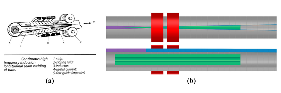
In an induction tube welding system, a steel sheet is formed into the profile of a tube by a series of rollers. The edges of the strip form a vee shape, referred to as the weld vee, which terminates at the apex or touching point. Just past the apex, a set of rollers applies pressure to create a solid-state bond. Near the last set of rollers, an induction coil is placed over the tube. Finally, an impeder is placed on the inside of the formed profile that extends from before the induction coil to near the apex. A basic geometry of the system is shown in Figure 1(a) (Lupi and Muhlbauer, 1992).
Currents are induced around the body of the strip under the induction coil; three main options for the current to flow are: along the edge towards the apex, along the edge towards the incoming material, or along the inside diameter (ID) of the tube. The current flowing along the edge of the vee generates the heat necessary for the solid-state welding process (Scott, 2014).
Altair FluxTM software (www.altairhyperworks.com) was used for the development of the computer models, using the standard multiphysics package. Figure 1(b) shows a 3-D electromagnetic model of the welding system. Half of the geometry is used in the model because of symmetry. The model includes the heat face of the induction coil turns (red elements), an equivalent geometry for the tube (grey element) in the welding region of the tube mill and an impeder (green element).
Near the edge of the weld vee, the tube is segmented into narrow regions radially (blue elements). This is for two reasons: increased mesh density in this area where the current changes directions and subsequent integration of the axial component of current. As the tube approaches the apex, the regions get progressively thicker to compensate for the material property change as the material heats and transitions from magnetic to nonmagnetic (magenta elements).
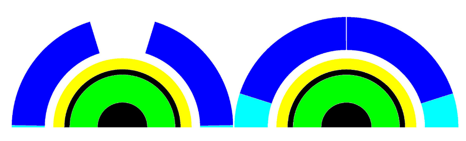
The 2-D model is one-quarter of a radial section of the tube, without the coil components. On the central axis, a superconducting boundary condition is used, and on the lower axis, a super magnetic boundary is used.
To simulate the tube welding system, the tube rotates during the calculations. Limited time for thermal conduction and relatively reduced axial current generated far from the vee edges allow for simplification of the tube into two segments: an upper region that is thermally active (dark blue) and a lower region that is thermally inactive (light blue). During rotation, the thermally inactive region stretches allowing for the profile to nearly close. This eliminates the need for a complex algorithm for moving thermal fields. Figure 2 shows a cross section of the 2-D model at the beginning (open) and end (nearly closed) of the welding process.
A time-dependent current (representing position in the 3-D system) is applied directly to the section of the tube that is thermally active. The current dynamics are taken from the 3-D electromagnetic model at different axial tube segments. These current levels are approximated to be linear between segments and are used in the 2-D models to evaluate the temperature along the edge and locate where the transition from magnetic to non-magnetic material is made in the tube.
Using the information from the 2-D models, the 3-D electromagnetic model is run with the adjusted position of the magnetic non-magnetic transition and an adjusted level of coil current. The new current distribution in the vee edge is then exported for use in additional 2-D simulation. The process is repeated until there are minimal changes in the respective models. Usually two to four iterations are required.
Case Study Conditions
The outside diameter (OD) of the finished tube is 40mm with 6-mm wall thickness. The two-turn induction coil has an ID of 50mm and total length of 50mm. The distance from the end of the coil to the apex is 60mm. The magnetic component of the impeder has an OD of 19 mm, ID of 9mm and a length of 225 mm. A comparison is made between Tokyo Denki Kagaku ferrites and Fluxtrol A. The weld vee angle is 2 degrees. The target line speed is 20 m/min, and the frequency used for initial study is 200 kHz. The minimum temperature in the cross section of the tube at the apex was set to 900°C, based upon typical AC3 values for low carbon steel. Based on the provided line speed and a length of 285mm from the start of the system to the apex, the heating time is about 0.86 s. The impeder geometry, weld vee angle, distance from the induction coil to the apex, induction coil design and line speed were determined based on discussions with Elva Fritz Düsseldorf induction (Andrus and Mitchell, 2019) and with reference to the electronic heating equipment (EHE) Catalog (EHE Consumables, 2019).
Results of Study
Soft coupling iterations between 3-D and 2-D models were run, and a comparison of required electrical parameters and minimum weld temperatures is presented in Table I. Temperature distributions at the end of heating are shown in Figure 3.
| Impeder | Coil Current (A) | Coil Power (kW) | Weld Vee Tmin (°C) | Weld Vee Tmax (°C) |
|---|---|---|---|---|
| Fluxtrol A | 1800 | 73 | 915 | 1205 |
| Ferrite Same Temperature | 2400 | 82 | 910 | 1197 |
| Ferrite Same Coil Current | 1800 | 54 | 714 | 960 |
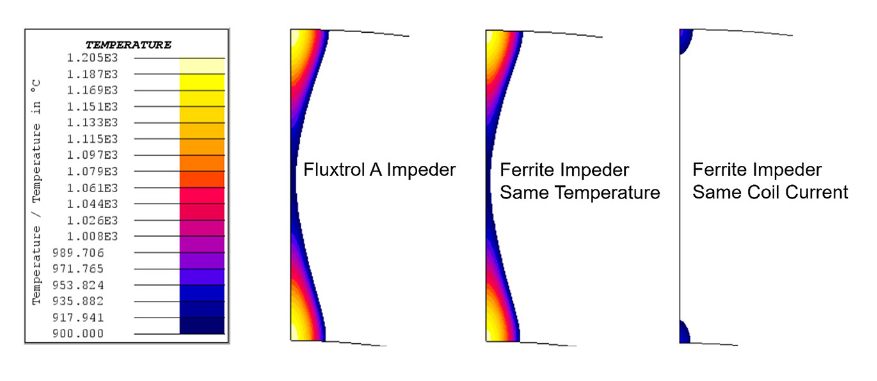
Using an impeder made of Fluxtrol A results in a significantly lower required coil current and coil head power. The coil current is reduced by 25 percent, and the coil head power is reduced by 11 percent to form an equivalent weld. The real power reduction realized for this type of tube will likely be closer to 25 percent when considering additional losses in the coil leads, heat station and power-supplying components.
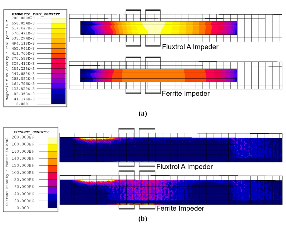
This difference stems from the saturation flux density of the two materials. The distribution of magnetic flux density in the impeder is shown in Figure 4(a). It can be seen that the main impeder loading comes from the coil magnetic flux, rather than the flux density associated with the current flowing along the weld vee. In addition, the flux density is shifted towards the back of the coil rather than being under the centre of the inductor. This occurs because the weld vee gets progressively wider, reducing the magnetic reluctance in this region and resulting in additional flux passing through the vee opening.
Ferrites saturate at approximately 0.41T, whereas Fluxtrol A is well below its saturation flux density of 1.4T. Once the ferrite reaches saturation, current begins to flow around the ID of the tube as opposed to along the edges of the weld vee. This internal current is the source of the difference in current between the two cases. The main concentrations of current density are along the edge of the weld vee leading towards the apex. There is a drop in current density just past the end of the induction coil because of the transition from magnetic to non-magnetic in the tube. Once the outer layer is non-magnetic, the current flows much deeper in the part, resulting in lower current density on the edge of the vee. The current density along the edge of the weld vee going back towards the incoming material is smaller than going to the apex, but still significant.
Figure 4(b) shows the distribution of current density on the tube in regions excluding the weld vee edges. It can be observed that the current is flowing along the ID of the tube in the area where the impeder was saturated. The associated increased current density in the OD of the tube under the face of the coil is also seen. When using the Fluxtrol A impeder, current does not return along the ID of the tube under the induction coil. This additional current density explains the higher current required while using the ferrite impeder as compared to the Fluxtrol A impeder. Another band of current can be seen flowing along the ID of the tube after the end of the impeder acting as a return pathway.
While Fluxtrol A has greater saturation flux density than ferrite and can better control the field, it must have proper water cooling to ensure impeder longevity, as the material can begin to degrade when exposed to elevated temperatures. A maximum operating temperature of 250°C should not be exceeded within the impeder. As loading and losses are non-uniform, proper water cooling needs to be achieved in the most heavily loaded area under the second turn of the inductor. Based on the loading seen above, losses in the Fluxtrol A impeder in this area would be approximately 280 MW/m^3 at 0.7T and 200 kHz (Vaishnava and Goldstein, 2019). A quick thermal model was run to determine the steady-state temperature of the Fluxtrol A impeder under these conditions assuming a cooling water inlet of 60 PSI at 30°C. The results show that the area with the highest loading in the Fluxtrol A impeder can be cooled to temperatures below 100°C, given these conditions.
Conclusions
For tube welding applications where the ferrite impeder cores are experiencing some degree of magnetic saturation, it has been found that SMCs have superior material properties and are able to improve the performance of induction tube welding systems. The greater saturation flux densities of SMCs allow for better control of ID tube current in these highly loaded systems compared to ferrites. The most notable improvement when switching from ferrite to Fluxtrol A is reduction in the required inductor current and system power for the same welding speed. Besides improving overall process efficiency, this benefits production in improved coil life, reduced heating of the rolls, decreased downtime and increased line speeds using the existing power supplies.
A new hybrid model for the efficient study and optimization of induction tube welding was proposed using loosely coupled 3-D electromagnetic and 2-D coupled magnetic and thermal models with motion. A case study of a 40-mm diameter tube with 6-mm wall thickness was used to demonstrate the model and make a comparison between ferrites and Fluxtrol A as impeder cores. The results show a 25 percent reduction in coil current and an 11 percent reduction in coil head power when switching from ferrites to Fluxtrol A. It is expected that the total system power reduction would be close to 25 percent for these conditions in the field because of the benefits of lower coil current on losses in coil leads, heat station and power-supplying components. The improvements are consistent with the authors’ experience in various tube welding trials.
Work is currently underway to validate the new modelling technique and the performance improvements of SMCs in these applications. In parallel with the model validation, additional work is being done to improve the model. Plans for 2019 include adding an external magnetic flux controller (bridge) to both the 2-D and 3-D models, fine tuning the 2-D simulation to consider variation in magnetic permeability in the length of the impeder and adding conductive components of the impeder assembly to the model. This will allow for more accurate depictions of the temperature distribution, as well as a study of how to improve weld system performance with an appropriate magnetic circuit design.
References
[1] Andrus, M. and Mitchell, G. (2019), “Discussions on the topic of tube welding systems”, Unpublished Correspondence, EFD Induction Inc, Madison Heights, MI.
[2] Asperheim, J.I., Grande, B., Markegård, L., Buser, J.E. and Lombard, P. (1998), “Temperature distribution in cross-section of the weld vee”, Tube International, November 1998.
[3] Asperheim, J.I. and Grande, B. (2000), “Temperature evaluation of weld vee geometry and performance”, Tube International, Vol. 19 No. 110, pp. 497-502.
[4] Das, P., Petzold, T., Asperheim, J.I., Grande, B. and Höomberg, D. (2017), “Simulation of temperature profile in longitudinal welded tubes during high-frequency induction (HFI) welding”, ASM HTS Conference 2017, Curran Associates, West Chester, OH.
[5] Dughiero, F., Baake, E., Forzan, M., Dughiero, F., Forzan, M., Garbin, M., Pozza, C. and Sieni, E. (2011), “A 3D numerical FEM model for the simulation of induction welding of tubes”, COMPEL – The International Journal for Computation and Mathematics in Electrical and Electronic Engineering, Vol. 30 No. 5, pp. 1570-1581, doi: 10.1108/03321641111152720.
[6] EHE Consumables (2019), Product Catalog, EFD Induction Group, Buckley, WA.
[7] Frame, L.D. (2017), “Aspects of precise heat input control for high frequency welding”, ASM HTS Conference 2017, Curran Associates, West Chester, OH.
[8] Goldstein, R.C. (2014), “Magnetic flux controllers in induction heating and melting”, in Lampman, S.R. (Ed.), ASM Handbook Volume 4C, ASM International, Cleveland, OH, pp. 633-645.
[9] Lupi, S. and Muhlbauer, A. (1992), Induction Heating Industrial Applications, UIE “Induction Heating” working group, Paris.
[10] Nemkov, V. (2008), “Magnetic flux guide for continuous high frequency welding of closed profiles”. US Patent Application, US20080308550A1.
[11] Nikanorov, A., Baake, E. and Neumeyer, J. (2015), “Numerical simulation and investigation of high frequency tube welding process”, Applied Mechanics and Materials, Vol. 698, pp. 245-250.
[12] Scott, P.F. (2014), “Key parameters of high frequency welding”, A Thermatool Corp. Publication, available at: https://thermatool.com/resources/technical-papers/
[13] Vaishnava, P. and Goldstein, R.C. (2019), “Magnetic core loss behavior at high magnetic fields in magnetic materials”, HES 2019 Conference, Servizi Grafici Editoriali, Pomezia.
Corresponding Author
Sean Michael Muyskens can be contacted at: smmuyskens@fluxtrol.com
If you have more questions, require service or just need general information, we are here to help.
Our knowledgeable Customer Service team is available during business hours to answer your questions in regard to Fluxtrol product, pricing, ordering and other information. If you have technical questions about induction heating, material properties, our engineering and educational services, please contact our experts by phone, e-mail or mail.
Fluxtrol Inc.
1388 Atlantic Boulevard,
Auburn Hills, MI 48326
Telephone: +1-800-224-5522
Outside USA: 1-248-393-2000
FAX: +1-248-393-0277