Information
Authors: Sean M. Muyskens, Tareq I. Eddir, Robert C. Goldstein
Location/Venue: ASM HTS Heat Treat 2019 Detroit, Michigan
Abstract
Inductive welding is a popular method for making metallic tubes used in a variety of industries. A majority of these induction tube welding systems use internal magnetic flux controllers (impeders) to limit the current flowing on the ID of the tube under the induction coil. As higher power, solid state IGBT power supplies become more widely available for tube welding, and demand for lower cost tubes with higher strength to weight ratios increases, magnetic loading of these impeders is also increasing. Traditionally, impeders are made of ferrites which have a low saturation flux density and can become saturated in these demanding conditions. Saturation of the impeder results in greater currents on the tube ID and lower process efficiency and weld quality. In order to expand the upper operating range of these more demanding systems while maintaining the weld quality, a change in impeder material from ferrites to soft magnetic composites (SMC) with greater saturation flux densities is suggested, as well as the addition of external magnetic controllers (bridges).
In this paper, a comparison is made between induction systems with impeders constructed from traditional ferrites and those utilizing bridges and impeders made from SMCs. To do this, a simulation study will be used to estimate impeder flux density, required coil current, and temperature distribution at the end of heating when using impeders made of the two materials, with and without bridges. By soft coupling 3-D electromagnetic models with 2-D electromagnetic and thermal models, a fast and accurate depiction of the welding process can be achieved. A case study is presented comparing simulation results to experimental results.
Introduction
Simulation History
There is a growing demand for lower cost tube with higher strength to weight ratios, requiring lower frequencies and higher magnetic flux densities to maintain weld quality in some of these systems. The ferrite impeders traditionally used in these systems have low saturation flux density which places limitations on these heavy-walled systems. This new situation creates an opportunity to improve the system performance using soft magnetic composite materials with higher saturation flux densities for the impeder, as well as adding a magnetic bridge [1,2]. To demonstrate the potential process improvements to be made by changing impeder material in induction tube welding systems, 2-D and 3-D computer modelling will be used to compare impeders made from ferrite and SMC.
In the case of induction tube welding, 2-D models have been used since the late 1990s to study the effects of weld vee angle, welding speed, and wall thickness on temperature distribution in the weld vee. [3,4] These models provided a good way to make quick evaluations of the welding system performance but didn’t consider flux from the inductor and what effects that would have on impeder saturation and process dynamics. Recently, there have been many 3-D coupled models used to predict temperature distributions and overall system performance [5-7]. While accuracy of these simulations offers a great improvement over 2-D simulations alone, the time it takes to optimize a single study can be anywhere from several months to a year. Das, et. al. recently presented results of a specially developed coupled 3D model with improved solving times, but this model is not available to the public [8].
Muyskens, et. al recently presented a hybrid simulation method using 2-D and 3-D coupled models to provide both timely and accurate results with commercially available software [9]. 3-D electromagnetic models are used to determine the current distribution along the weld vee as well as the permeability of the tube along the length of the welding system. 2-D coupled electromagnetic plus thermal models with rotational movement are used to determine the temperature distribution in the heat affected zone. The run times for the individual 2-D or 3-D models are typically minutes to an hour or two, which allows for system study and optimization in a few weeks.
Improvements that have been made to these models include finer meshing, the addition of non-linear magnetic properties of the steel tube and a redefinition of how the weld vee is drawn so the geometry more closely matches real systems. The improved mesh and non-linear steel magnetic properties effect on model accuracy will be discussed. Geometry to include a bridge in the model has also been added and its effects on the system will be explored. To gauge the accuracy of this model, simulation results will be compared to field trial data comparing an SMC and Ferrite impeder.
Process Background
In induction tube welding, a steel sheet is formed into the profile of a tube by a series of rollers. The edges of the strip form a vee shape, referred to as the weld vee, and terminates at the apex or touching point. Just past the apex, a set of rollers apply pressure to create a solid-state bond. Near the last set of rollers, an induction coil is placed over the tube. Finally, an impeder is placed on the inside of the formed profile that extends from before the induction coil to near the apex. A basic geometry of the system is shown in Fig. 1 [10].
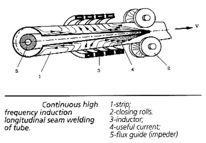
Currents are induced around the body of the strip under the induction coil and have three main options for which direction to flow: on the edge towards the apex, on the edge towards the incoming material, or along the inside diameter of the tube. The currents flowing along the edge of the vee are what generates the heat necessary for the solid-state welding process [11].
Simulation Description
Altair Flux™ software was used for the development of the computer models [12]. A picture representing a 3-D electromagnetic model of the welding system is shown in Fig. 2. Half of the geometry is used in the model due to symmetry. The model includes the heat face of the induction coil (red element), an equivalent geometry for the tube (cyan and magenta elements) in the welding region of the tube mill, as well as an impeder (green element) and external bridge (yellow element).
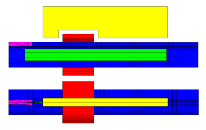
Near the edge of the weld vee, the tube is segmented into narrow volume regions radially. This is for increased mesh density in this area where current is changing directions and for subsequent integration of the axial component of current. As the tube approaches the apex, these regions on the welding face transition from magnetic (cyan) to non-magnetic (magenta elements) to compensate for the material property change as the material passes the curie temperature.
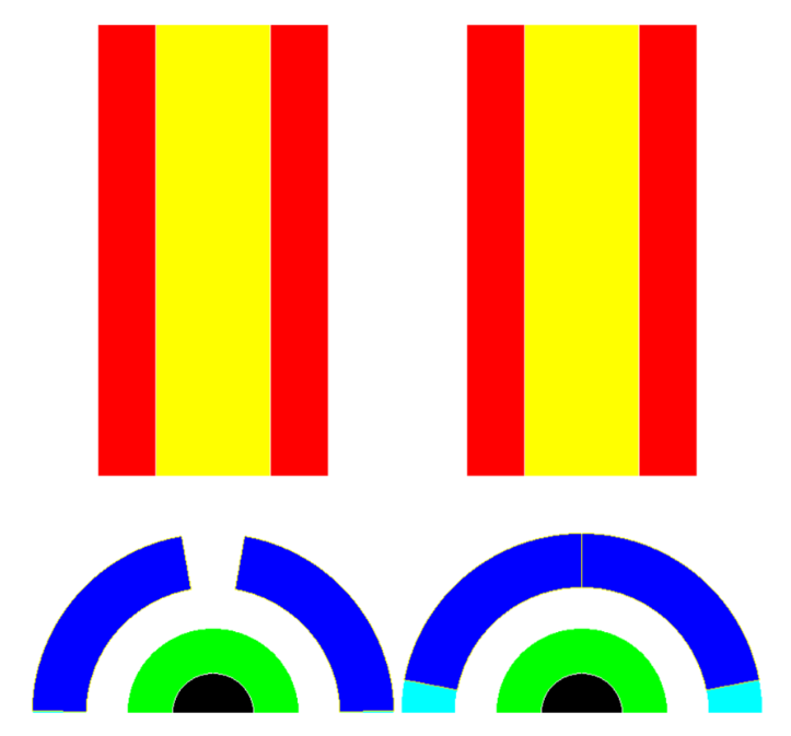
The 2-D model is ¼ of a radial section of the tube, without the coil components. On the central axis, symmetry and a superconducting boundary condition are used and on the lower axis, a super magnetic boundary is used.
To simulate the tube welding system, the tube closes in as the tube approaches the apex during the calculations. Limited time for thermal conduction and comparatively small axial current far from the vee edges allows for simplification of the tube into two segments, an upper region that is thermally active (dark blue elements) and a lower region that is thermally inactive (light blue elements). During rotation, the thermally inactive region stretches allowing for the profile to nearly close. This eliminates the need for a complex algorithm for moving thermal fields. Figure 3 shows a cross-section of the 2-D model at the beginning (open) and end (nearly closed) of the welding process. Along with the bridge (yellow elements) and impeder (green elements), copper cooling pates were added to the outside of the bridge for thermal models (red elements).
A time dependent current (representing position in the 3-D system) is applied directly to the section of the tube that is thermally active. The current dynamics are taken from the 3-D electromagnetic model at different axial tube segments. These current levels are approximated to be linear between segments and are used in the 2-D models to evaluate the temperature along the edge and locate where the transition from magnetic to non-magnetic material is made in the tube.
Using the information from the 2-D models, the 3-D electromagnetic model is run with the adjusted position of the magnetic to non-magnetic transition and an adjusted level of coil current. The new current distribution in the vee edge is then exported for use in additional 2-D simulation. The process is repeated until there are minimal changes in the respective models. Usually 2 to 4 iterations are required.
Simulation Study
Conditions
The OD of the finished tube is 40 mm with 6 mm wall thickness. The two-turn induction coil has an ID of 50 mm and total length of 50 mm. The distance from the end of the coil to the apex is 60 mm. The magnetic component of the impeder is 19 mm OD, 9 mm ID and 225 mm in length. A comparison will be made between TDK Ferrites and Fluxtrol A. The bridge is made of Fluxtrol A and is 12.7mm thick, 200mm long, 50mm tall, and is no closer than 6.35mm to the coil or tube. The weld vee angle is 2 degrees. The target line speed is 150 m/min and the frequency used for initial study is 200 kHz. The minimum temperature in the cross section of the tube at the apex was set to 900°C, based upon typical AC3 values for low carbon steel. Based on the provided line speed and a length of 240 mm from the start of the system to the apex, the heating time is about 0.096s. The impeder geometry, weld vee angle, distance from the induction coil to the apex, induction coil design, and line speed were determined based upon discussions with EFD Induction [13] and from the EHE Catalog [14].
Results
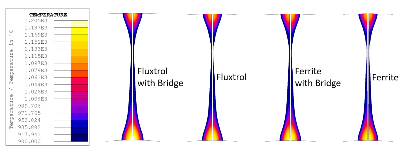
Soft coupling iterations between 3-D and 2-D models were run and only the final results are shown. A comparison of required electrical parameters and minimum weld temperatures can be seen in Table 1 and temperature distributions at the end of heating can be seen in Fig. 4 below.
| Magnetic Controllers | Coil Current (A) | Vee Edge Power (kW) | Weld Vee Tmin (°C) | Weld Vee Tmax (°C) |
|---|---|---|---|---|
| Fluxtrol A Impeder and Bridge |
4100 | 200 | 908 | 1203 |
| Fluxtrol A Impeder |
4500 | 198 | 902 | 1181 |
| Ferrite Impeder and Fluxtrol A Bridge | 5350 | 197 | 906 | 1194 |
| Ferrite Impeder | 5700 | 196 | 906 | 1181 |
In previous simulations using this case study at a lower speed (20 m/min), before the bridge was added to the models, it was observed that forming a proper weld using an impeder made of Fluxtrol A rather than Ferrite lead to a 25% lower required coil current. At this slower line speed, running the simulation using the improved mesh and non-linear steel properties showed much lower flux densities in each system. When operating below the saturation flux density of the ferrites, the two materials produce comparable results in terms of required coil currents. Additional discussions with practitioners revealed that the line speed used for this model is quite slow compared to those typically used in industry. Therefore, a line speed of 150 m/min was selected as this is close to the level considered state of the art in the field.
With the updates made to the model we see a similar 21% lower required coil current. Based on the reduction in coil current, there will most likely be a substantial power reduction for the system when considering less undesired heating of areas in the steel tube outside of the edge of the weld vee, as well as fewer losses in the coil leads, heat station and power supply components. There is further 9% lower required coil current when adding a Fluxtrol A Bridge to the Fluxtrol A Impeder system. A similar reduction can be seen when adding the bridge to a Ferrite impeder system. The reduction in current with the bridge is due to a decrease in the electromagnetic end effect on the top of the weld vee from the presence of the external magnetic component [9].
The magnetic bridge helps to concentrate current along the edge of the tube as it keeps the magnetic field parallel to the edges of the tube rather than letting it curve away towards the outside. This reduces the losses away from the welding face and leads to a more even temperature distribution. The overall improvement seen when switching the impeder material from Ferrite to a SMC stems from the difference in saturation flux density of the two materials. The distribution of magnetic flux density in the impeder and bridge is shown in Fig. 5. The most significantly loaded areas are around the inductor, with little flux originating from the weld vee currents. As the weld vee gets progressively wider, the reluctance of the magnetic circuit in this region is reduced, resulting in additional flux passing through the vee opening and shifting the most heavily loaded section of the impeder away from the apex under the inductor.
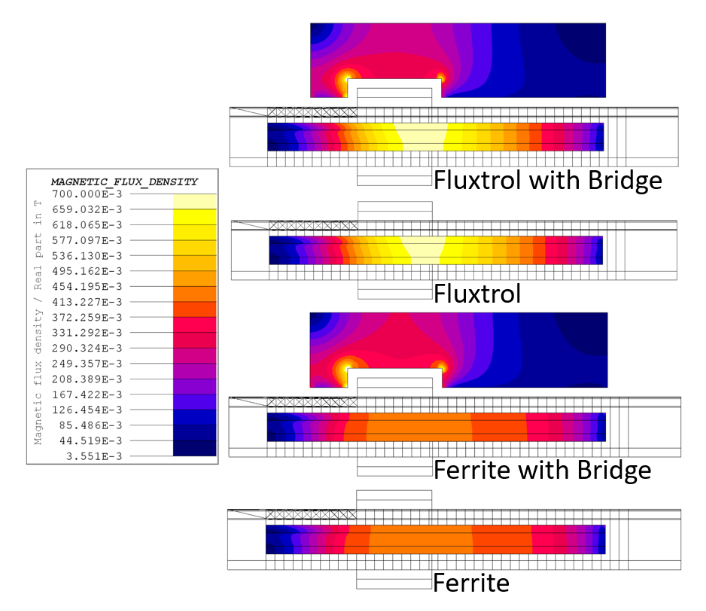
The Ferrite saturates at a magnetic flux density of ~0.41T, while the Fluxtrol A is well below its saturation flux density of 1.6T [15]. Once the Ferrite reaches saturation, some current begins to flow around the ID of the tube as opposed to along the edges of the weld vee. This internal current is the source of the difference in required coil current between the two impeder types. A representative current density distribution is shown in Fig. 6. A comparison isn’t shown as there will be little difference between each case as the coil current driving heating was that required to get the similar temperature distributions seen in Fig. 3. The main concentrations of current density are along the edge of the weld vee leading towards the apex. There is a drop in current density just past the end of the induction coil due to the transition from magnetic to non-magnetic in the tube. Once the outer layer is non-magnetic, the current flows much deeper in the part, resulting in lower current density on the edge of the vee. While it is difficult to see in this image, there is current along the edge of the weld vee going back towards the incoming material which is less than that going towards the apex, but still significant.
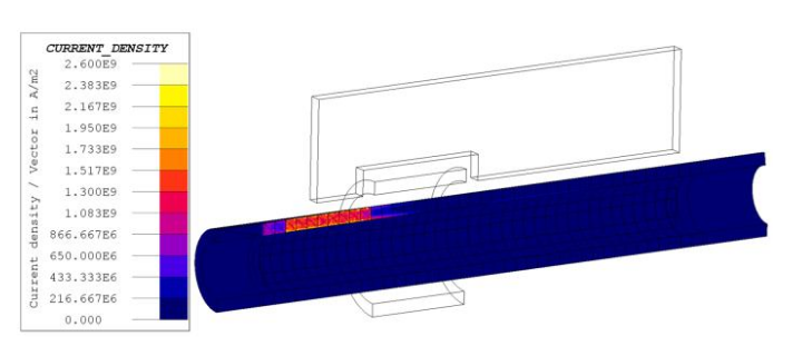
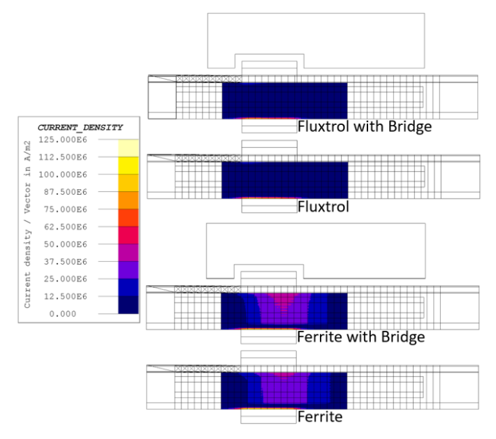
Figure 7 shows the distribution of current density on the ID of the tube under the inductor for each case. When using a Fluxtrol A impeder no current can be seen in the ID, but when using a Ferrite impeder, it saturates leading to current in this region. This additional current density can explain the higher required coil current when using the Ferrite impeder as compared to the Fluxtrol A impeder.
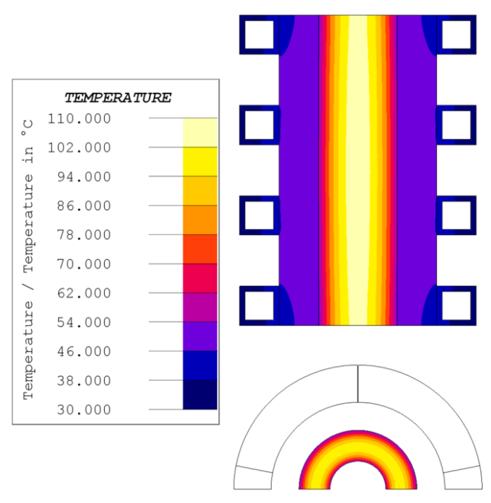
While SMCs have greater saturation flux density than Ferrites and can better control the field, they must have proper water cooling to ensure impeder longevity. This is not an issue of temperature dependent saturation flux density, but rather that the material can begin to degrade due to exposure to elevated temperatures. To ensure proper continuous use of Fluxtrol A, a maximum operating temperature of 250°C should not be exceeded within the impeder. As loading and losses are non-uniform, proper water cooling needs to be achieved in the most heavily loaded areas around the inductor. Based on the loading seen above at 200kHz, losses in the Fluxtrol A around the inductor would be ~280MW/m^3 at 0.7T in the impeder, and ~54MW/m^3 at 0.3T in the bridge in the most heavily loaded areas [16]. A thermal model was run to find the steady state temperature of the impeder and bridge under these conditions assuming a cooling water inlet of 60PSI at 30°C. This water cooling was applied directly to the OD and ID of the impeder, and to the inside of copper cooling tubes on the outside to the bridge structure. The result can be seen in Fig. 9, showing that the areas with the highest loading in the Fluxtrol A impeder can be cooled given these conditions.
Case Study
Preface
Trials were performed at an induction tube welding facility to gather practical data on how SMC impeders function in more demanding applications compared to traditional ferrite impeders. Process parameters were collected during each trial and used to compare simulated and experimental results. As each trial resulted in proper welds with both impeders, without an exact knowledge of the temperature at the apex, process parameters were put into the model and thermal results were evaluated to see if simulations would also predict a proper weld. The minimum temperature to form a proper weld at the apex was set to 900°C, based upon typical AC3 values for low carbon steel.
Generalized Conditions
The OD of the finished tube was ~19 mm with 3 mm wall thickness. The induction coil has an ID of ~25 mm and total length of 42 mm. The impeder was a through flow design with external casing. The magnetic cores (both ferrite and Fluxtrol 75) were 9 mm OD with flutes machined in the OD. A comparison will be made between TDK ferrites and Fluxtrol 75. The line speed was ~80 m/min, frequency was ~200 kHz, and trials lasted for ~20 min for both impeders. Based on the line speed and a length of 240 mm from the start of the system to the apex, the heating time is about 0.2 s. The impeder geometry, weld vee angle, distance from the induction coil to the apex, induction coil design, and line speed were determined based upon the experimental setup. The only required electrical parameter needed to run each model is the associated number of ampere turns of the inductor. For these trials, the current used was 5000A with the Fluxtrol 75 impeder, and 7300A with the ferrite impeder for the same line speed and weld quality.
Results
The models were run using the electrical parameters for each trial, and the results are shown. A comparison of actual electrical parameters and associated simulated weld temperatures can be seen in Table 2. Temperature distributions at the end of heating can be seen in Fig. 9 below.
| Magnetic Controllers | Coil Current (A) | Process Power (kW) | Weld Vee Tmin (°C) | Weld Vee Tmax (°C) |
|---|---|---|---|---|
| Fluxtrol 75 | 5000 | 200 | 997 | 1187 |
| Ferrite Impeder | 7300 | 325 | 263 | 337 |
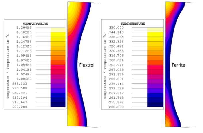
In both trials, a proper weld was formed and the switch to Fluxtrol 75 from Ferrite lead to an almost 30% drop in required coil current and 40% drop in required system power to run at the same speed. While simulated weld vee temperatures when using the Fluxtrol impeder are reasonable, as they are above minimum required welding temperatures and below molten steel temperatures, the models with ferrite impeders are underestimating weld temperatures significantly.
The authors believe that the source of the large error is likely in the non-linear description of the magnetic properties of the steel tube and the fact that the model does not take into account temperature in the tube in the areas outside of the weld vee. In the models, the steel tube was near its saturation flux density. A combination of tube diameter and magnetic non-linearity in the steel will have a strong effect on how much current flows on the ID of the tube and how much travels along the vee edge. As saturation grows in the steel tube, its reference depth declines, decreasing the ratio of reference depth to wall thickness in the magnetic regions. As this level declines, it will cause current cancellation, increasing the impedance for the return current flow on the ID of the tube. The normal mechanism of preventing the ID current flow is the impeder itself. Magnetic field in these simulations is much higher than that in the initial case study, and results are showing that even the Fluxtrol 75 impeder is close to its saturation flux density, while the TDK ferrite is well into saturation, providing little additional resistance to internal current flow. It is expected that due to the significantly higher coil currents, the heating of the area of the tube under the coil will be substantially higher with the ferrite. As temperature in the steel rises, steel resistivity rises and saturation flux density declines. Both of these factors will lead to a reduction in the electrical thickness and increase in resulting impedance to the ID return current flow. This should result in increased currents in the weld vee and resulting higher temperatures predicted in the models. Additional models will be run to investigate the role of the saturation flux density and local electrical resistivity change of the steel on the results.
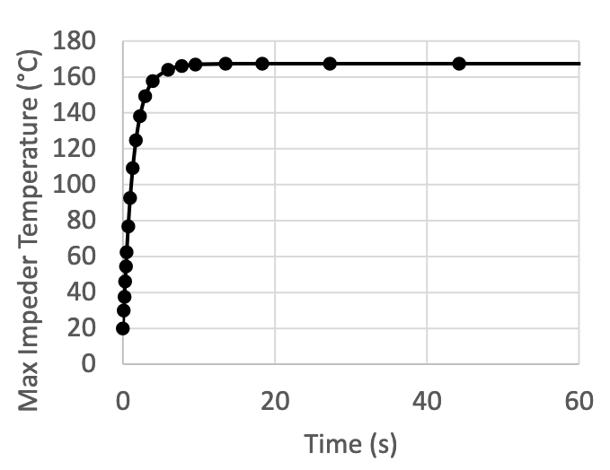
It is also worth noting that the Fluxtrol 75 did not fail due to overheating during the trials. Any failure due to overheating would be seen in under a minute due to the high losses and thermal conductivity of the impeder. The flux density was predicted to exceed 1 T in these conditions leading to losses of 350 MW/m^3, and a water-cooling inlet of 30PSI at ~30°C was sufficient to remove these losses. A graph of simulated max temperature in the impeder vs. time can be seen in Fig. 10. The impeder reaches steady state temperatures very quickly in these processes.
Conclusions
For tube welding applications where the ferrite impeder cores are experiencing some degree of magnetic saturation, it has been found that SMCs have superior material properties and are able to improve the performance of induction tube welding systems. This is a common occurrence on systems where there is either a small diameter tube, heavy-walled tube, or a combination of both being welded, especially when the systems are running at lower frequencies. The greater saturation flux densities of SMCs allow for better control of ID tube current in these highly loaded systems compared to ferrites. The most notable improvements when switching from ferrite to SMCs are a reduction in required inductor current and in required system power for the same welding speed. For some extreme cases, an improvement in component quality may be achieved if there is excessive heating in the areas of the tube not near the edges of the weld vee. Other than improving overall process efficiency, this benefits production in improved coil life, reduced heating of the rolls, reduced heating of the rest of the volume of the tube, decreased downtime and increased line speeds using existing power supplies. Some of these effects have been shown in simulation and observed when running experimental trials in a tube mill, including a reduction in required coil current of 30% and subsequent drop in required system power of 40% for the same welding speed and tube quality.
Improvements were made to a hybrid model using loosely coupled 3D electromagnetic and 2D coupled magnetic and thermal models with motion. A simulation study of a 40 mm diameter tube with 6 mm wall thickness was used to demonstrate the model and make a comparison between ferrites and SMCs as impeder cores. The results show a ~20% reduction in coil current when switching from Ferrites to Fluxtrol A and further improvements when adding a magnetic bridge to the system. A case study of a 19 mm diameter tube with a 3 mm wall thickness was used to verify the simulations. While the case study was for a tube roughly half the size, a similar result in lowered inductor current was seen, as well as a roughly 40% decrease in required system power. However, when attempting to model the case study geometry, simulations results were not lining up with experimental values. More case studies are required, and work is currently underway to validate the new modelling technique and performance improvements of SMCs in these applications. Further trials in tube welding mills on various tube sizes, production rates and impeder/bridge designs are planned during 2019. Detailed data will be taken on the electrical parameters of the system, process temperatures and other production details and compared to the models. Updates to the models will be made based upon the field data and presented at future events.
In parallel with the model validation, additional work is being done to improve the model. Future plans include fine tuning the simulations by adding considerations to variation in magnetic permeability in the length of the impeder and steel tube, adding further conductive constructive elements of the impeder and bridge assemblies to the model and studying the influence of steel properties on the welding parameters in very heavily loaded systems. This will allow for more accurate depictions of the temperature distribution, as well as a study of how to improve weld system performance with appropriate magnetic circuit design.
References
[1] R.C. Goldstein, ASM Handbook Volume 4C, ASM International (USA, 2014), p 633-645
[2] V. Nemkov, U.S. Patent US20080308550A1
[3] J.I. Asperheim, et al., “Temperature Distribution in Cross-Section of the Weld Vee,” Tube International, November 1998
[4] J.I. Asperheim, et al., “Temperature Evaluation of Weld Vee Geometry and Performance,” Tube International, Vol. 19, 2000, p 497-502
[5] A. Nikanorov, et al., “Numerical Simulation and Investigation of High Frequency Tube Welding Process,” Applied Mechanics and Materials, Vol. 698, 2015, p 245-250
[6] P. Das, J.I. Asperheim, et al., “Simulation of temperature profile in longitudinal welded tubes during High-Frequency induction (HFI) welding,” ASM HTS Conference, 2017
[7] L.D. Frame, “Aspects of Precise Heat Input Control for H
[8] P. Das, J.I. Asperheim, et al., “Three-dimensional numerical simulation of high frequency induction welding of steel tubes,” HES 2019 Conference
[9] S.M. Muyskens, et al., “Improving Induction Tube Welding System Performance Utilizing Soft Magnetic Composites,” HES 2019 Conference
[10] S. Lupi, et al., Induction Heating Industrial Applications, UIE “Induction Heating” working group (Paris, 1992), p 73
[11] P.F. Scott, “Key Parameters of High Frequency Welding,” A Thermatool Corp. Publication, https://thermatool.com/resources/technical-papers/
[12] Altair, “Hyperworks,” www.altairhyperworks.com
[13] M. Andrus, G. Mitchell, Discussions on the topic of Tube Welding Systems, EFD Induction Inc., 2019
[14] EHE Consumables, 2019, Product Catalog, EFD Induction Group
[15] Fluxtrol, “Fluxtrol A,” https://fluxtrol.com/fluxtrol-A
[16] P. Vaishnava, R. Goldstein, “Magnetic Core Loss Behavior at High Magnetic Fields in Magnetic Materials,” HES 2019 Conference
If you have more questions, require service or just need general information, we are here to help.
Our knowledgeable Customer Service team is available during business hours to answer your questions in regard to Fluxtrol product, pricing, ordering and other information. If you have technical questions about induction heating, material properties, our engineering and educational services, please contact our experts by phone, e-mail or mail.
Fluxtrol Inc.
1388 Atlantic Boulevard,
Auburn Hills, MI 48326
Telephone: +1-800-224-5522
Outside USA: 1-248-393-2000
FAX: +1-248-393-0277
Related Topics
- ASM HTS 2019 Improving Corrosion Resistance of Soft Magnetic Composites for Induction Heat Treating Applications
- ASM HTS 2019 Design Improvements to a Short Time Dilatometry Testing System as Applied to High Carbon Steels
- HES 2019 Improving Induction Tube Welding System Performance Utilizing Soft Magnetic Composites
- HES 2019 Magnetic Core Loss Behavior at High Fields in Magnetic Materials