Information
Authors: Sean M. Muyskens, Tareq I. Eddir, Robert C. Goldstein
Location/Venue: HES 19 Padova, Italy
Published Journal: COMPEL, 2019
Download Full Paper PDF
Download Presentation PDF
Abstract
Most induction tube welding systems use internal magnetic flux controllers (impeders) to limit the amount of current flowing on the ID of the tube under the face of the induction coil. More difficult applications of tube welding, such as smaller diameter tubing with thicker walls, can lead to high magnetic loading of the impeder. Traditional materials for the impeder are ferrites, which have low saturation flux densities, and can easily become saturated in these systems. This increases the amount of current flowing on the ID of the tube and leads to inefficient heating or inability to form a proper weld. To maintain process efficiency and weld quality in these applications, a switch in impeder material to soft magnetic composites (SMCs) with higher saturation flux density is suggested. In this paper, a comparison is made between impeders constructed from traditional ferrite materials, and SMCs. To make this comparison, a hybrid method of simulating the induction tube welding process was created utilizing a combination of 2-D and 3-D coupled models. By soft coupling 3-D electromagnetic models with 2-D electromagnetic and thermal models, a fast and accurate depiction of the welding process can be achieved. A case study is presented comparing ferrite and SMC impeders in a representative induction tube welding application.
Introduction
Inductive welding is a popular method for making tubes used in a variety of industries. Over the past 20-30 years, the industry has been transitioning from tube generators operating at 400 kHz, to solid state generators (either IGBT or MOSFET) which operate at frequencies from 50 kHz to 400 kHz. The availability of high power at lower frequencies has created the opportunity to successfully weld larger tubes with greater wall thicknesses for more demanding applications. At the same time, one of the key components of the system, the impeder, has not changed significantly, which is limiting the production rate or resulting quality of some types of tubing.
Impeders are typically manufactured using a combination of construction elements and ferrite rods or tubes (ferrites). Ferrites have a low saturation flux density which is strongly temperature sensitive, are limited in size availability and are very susceptible to mechanical and thermal shock. The saturation flux density becomes more and more of an issue for lower frequencies, where the desirable flux density for welding is higher. This new situation creates an opportunity to improve the welding system performance using SMCs [1, 2].
The use of 2-D models for studying the temperature distribution in the weld vee, along with weld angle, welding speed and wall thickness was originally demonstrated by Asperheim, et. al. [3, 4] in the late 1990s and early 2000s corresponding with the new high power IGBT development. In these models, the source of the flux density considered was the current in the weld vee. The proposed method provided a good way to make a quick evaluation of welding system performance.
Recently, several publications have been made on the use of advanced 3-D coupled models with moving thermal fields to predict temperature distributions in welded tubes and overall system performance [5-7]. These models provide a substantial improvement to the ability to simulate and design the process compared to previous efforts. The drawback of these models is the time for the calculations, which can be several weeks per case studied. A design and optimization process using this method can take several months to over a year, making it viable for very complicated processes found in research and development projects, but limits its use as a routine tool for practical problem solution and system improvement.
In this paper, a new hybrid method utilizing a combination of 2-D and 3-D coupled models will be used for study, design and optimization of the tube welding process. The models will incorporate magnetic flux controllers and quantify their role in improving the welding process.
3-D electromagnetic models will be used to determine the current distribution along the weld vee as well as the permeability of the tube along the length of the welding system. 2-D coupled electromagnetic plus thermal models with rotational movement will be used to determine the temperature distribution in the heat affected zone. A comparison will be made between impeders designed using SMCs and traditional ferrite impeders for use in a typical tube size.
The run times for the individual 2-D or 3-D models are typically minutes to an hour or two, which allows for system study and optimization in a few weeks.
Model Description
In induction tube welding, a steel sheet is formed into the profile of a tube by a series of rollers. As the profile is nearly formed, the edges of the strip form a vee shape, which is referred to as the weld vee. The point at which the vee terminates is often referred to as the apex or touching point. Just past the apex, a set of rollers apply pressure to create a solid-state bond. The size of the rollers depends upon the characteristics of the tube that is being welded. Near the last set of rollers, an induction coil is placed over the tube. Finally, an impeder is placed on the inside of the formed profile that extends from before the induction coil to near the apex. A basic geometry of the system is shown in Figure 1 (a) [8].
Currents are induced around the body of the strip under the induction coil. As the currents approach the edge of the vee, the currents have three main options for which direction to flow: on the edge towards the apex, on the edge towards the incoming material, or along the inside diameter of the tube. The currents flowing along the edge of the vee are what generates the heat necessary for the solid-state welding process [9].
Flux software (www.altairhyperworks.com) was used for the development of the computer models. A picture of a 3-D electromagnetic model of the welding system is shown in Figure 1 (b). ½ of the geometry is used in the model due to symmetry. The model includes the heat face of the induction coil turns (red elements), an equivalent geometry for the tube (grey element) in the welding region of the tube mill, and an impeder (green element).
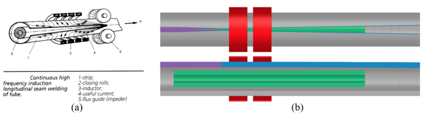
Near the edge of the weld vee, the tube is segmented into narrow regions radially (blue elements). This is for two reasons, increased mesh density in this area where current is changing directions and for subsequent integration of the axial component of current, which is what will be exported to the 2-D models for electromagnetic and thermal computations. The tube is also segmented axially to calculate the current in the vee at different positions for export to the 2-D models. As the tube approaches the apex, the regions get progressively thicker. This is to compensate for the material property change as the material heats and transitions from magnetic to non-magnetic (magenta elements).
The 2-D model is ¼ of a radial section of the tube, without the coil components. On the central axis, a superconducting boundary condition is used and on the lower axis, a super magnetic boundary is used.
To simulate the tube welding system, the tube rotates during the calculations. Due to the speed of the process, there is insufficient time for thermal conduction of the power generated from axial currents in the weld vee around the perimeter of the tube. There is also negligible axial current in the area of the profile relatively far from the vee edges. This allows for simplification of the tube into two segments, an upper region that is thermally active (dark blue) and a lower region that is thermally inactive (light blue). During rotation, the thermally inactive region stretches allowing for the profile to nearly close. This eliminates the need for a complex algorithm for moving thermal fields. Figure 2 shows a cross-section of the 2-D model at the beginning (open) and end (nearly closed) of the welding process.

A time dependent current (representing position in the 3-D system) is applied directly to the section of the tube that is thermally active. The current dynamics are taken from the 3-D electromagnetic model at different axial tube segments. These current levels are approximated to be linear between segments and are used in the 2-D models to evaluate the temperature along the edge and locate where the transition from magnetic to non-magnetic material is made in the tube. The system is also assumed to be linear for adjustment of the current level.
Using the information from the 2-D models, the 3-D electromagnetic model is run with the adjusted position of the magnetic non-magnetic transition and an adjusted level of coil current. The new current distribution in the vee edge is then exported for use in additional 2-D simulation. The process is repeated until there are minimal changes in the respective models. Usually 2 to 4 iterations are required.
The combination of rotation, magnetic components, and time varying current will allow for better prediction of the temperatures in the tube cross-section compared to the linear models of Asperheim, et. Al ([3, 4].
Case Study Conditions
The OD of the finished tube is 40 mm with 6 mm wall thickness. The two-turn induction coil has an ID of 50 mm and total length of 50 mm. The distance from the end of the coil to the apex is 60 mm. The magnetic component of the impeder is 19 mm OD, 9 mm ID and 225 mm in length. A comparison will be made between TDK ferrites and Fluxtrol A. The weld vee angle is 2 degrees. The target line speed is 20 m/min and the frequency used for initial study is 200 kHz. The minimum temperature in the cross section of the tube at the apex was set to 900°C, based upon typical AC3 values for low carbon steel. Based on the provided line speed and a length of 285 mm from the start of the system to the apex, the heating time is about 0.86 s. The impeder geometry, weld vee angle, distance from the induction coil to the apex, induction coil design, and line speed were determined based upon discussions with EFD Induction [10] and from the EHE Catalog [11].
Results of Study
Soft coupling iterations between 3-D and 2-D models were run and only the final results are shown. A comparison of required electrical parameters and minimum weld temperatures can be seen in Table 1 and temperature distributions at the end of heating can be seen in Figure 3 below.
| Impeder | Coil Current (A) | Coil Power (kW) | Weld Vee Tmin (°C) | Weld Vee Tmax (°C) |
|---|---|---|---|---|
| Fluxtrol A | 1800 | 73 | 915 | 1205 |
| Ferrite Same Temperature | 2400 | 82 | 910 | 1197 |
| Ferrite Same Coil Current | 1800 | 54 | 714 | 960 |
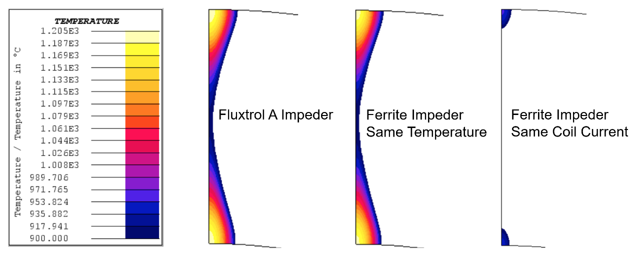
Using an impeder made of Fluxtrol A compared to a traditional Ferrite results in a significantly lower required coil current and coil head power. The coil current is reduced by 25% and the coil head power is reduced by 11% (does not include losses in the coil leads, heat station or power supplying components) to form an equivalent weld. The real power reduction realized for this type of tube will likely be closer to 25% when considering additional losses in the coil leads, heat station and power supplying components.
This difference stems from the saturation flux density of the two materials. The distribution of magnetic flux density in the impeder is shown in Figure 4. It can be seen clearly from the figure that the main impeder loading comes from the coil magnetic flux, rather than the flux density associated with currents flowing along the weld vee. It can also be seen that the flux density is shifted towards the back of the coil rather than being under the center of the inductor. This occurs because the weld vee gets progressively wider, reducing the reluctance of the magnetic circuit in this region and resulting in additional flux, that was coupling with the tube, to pass through the vee opening.
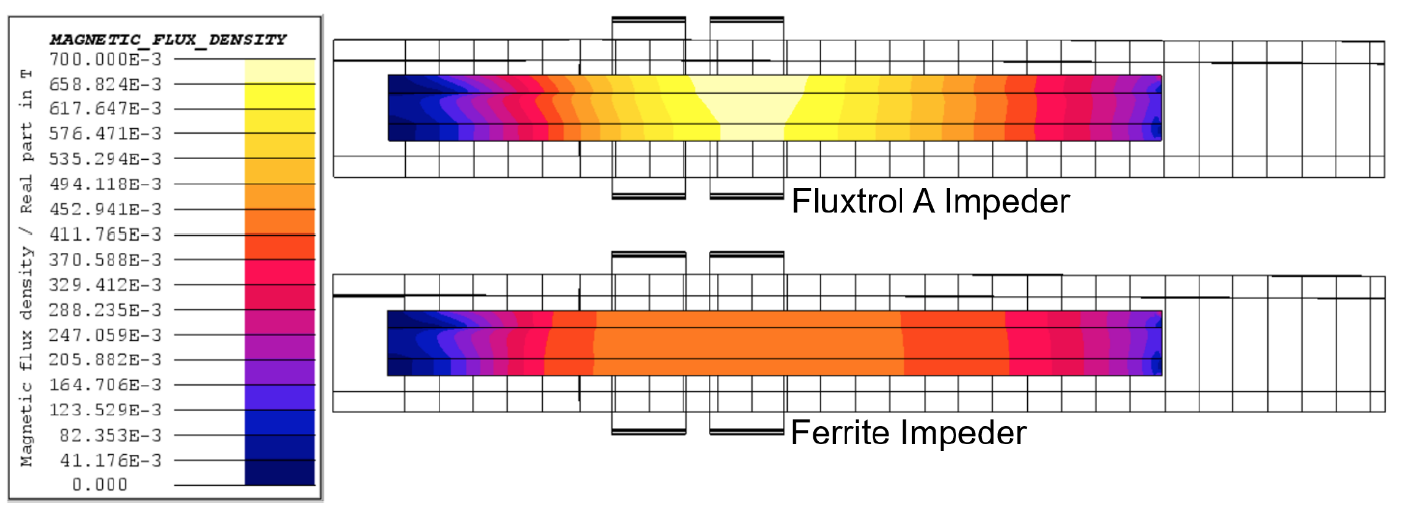
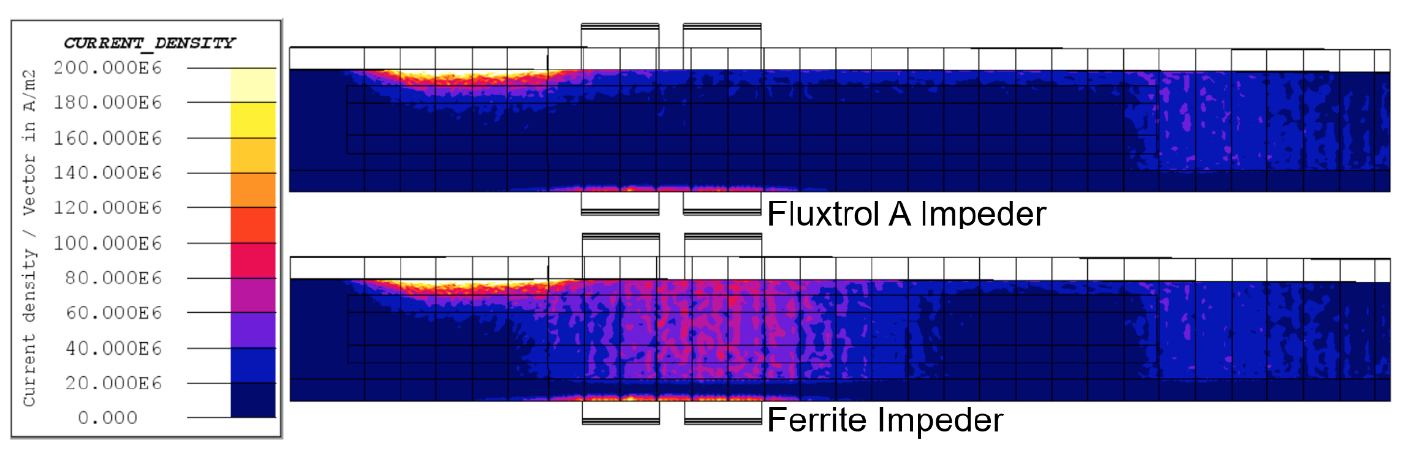
The Ferrite saturates at a magnetic flux density of ~0.41T, while the Fluxtrol A is well below its saturation flux density of 1.4T. Once the ferrite reaches saturation, some current begins to flow around the ID of the tube as opposed to along the edges of the weld vee. This internal current is the source of the difference in current between the two cases. The resulting current density distributions are shown in Figure 5. The main concentrations of current density are along the edge of the weld vee leading towards the apex. There is a drop in current density just past the end of the induction coil due to the transition from magnetic to non-magnetic in the tube. Once the outer layer is non-magnetic, the current flows much deeper in the part, resulting in lower current density on the edge of the vee. The current density along the edge of the weld vee going back towards the incoming material is smaller than going to the apex, but still significant.
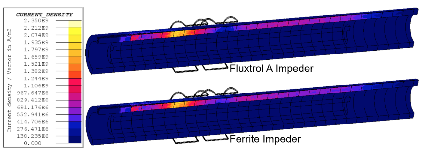
Figure 6 shows the distribution of current density on the tube in regions excluding the weld vee edges. In this view, it can be seen that some of the current is flowing along the ID of the tube in the area where the impeder was saturated. Also seen is the associated increased current density on the OD of the tube under the face of the coil. When using the Fluxtrol A Impeder, current does not return along the ID of the tube under the induction coil. This additional current density is how we can explain the higher current required using the ferrite impeder as compared to the Fluxtrol A impeder. Another band of current can be seen flowing on the ID of the tube after the end of the impeder. This is slightly higher with the Fluxtrol A impeder because almost no current returns on the tube ID under the inductor as it does with the saturated ferrite impeder.
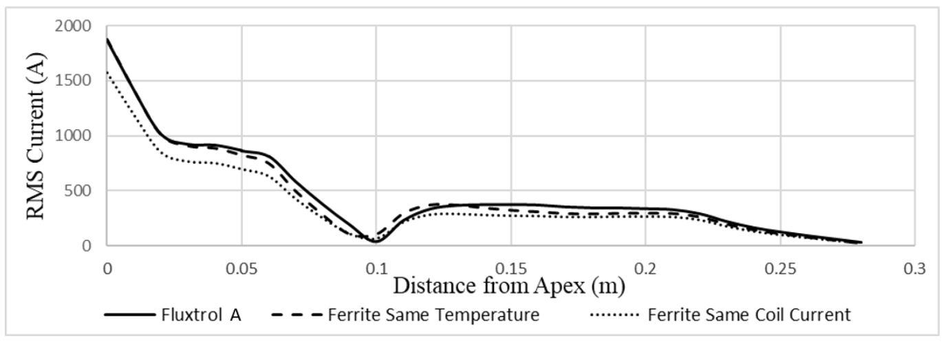
A plot of axial current versus position along the edge of the weld vee is shown in Figure 7 for three cases: the Fluxtrol A Impeder, the Ferrite Impeder at the same weld temperature, and the Ferrite Impeder at the same coil current. The current along the weld vee is maximum at the apex, dropping to near zero under the coil and rising to a lower level of current behind the coil which again returns to zero after the end of the impeder.
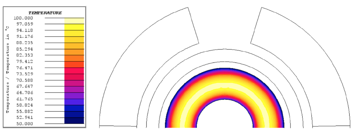
While the Fluxtrol A has greater saturation flux density than the ferrite and can better control the field, it must have proper water cooling to ensure impeder longevity. This is not an issue of temperature dependent saturation flux density, but rather that the material can begin to degrade due to exposure to elevated temperatures. To ensure proper continuous use, a maximum operating temperature of 250°C should not be exceeded within the impeder. As loading and losses are non-uniform, proper water cooling needs to be achieved in the most heavily loaded area under the second turn of the inductor. Based on the loading seen above, losses in the Fluxtrol A impeder in this area would be ~280MW/m^3 at 0.7T and 200kHz [12]. A quick thermal model was run to find the steady state temperature of the Fluxtrol A impeder under these conditions assuming a cooling water inlet of 60PSI at 30°C. The result can be seen below in Figure 8, showing that the area with the highest loading in the Fluxtrol A impeder can be cooled given these conditions.
Conclusions
For tube welding applications where the ferrite impeder cores are experiencing some degree of magnetic saturation, it has been found that SMCs have superior material properties and are able to improve the performance of induction tube welding systems. This is a common occurrence on systems where there is either a small diameter tube, heavy-walled tube, or a combination of both being welded. The greater saturation flux densities of SMCs allow for better control of ID tube current in these highly loaded systems compared to ferrites. The most notable improvements when switching from ferrite to Fluxtrol A are a reduction in required inductor current and in required system power for the same welding speed. For some extreme cases, a significant improvement in component quality can be achieved if there is excessive heating in the areas of the tube not near the edges of the weld vee. Other than improving overall process efficiency, this benefits production in improved coil life, reduced heating of the rolls, decreased downtime and increased line speeds using existing power supplies.
A new hybrid model for the efficient study and optimization of induction tube welding was proposed using loosely coupled 3D electromagnetic and 2D coupled magnetic and thermal models with motion. A case study of a 40 mm diameter tube with 6 mm wall thickness was used to demonstrate the model and make a comparison between ferrites and Fluxtrol A as impeder cores. The results show a 25% reduction in coil current and an 11% reduction in coil head power when switching from ferrites to Fluxtrol A. It is expected, that the total system power reduction would be close to 25% for these conditions in the field due to the benefits of lower coil current on losses in coil leads, heat station and power supplying components. The improvements are consistent with the authors experience in various tube welding trials.
Work is currently underway to validate the new modelling technique and the performance improvements of SMCs in these applications. Trials in real tube welding mills on various tube sizes, production rates and impeder designs are planned during 2019. Detailed data will be taken on the electrical parameters of the system, process temperatures and other production details and compared to the models. Updates to the models will be made based upon the field data and presented at future events.
In parallel with the model validation, additional work is being done to improve the model. Plans for 2019 are to add an external magnetic flux controller (bridge) to both the 2D and 3D models, fine tuning the 2-D simulation to consider variation in magnetic permeability in the length of the impeder and adding conductive components of the impeder assembly to the model. This will allow for more accurate depictions of the temperature distribution, as well as a study of how to improve weld system performance with appropriate magnetic circuit design.
References
[1] Goldstein, R.C. (2014). Magnetic Flux Controllers in Induction Heating and Melting. ASM Handbook Volume 4C, 633-645.
[2] Nemkov, V. (2008). Magnetic Flux Guide for Continuous High Frequency Welding of Closed Profiles. US Patent Application, US20080308550A1.
[3] Asperheim, J.I., et. al. (1998). Temperature Distribution in Cross-Section of the Weld Vee. Tube International, November 1998.
[4] Asperheim, J.I., et. al. (2000). Temperature Evaluation of Weld Vee Geometry and Performance. Tube International, 19, 497-502.
[5] Nikanorov, A., et. al. (2015). Numerical Simulation and Investigation of High Frequency Tube Welding Process. Applied Mechanics and Materials, 698, 245-250
[6] Das, P., Asperheim, J.I., et. al. (2017). Simulation of temperature profile in longitudinal welded tubes during High-Frequency Induction (HFI) welding. ASM HTS Conference, 2017
[7] Frame, L.D. (2017). Aspects of Precise Heat Input Control for High Frequency Welding. ASM HTS Conference, 2017
[8] Lupi, S., et. al. (1992). Induction Heating Industrial Applications. UIE, “Induction Heating” working group, 73
[9] Scott, P.F. (2014). Key Parameters of High Frequency Welding. A Thermatool Corp. Publication, https://thermatool.com/resources/technical-papers/
[10] Andrus, M., Mitchell, G. (2019). Discussions on the topic of Tube Welding Systems. EFD Induction Inc.
[11] EHE Consumables. (2019). Product Catalog. EFD Induction Group
[12] P. Vaishnava, R. Goldstein, (2019), Magnetic Core Loss Behavior at High Magnetic Fields in Magnetic Materials, HES 2019 Conference, Padua, IT.
If you have more questions, require service or just need general information, we are here to help.
Our knowledgeable Customer Service team is available during business hours to answer your questions in regard to Fluxtrol product, pricing, ordering and other information. If you have technical questions about induction heating, material properties, our engineering and educational services, please contact our experts by phone, e-mail or mail.
Fluxtrol Inc.
1388 Atlantic Boulevard,
Auburn Hills, MI 48326
Telephone: +1-800-224-5522
Outside USA: 1-248-393-2000
FAX: +1-248-393-0277
Related Topics
- Magnetic Core Loss Behavior at High Fields in Magnetic Materials
- Striation Effect in Induction Heating: Myths and Reality
- Simulation of Induction System for Brazing of Squirrel Cage Rotor
- Magnetic Flux Control in Induction Installations
- Recent Design and Operational Developments of Cold Wall Induction Melting Crucibles for Reactive Metals Processing
- Modeling and Optimization of Cold Crucible Furnaces for Melting Metals
- Modeling Stress and Distortion of Full-Float Truck Axle During Induction Hardening Process
- Temperature Prediction and Thermal Management for Composite Magnetic Controllers of Induction Coils
- Design of Induction Coil For Generating Magnetic Field For Cancer Hyperthermia Research