Toll Free


Information
Authors: Bernd-Arno Behrens, Robert Goldstein, David Guisbert, Deniz Duran
Location/Venue: IFHTSE TPIM 18 Spartanburg, South Carolina
Download Full Paper
Download Presentation PDF
Abstract
Bi-material machine components are fabricated usually by joining two individual components which are already given their near-final or final form. These are then put into operation either directly or upon a finishing process. Contrary to that, researchers of the Collaborative Research Centre “CRC 1153” Tailored Forming are investigating novel process chains, in which different materials are joined in the first step and then subjected to further processing, i.e., forming, machining and heat treatment. By this means, the joining zone properties, which are adversely affected due to the joining process, can be treated and improved via thermomechanical processing during forming. On the other hand, process-specific challenges arise especially for workpieces consisting of dissimilar materials, i.e., steel and aluminum. In order to obtain a favorable flow behavior of the materials in the vicinity of the joining zone, a near step-function temperature distribution in the bi-material billet is desirable. Induction heating is viewed as the most promising method to be used for this purpose.
At the Heat Treat 2017 conferences, a paper was presented which discussed the strategy for thermomechanical processing and the modeling of the first concept for the induction heating process [1]. The current study builds on the previous paper and presents the modeling of the forming process along with the analysis of the first prototype samples formed using the technology. A metallurgical evaluation of the joining zone properties of the prototype components after thermomechanical processing will be presented. Additional considerations will be given on how to further improve the process and move towards a production capable process.
Introduction
Tailored blanks combine various sheet metals and can differ locally in terms of sheet thicknesses/geometries or material types/properties. This technology utilizes the joining of different sheets, for instance via laser welding. Forming processes are carried out in the subsequent steps, whilst the workpieces being already in the joined state. Materials’ different responses to forming and the reliability of the joining are the two main challenges, the latter being decisive on the final product property. After being discovered by the steel producer ThyssenKrupp in 1985, the technology gained attention, especially in the automotive industry, and its market share has been continuously expanded. Today, many important carbody components, such as front rails, B-pillars and reinforcements, are fabricated from tailored blanks [2].
The high potential of lightweighting by merging dissimilar materials in a single machine element urges researchers to employ the concept of tailored blanks in the bulk forming industry. But, the studies in the field gathered mainly around the idea of generating the coalescence between different materials during the plastic deformation step. This approach eliminates the need of a particular joining process as distinct from the tailored blanks concept. Instead, joining and forming are expected to take place simultaneously during forming. Numerous studies that utilize this concept have been conducted.
Joining of dissimilar materials by cold extrusion was studied by Wagener and Haats [3]. It was shown that the bond strength increases with the degree of plastic deformation applied during extrusion. Kazanowski et al. [4] investigated forward rod extrusion of two different coaxially combined aluminum alloys at elevated temperatures. Some imperfections, such as local separations and inhomogeneous microstructure were discovered at the joining interface. Rhee et al. [5] studied forming of aluminum-copper billets by hot hydrostatic extrusion process by using low-density polyethylene as the forming media. Optimal processing parameters were sought based on the microstructural analyses of the formed workpieces. Upsetting of steel-copper and steel-aluminum tubular billets was analyzed by Schlemmer and Osman [6] with the intention of achieving complex forms via preferential induction heating. Different flow modes during upsetting were observed and associated with the billet geometry and heating parameters. It was shown by Awiszus et al. [7] that a metallurgical joint between magnesium and steel can be created by means of side impact extrusion. Cold upsetting of coaxially assembled steel-steel billets were studied by Essa et al. [8]. The gaps occurring at the joining interface are associated with the billets’ initial geometry. Hot forging of steel-steel billets was studied by Behrens et al [9]. A low-cost structural steel (S355J) and an alloyed steel (42CrMo4) were successively arranged by spot welding and forged together at 1250 °C. Tensile tests applied on the formed specimens showed that the strength of the joining is higher than the strength of S355J.
Some other studies were also found which utilize a similar concept to the tailored blanks. All these have in common a dedicated joining process to manufacture hybrid forging billets before the forming process takes place. By this means, a metallurgical joint is created between different materials. Although this concept adds an additional step to the process chain, it is possible to treat and improve the bonding properties of the metallurgical joint by deformation processing.
Friction welded similar and dissimilar material pairs were forged and characterized by Domblesky et al. [10]. They found that the formability of the similar material pairs in the hot forging regime is comparable to that of monolithic workpieces. For dissimilar material pairs, plastic deformation was found to be concentrated in the material exhibiting lower flow stresses. Upsetting of cladded workpieces at elevated temperatures was investigated by Wang et al. [11]. A variant of stainless steel (SAE 316L) was cladded on the lateral surface of cylindrical billet made of a plain carbon steel (C15) to prepare the forging billets. Formability was evaluated both experimentally and numerically, and related with the processing conditions. Different deposition welded and friction welded hybrid billets were upset isothermally by a thermomechanical simulator by Frischkorn et al. [12]. In a follow-up study, Behrens et al. [13] carried out cross wedge rolling with similar hybrid billets. In both studies, high plastic strains could be reached without observing any damage or disjunction of the two materials.
With the motivation of extending component functionality by utilizing appropriate material at the appropriate location, a university based fundamental research project was established at the Leibniz Universität Hannover. “Tailored Forming” aims to understand the complete process chain to manufacture hybrid high performance components. The process chain for a hybrid stepped shaft fabrication is illustrated in Figure 1. The first step is the joining of two different materials by friction welding to manufacture hybrid forging billets. In the next step, impact extrusion is carried out which is essential to improve the joining properties by thermomechanical processing. This is followed by heat treatment and machining. There are also project fields engaged in design, simulation, service life assessment and quality control [14].
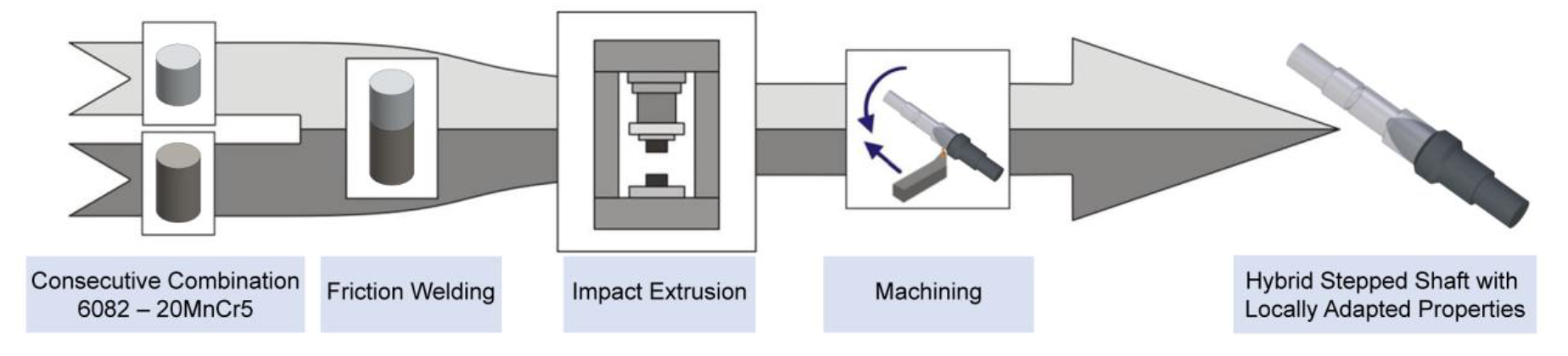
Figure 1: “Tailored Forming” process chain for a hybrid stepped shaft [1]
The authors have investigated the feasibility of thermal processing of bi-material billets by modeling and also experimentation [1]. Induction heating simulations of bimaterial billets were conducted using ELTA™ and Flux™ 2D software. The steel/aluminum bi-material billets were designed and prepared for temperature measurement during induction heating experiments. An experimental setup was built along with some dedicated components. Experimental temperature readings were compared with the simulation results and the findings were discussed.
The current study builds on the previous paper and presents the modeling of the forming process along with the analysis of the prototype samples formed using the technology. A metallurgical evaluation of the joining zone after thermomechanical processing will be made. Additional considerations will be given on how to further improve the process and increase the joining zone deformation to lead to improved properties. These considerations will include the presentation on a new semi-submerged heating concept along with forming tooling improvements in order to move towards a production capable process.
2. Experimental Setup
In this section, the details of the used experimental equipment are explained in four subsections:
2.1 Materials
The hybrid workpieces used in the study combine a case hardening steel (DIN 20MnCr5) with a wrought aluminum alloy (EN AW-6082). These materials are often utilized separately in the forging industry. 20MnCr5 is usually case hardened to increase its wear resistance whilst providing good core toughness. Camshafts, gears, piston bolts and many other Figure 1: “Tailored Forming” process chain for a hybrid stepped shaft [1] vehicular components are made of this type of steel. 6082 is a variant of 6000 series alloys whose main alloying elements are magnesium and silicon. This material is usually solution heat treated and artificially aged (T6) and offers great toughness in addition to its good strength to weight ratio. Many axle components, such as control arms or knuckles, as well as drive shaft components and housings are made of 6082.
2.2. Friction Welding
Rotary friction welding process is used for the manufacturing of steel-aluminum hybrid forging billets. This solid-state welding process enables the joining of both similar and also dissimilar material combinations consecutively. The heat is generated via mechanical rubbing of the welding surfaces until they plasticize. Then the workpieces are pressed together under an axial force in order to create the bond.
As far as the steel-aluminum joints are concerned, the main disadvantage is the divergent plastic flow behavior of the materials. In general, steels’ flow stresses are considerably higher than those of aluminum alloys’. Thus, plasticization occurs only at the aluminum side whilst steel acts almost rigid during friction welding. This phenomenon hinders the microstructural evolution of steel through dynamic recrystallization, which is reported to be the primary grain refinement mechanism in friction welding [15]. On the other hand, relatively less heat input and short process times are favorable because of inhibiting the growth of intermetallic compounds at the welding interface. These intermetallics are characterized by their brittle nature and can significantly reduce the bond strength in case that they grow above a certain thickness.
Prior to friction welding, the end faces of both sides were face-turned to obtain clean and plane-parallel welding surfaces. Then the welding operation was carried out with the main important parameters given in Table 1. Forging phase took place in two consecutive two-seconds lasting steps in which the forging pressure was increased from 150 to 170 MPa. After welding, the flash was trimmed which solely occurred on the aluminum side. The welded workpieces were finally cut off to their final dimensions to obtain hybrid forging billets.
Table 1. Main process parameters used in the friction welding of aluminum and steel
| Friction shortening | Friction pressure | Forging time | Forging pressure |
|---|---|---|---|
| 3.5 mm | 130 MPa | 2 / 2 s | 150 / 170 MPa |
2.3 Induction Heating
A mid-frequency generator (TRUMPF TruHeat MF 3040) was used in the heating experiments whose output voltage was set to 300 V. It can deliver a maximum power of 40 kW and the output rate can be assigned. The heating rig is positioned inside an automated forging cell. A water-cooled induction coil with rectangular profile was used as the inductor. Wound profile was wrapped with a fire-resistant fabric and a ceramic tube was inserted into the coil for centered positioning of the workpiece. A data acquisition system with temperature input module is available by the heating rig which allows for in-situ temperature measurements during heating experiments.
An illustration of the experimental setup is shown in Figure 2. The hybrid billet was translated with an axial offset inside the coil until the joining line meets the top turn of the coil. The intention was to balance the flow stresses of the two materials which is essential to plastically deform both materials by the joining zone. The target steel temperature was chosen to be between 900 and 1000 °C, whereas aluminum should be kept as close as possible to room temperature. A copper shunt was placed in the inductor, beneath the steel side in order to prevent the overheating of steel end due to electromagnetic end effect.
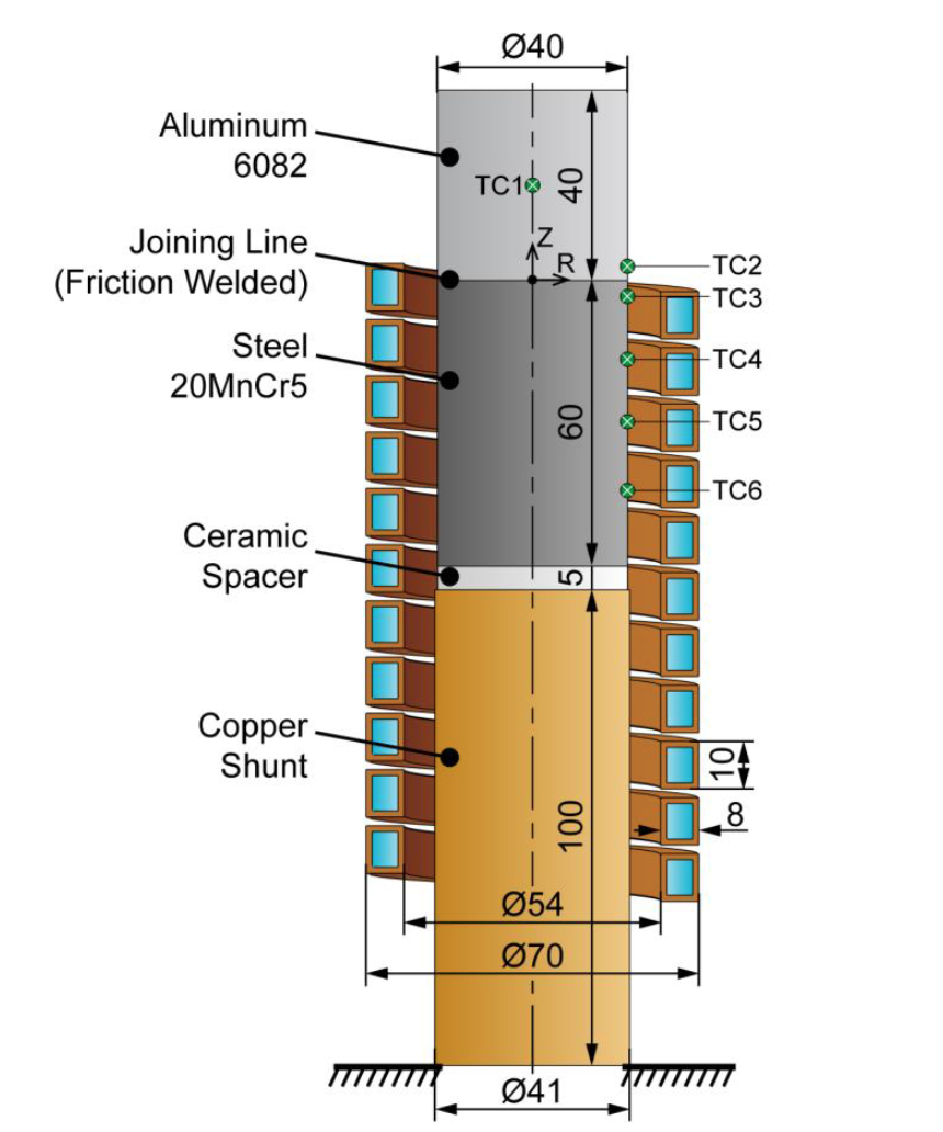
Figure 2: Experimental setup for induction heating [1]
Temperature measurements were carried out by using K-type thermocouples (TC). In total, six TCs were attached on the workpiece at different locations. TC1 was embedded in the center of aluminum with a distance of 20 mm from the joining line (TC1). The other five thermocouples were mechanically attached onto the lateral surface. TC2 was placed with 2.5 mm axial offset from the joining line on the aluminum. TC3, TC4, TC5 and TC6 were placed on the steel with distances of 2.5, 15, 30 and 45 mm, respectively. A detailed layout of the thermocouples can be found in [1].
2.4. Impact Extrusion
Impact extrusion process was carried out in an automated forging cell, with a screw press which has a gross energy of 40 kJ. The heated billets were transferred from the induction heating rig and placed in the forming die by using an industrial robot. After the stroke, the formed workpiece is ejected from the die and removed manually by using forging tongs.
A sectional view of the used tooling system for hybrid forward rod extrusion process is shown in Figure 3. The billets are laid in the forming die, aluminum being below steel. Using a punch, hybrid billets are compressed through the die shoulder as they become smaller in cross-sectional area and longer in length. During forming, the joining zone passes through the die shoulder entirely where main plastic deformation takes place.
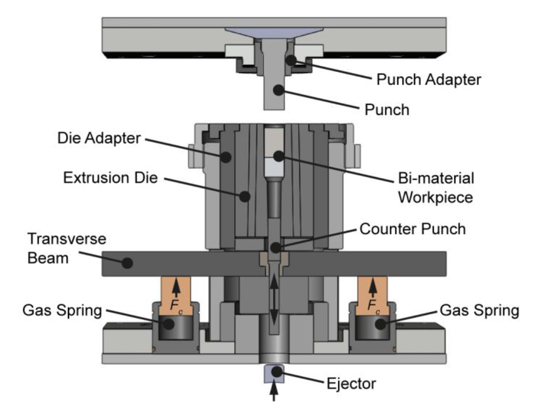
Figure 3: Impact extrusion tooling with counter force superposition mechanism [1]
Although being a compressive stress dominated forming process, tensile stresses may also occur in the plastic deformation zone during forward rod extrusion. This may lead to emanation of cracks and even separation at the joining interface. In order to control the stress state at the joining interface, a counter force superposition mechanism was designed and situated below the forming die. It consists of a counter punch, a transverse beam, and two laterally placed heavy-duty gas springs. The magnitude of the counter force can be changed easily by adjusting the filling pressure of the gas springs. A maximum counter force of 110 kN can be applied via this system.
For the purpose of die preheating, six cartridge heaters can be engaged, each being 500 W. These are assembled into die adapter and controlled precisely via a closed loop temperature control unit. The die side was preheated to 150 °C prior to forming experiments.
3. Numerical Modeling
Flux™ 2D, an electromagnetic and thermal analysis software based on the finite element method, was used to set up the numerical model of induction heating processes. Magneto-thermal and thermo-physical properties of the materials were imported from its material library. Ideal thermal and electrical contact was defined for the interfaces between the solid materials, namely aluminum-steel, steel-ceramic and ceramic-copper. Between air-aluminum and air-steel, a convection coefficient of 10 W/(m^2)K and an emissivity of 0.7 were assigned. Based on the inductance and the possible losses of the system, the applied current was manipulated to hold the generator output approximately at 25 kW. Operating frequency was defined as 15 kHz.
Steel surface reached 1000 °C after an inductive heating time of 20 s. It was assumed that if the heating proceeds above 1000 °C steel temperatures, it might lead to overheating of aluminum and thus a drastic decrease of its flow stresses. Therefore, induction was terminated at this point and a pure thermal analysis for an additional time of 10 s was conducted in order to visualize the balancing of temperature gradients in the hybrid billet. These phases were designated as induction heating (t = 0–20 s) and natural cooling (t = 20–30 s), respectively.
For the simulation of the metal forming process, Marc™ was used which is a general-purpose nonlinear finite element analysis software. Flow curves of aluminum and steel were determined through compression tests at different strain rates and temperatures [16]. Thermo-physical properties of the materials were calculated with the CALPHAD method as functions of temperature [17]. Calculated material properties were implemented in Marc in tabular format. Another essential matter is the transfer of the temperature field from Flux to Marc. To this end, a user subroutine was written which reads the temperature values exported from Flux with respect to their coordinates and assigns them to the nodes of the new Marc mesh by means of a coordinate searching algorithm. Aluminum and steel were modelled as deformable bodies, whereas dies were treated as rigid bodies. The welding interface was represented with glued contact condition that means a separation between the bodies would not be allowed regardless of the stress state. Due to severe deformation, remeshing option was activated.
4. Results and Discussion
The surface temperatures at the middle section of steel was found to be around 1000 °C after 20 s of heating, when the generator power output rate was set to 65%. Utilizing more power would result in excessive heating of the surface and thus inhomogeneous through-thickness temperature distribution in the steel. Temperature values were exported from Flux, from the material points corresponding to thermocouples’ locations. These were compared with the experimental readings as shown in Figure 4.

Figure 4: Comparison between experimental temperature readings and simulation results [1]
Trends of the curves agree both in heating and in post-heating phases. Temperature values were also found to be in conformity with each other, although minor discrepancies exist. These were justified with the following arguments:
- The same value for convection coefficient (10 W/(m^2)K) was assumed between steel-air and aluminum-air. In fact, these should not be identical since steel remains inside the coil during heating and aluminum is exposed to free air.
- A uniform emissivity value (0.7) was assigned for steel. However, steel glows at elevated temperatures and thus, its emissivity changes which were not considered in the analysis.
- Ideal contact was assumed for the friction welded interface between aluminum and steel. Although being in close proximity, the real temperature difference between TC2 and TC3 is greater than the simulative predictions. This might indicate that the joining interface actually behaves like a reduced conductivity layer between the two materials. In this case, the assumption of ideal contact might be misleading. Thorough investigations are essential to understand this phenomenon.
The handling of heated hybrid billets from the induction heating rig to the forming die was carried out by an industrial robot. The time from the end of heating to the onset of deformation was approximately 5 seconds. In Figure 5, the temperature profiles of the surface and the center are shown after heating (continuous line) and before forming (dashed line). During this time, high temperature gradients in the steel disappear and a balancing between the surface and the center takes place. The temperature difference between aluminum’s surface and center is not significant due to its superior thermal conductivity. It should be noted that a 10 mm portion (-10 < Z < 0) of the steel is extruded and the rest end (-60 < Z < -10) only expands laterally and fills the die, cf. Figure 2. For the portion to be extruded, the heat could be transmitted to the center fairly well before forming. Surface temperatures by the joining line were maintained at around 350 °C during transfer, whilst center temperatures increase about 50 °C.
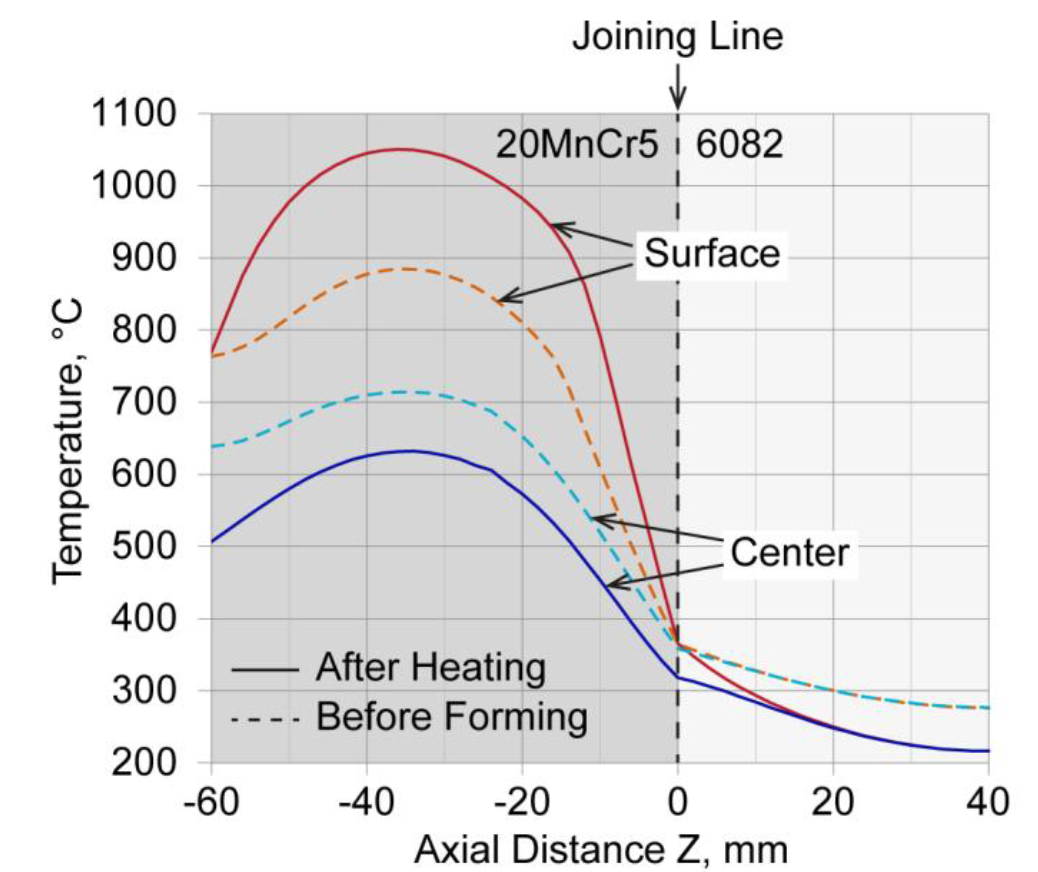
Figure 5: Temperature profiles along surface and centerline after heating and before forming (simulation finding) [1]
Extruded workpieces were halved by using an abrasive cutter in order to reveal the development of the joining line. A comparison between the Marc simulation result and experiment is given in Figure 6. The geometrical evolution of the joining line could be predicted accurately. Colored contours represent the temperature distribution. The press speed was measured to be around 500 mm/s at the onset of the deformation. This means that the deformation stroke was completed within some-tenths of a second. Therefore, the heat losses to the die were not substantial during forming. On the other hand, the influence of the frictional heat generation at the very surface is visible. Another important issue is the risk of melting of the aluminum in case of overheating. Melting point of 6082 was reported to be 555 °C. According to the simulation results, there is no risk of local melting of the aluminum by the joining zone during both forming and post-forming phases. Temperature values along the joining line barely exceed 500 °C. Extruded workpieces were visually inspected and no local melting at the surface was observed. The flow stress inhomogeneity at the material transition zone results in an insufficient plastic straining of steel. Thus, steel does not penetrate aluminum and the joining line remains rather flat, particularly at the workpiece center.
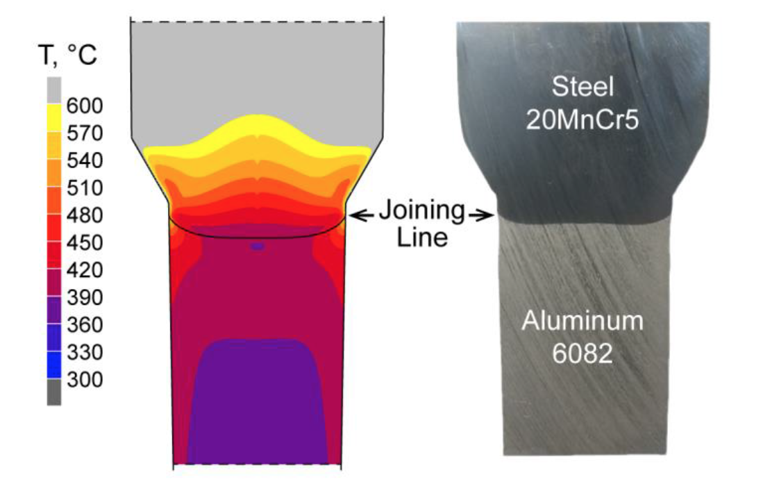
Figure 6: Development of the joining line: simulation result with temperature contours on the left, experimental result on the right
After the initial sectioning, the samples were polished for more in-depth metallurgical analysis. After polishing, the samples were etched to reveal the joining line. Etching was first done on the steel, using a 2 percent Nital etchant – the entire sample was immersed and swabbed for approximately 15 seconds. This was followed by rinsing in water and then drying. The specimen was then etched for microstructure of the aluminum by immersing in a 0.5 percent Hydrofluoric etchant – this time the entire specimen was submerged, but it was not swabbed. This was followed again by water rinsing and drying. Photographs were taken of the overall joining zone, center, the left edge and the right edge, respectively (Figure 7).

Figure 7: Micro photographs taken from: (a) overall joining zone, (b) center, (c) left edge, (d) right edge
The samples revealed some defects in the part that was studied. It was observed that there was a relatively large separation of the two materials in the middle of the sample. The separation is at and adjacent to the interface. It is unclear if the separation occurred due to the thermomechanical forming process or was present in the sample after the welding process. The relative velocity during the friction welding converges to zero at the central region which can explain the absence of bonding in this particular case. Material defects have also been observed in some of the friction welded samples. Cracks were also found in the aluminum at the outer diameter – away from the interface. The cracks at the outer diameter were not apparent in the as-polished condition, but they are revealed after etching.
Under higher magnification of the areas without cracks, we do not see the intermetallic phases reported in other research reports. They speak in terms of thickness levels between 0.5 and 3 microns. When looking at the 100X objective photos (approximately 830 X magnification), it shows a 10 micron bar, so we are certainly not seeing a distinct intermetallic phase at the interface. Under very high magnification, it is difficult to focus simultaneously on all three material zones (steel, joining zone, and aluminum), so three separate photos are used to show the area (Figure 8). This is associated with the fact that the materials show different responses to the abrasive processes (grinding followed by polishing) in the metallographic specimen preparation phase.
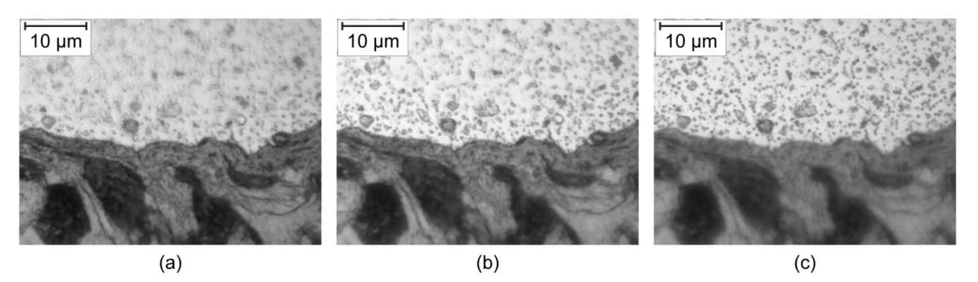
Figure 8: Microstructural images of the joining zone under high magnification (captured from ½ radius): (a) steel in focus, (b) joining zone in focus, (c) aluminum in focus
It is important to note that the area of large separation in the center is located in the area of minimal deformation of the material. The amount of plastic straining of steel can be increased provided that the temperature gradients along the material transition become higher in order to match the materials’ flow stresses. To this end, induction heating process can be improved by changing the coil design. More importantly, heat should be extracted from aluminum effectively during induction heating. A new induction heating concept is therefore put forward as depicted in Figure 9. The hybrid billet is submerged in a water tank until the joining line, aluminum being in the water. For local heating of steel, a three turn induction coil is used. To improve the efficiency of the coil and to prevent undesired heating of aluminum, a magnetic flux concentrator (Ferrotron 559H of Fluxtrol™) is positioned around the coil. For precise positioning of the billet, a ring spacer made of copper is placed at the bottom of the tank.
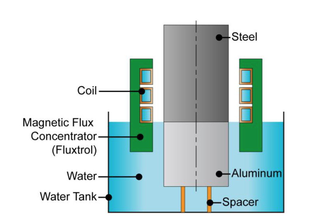
Figure 9: Semi-submerged induction heating concept
The boiling curve of water exhibits a highly nonlinear behavior. The domain of interest for the investigated case is between room temperature and 200 °C. In this domain, the curve makes a peak which is referred to as critical heat flux. The target temperature of aluminum is around the temperature corresponding to the critical heat flux. That means maximum possible heat can be transferred from aluminum to water by designing induction heating process accordingly with the aid of numerical simulation. Once the induction is terminated, initial temperature of aluminum will be lower which will help to survive higher temperature gradients in the steel during transfer. Surface of aluminum will be colder than its center, but these will also be balanced during transfer due to aluminum’s high thermal conductivity.
Electromagnetic and thermal modeling using Flux was conducted to verify the principle. A non-linear heat transfer coefficient was applied to the surface of the aluminum portion of the bi-metal billet. To make a good comparison to earlier models of the process, ideal thermal contact between the materials was assumed. The sample was heated to a maximum surface temperature in the steel of 1100–1200 °C, and then power was profiled to maintain a constant temperature while heat conducted to the core of the sample. A quasi-stationary distribution of temperature was achieved at approximately 60 seconds of heating time as losses due to conduction through the steel and to the aluminum offset additional heat applied near the surface of the billet. After 60 seconds, power was turned off and the heat transfer on the surface of the aluminum was modified to free convection to air to simulate the billet transfer from heating coil to the press. Models were run for an additional 6 seconds. After transportation, the isotherms of temperature are quite straight, which should lead to an improved deformation profile along the bond line. The color shades of temperature distribution are shown in Figure 10.
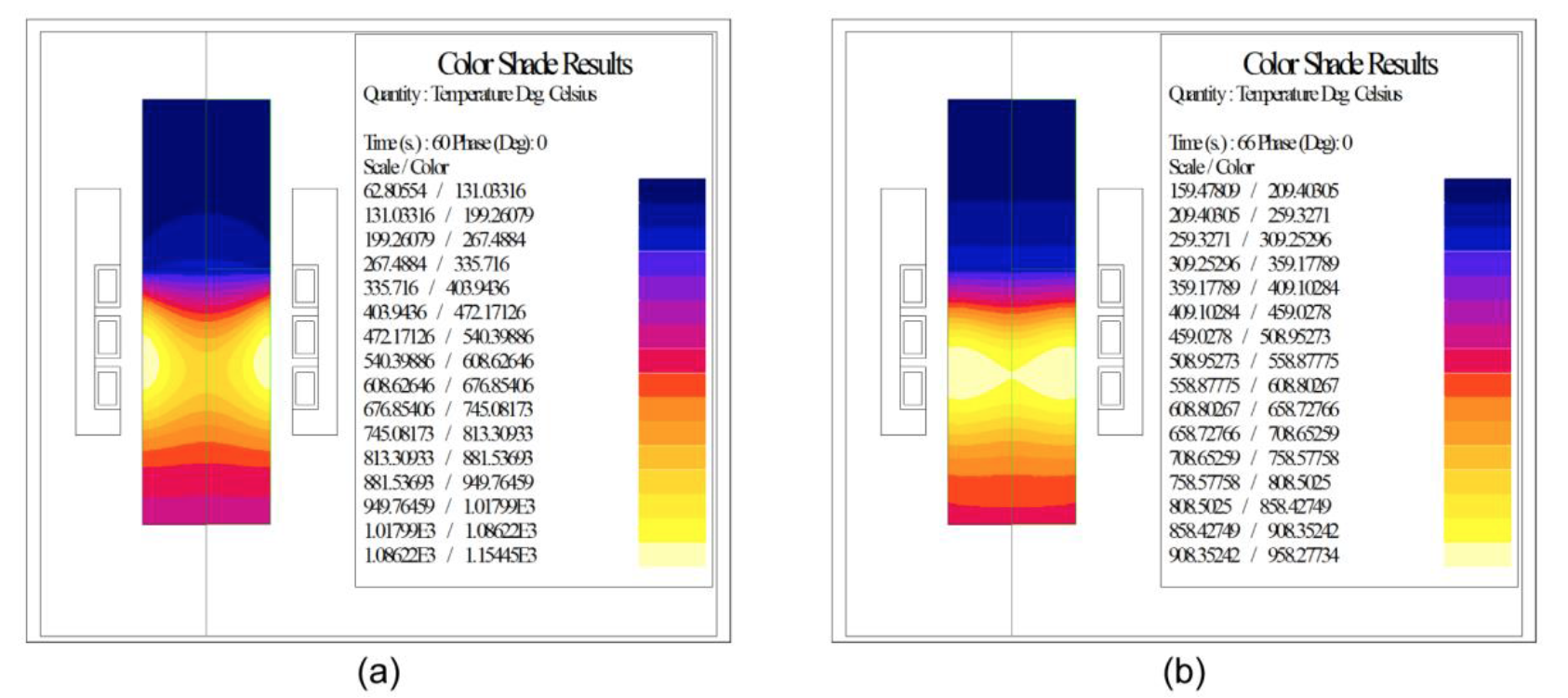
Figure 10: Simulation results of the semi-submerged induction heating concept; color shades show temperature distributions: (a) after induction heating (t=60 s), (b) before forming (t=66 s)
To better understand the distribution, the temperature profiles along the centerline and surface of the billet were plotted for the near joining zone of the hybrid billet at the end of heating (60 s) and after transportation (66 s) in Figure 11. Compared to the results shown in Figure 5, core temperatures are much warmer in the near joining zone while maintaining lower aluminum temperatures which should result in improved material flow characteristics. Keeping in mind that the thermal contact in the samples is likely non-ideal, the real temperature distributions will likely be significantly more favorable than predicted by these models.

Figure 11: Temperature profiles near the joining line after semi-submerged induction heating and before forming (simulation finding)
5. Conclusion and Outlook
This study has presented the tailored forming technology with an exemplary product: a hybrid stepped shaft. The forging billets have been produced by friction welding aluminum (EN AW-6082) and steel (DIN 20MnCr5) rods which is the initial step in the process chain. The requirements for thermal and thermomechanical processing of hybrid billets have been manifested. Preliminary studies have shown that a successful forming operation requires a non-homogeneous temperature distribution in the workpiece. Induction heating has been used as the heating source for the thermal process prior to impact extrusion. Using this method, preforms of a hybrid stepped shaft have been produced.
A technique has been developed for sample preparation prior to metallurgical evaluation of the workpieces. A detailed metallurgical evaluation of the samples revealed separation between the materials near the joining line in the region near the center of the billet. The separation included defects on the joining line, but also separations in the aluminum itself. It is unclear if the separation was an artifact of the friction welding process, the thermomechanical process, or the post forming sample preparation. Comparisons of computer modeling and experimental studies showed evidence which could be indicative of non-optimal thermal contact between the bodies. This could be indicative of this separation being present prior to inductive heating.
Additional studies should be conducted on a larger population of hybrid billets to determine the root cause of the defect. In addition, further studies on concepts for improved the friction welding process are being explored including improved joining line geometries in order to see if the incoming mechanical properties of the assembly can be improved prior to thermomechanical process.
The defects occurred in the central area of the billet where there was minimal material deformation which is meant to improve the properties of the bond. The temperature in the steel in the central region of the billet was below the desired temperature near the joining line and lower than the temperature of the outer regions of the sample. In addition, the aluminum temperatures were higher than desired, leading to sub-optimal material flow behavior.
Based upon the experimental results, a strategy was developed to improve temperature distribution in the hybrid billet. Calculations have already been made for the use of an improved inductor using a shorter induction coil, Fluxtrol magnetic flux controllers along with a semi-submerged heating concept. The direction of these concepts is to lower the aluminum temperatures, reduce the transient zone between steel and aluminum and reduce the radial gradients in the steel. Models of this process showed the possibility to significantly improve the thermal gradient in the bi-material billets, which should lead to improved material flow characteristics.
Further study will focus on extending the modeling capabilities on the new concept. Forming simulation will be conducted by using Marc software. The temperature distributions calculated by Flux 2D will be transferred to Marc as initial temperature condition for forming. To this end, a user subroutine has already been written and tested. A comprehensive material characterization study which is needed for the forming simulation has also been completed.
Also, it is understood that for this type of component, post forming selective heat treatment will likely be required. 20MnCr5 is a case hardening steel, which requires the addition of carbon via diffusion in order to achieve significant strength improvements. After joining to the aluminum, it will not be possible to perform traditional carburizing technology to this component, because the processing temperature exceeds the melting temperature of aluminum. Post forming heat treating on this steel could be achieved using the technology invented by Dr. Saveliy M. Gugel for submerged inductive hardening in a liquid active media [18]. In this technology, the component is submerged in a carbon rich liquid. Inductive heating is used selectively on the component to boil and then form a carbon rich vapor blanket over the region of the component that hardening is desired on. In adjacent aluminum regions, the cooling capacity of the liquid will be sufficient to prevent overheating of this region while the carbon is diffusing in the steel. After sufficient time, the power is turned off, the vapor blanket collapses and the liquid media quenches the treated region of the component to form a locally case hardened layer.
An alternative solution could be to use an induction hardenable steel prior to welding and forming. Due to the lower alloy content, the weldability of these steels tends to be better than case hardening steels and the price of the steel tends to be lower. Also, their hardenability tends to be much less, so a more rapid rate of heat extraction after the forming process would be possible. Additional modeling should be made on the complete manufacturing chain for alternative steel and aluminum alloy types to determine the best material combination for this application.
Acknowledgments
The results presented in this paper were obtained within the Collaborative Research Centre 1153 “Process chain to produce hybrid high performance components by Tailored Forming” in the subproject B3. The authors would like to thank the German Research Foundation (DFG) for the financial and organizational support of this project. The authors would also like to provide thanks to Fluxtrol Inc. and QA Metallurgical Services, Inc. for providing institutional support for the project.
References
[1] Goldstein, R. et al., “Role of Thermal Processing in Tailored Forming Technology for Manufacturing Multi-Material Components”, Heat Treat 2017: Proceedings of the 29th ASM Heat Treating Society Conference, October 24-26, (2017), Columbus, Ohio, USA.
[2] ThyssenKrupp Tailored Blanks GmbH, “Tailored Blanks Optimierte Bauteile aus Stahlblech”, Product Catalogue, Issue 10, (2004).
[3] Wagener, H.W. and Haats, J., “Pressure welding of corrosion resistant metals by cold extrusion”, Journal of Materials Processing Technology, 45–1, (1994), pp. 275-280.
[4] Kazanowski, P. et al., “Bi-metal rod extrusion–process and product optimization”, Materials Science and Engineering: A,369–1–2, (2004), pp. 170-180.
[5] Rhee, K.Y. et al., “Fabrication of aluminum/copper clad composite using hot hydrostatic extrusion process and its material characteristics”, Materials Science and Engineering: A, 384–1–2, (2004), pp. 70–76.
[6] Schlemmer, K.L. and Osman, F.H., “Differential heating forming of solid and bi-metallic hollow parts”, Journal of Materials Processing Technology, 162–163, (2005), pp. 564-569.
[7] Awiszus, B. et al., “Analyse des Querfließpressens als Analogieversuch zum Strangpressen unter besonderer Berücksichtigung der Verbundbildung zwischen Aluminium und Magnesium”, UTF Science, IV, (2009).
[8] Essa, K. et al., “Upsetting of bi-metallic ring billets”, Journal of Materials Processing Technology, 212–4, (2012), pp. 817-824.
[9] Behrens, B.–A. et al., “Basic study on the process combination of deposition welding and subsequent hot bulk forming”, Production Engineering, 7–6, (2013), pp. 585–591.
[10] Domblesky, J. et al., “Welded preforms for forging”, Journal of Materials Processing Technology, 171–1, (2006), pp. 141–149.
[11] Wang, J. et al., “Study of the hot forging of weld cladded work pieces using upsetting tests”, Journal of Materials Processing Technology, 214–2, (2014), pp. 365–379.
[12] Frischkorn, C. et al., “Investigation on a new process chain of deposition or friction welding and subsequent hot forging”, Materialwissenschaft und Werkstofftechnik, 44, (2013), pp. 783–789.
[13] Behrens, B.-A. et al., “Basic study on the process combination of deposition welding and subsequent hot bulk forming”, Production Engineering, 7–6, (2013),pp. 585–591.
[14] Behrens, B.-A. et al., “Fließpressen hybrider Halbzeuge”, wt Werkstattstechnik online, Volume 105, Issue 10, (2015), pp. 704-708.
[15] Xiong, J. et al., “Cellular automata simulation of dynamic recrystallization in rotary friction welding of pure copper”, Indian Journal of Engineering & Materials Sciences, Vol. 24, (2017), pp. 377-382.
[16] Behrens, B.-A. et al., “Importance of Material and Friction Characterisation for FE-aided Process Design of Hybrid Bevel Gears”, Proceedings of the 20th International ESAFORM Conference on Material Forming, April 26-28, (2017), Dublin, Ireland.
[17] Guo, Z. et al., “Modelling of materials properties and behaviour critical to casting simulation”, Materials Science and Engineering A, 413-414, (2005), pp. 465-469.
[18] Gugel, S.M., “Induction Carburizing – A Novel Cost Effective Environmentally Safe, Affordable Technology”, Phase II, Contract No. N00014-00-C-0560, “Furnish the necessary personnel and facilities to conduct research of the optimum treatment parameters of new Induction Carburizing Technology (LINCARBTM) in liquid active media (LAM) for special gears”, Final Technical Report No. N14-03/3, 06/30/2004, pp. 1-389.
If you have more questions, require service or just need general information, we are here to help.
Our knowledgeable Customer Service team is available during business hours to answer your questions in regard to Fluxtrol product, pricing, ordering and other information. If you have technical questions about induction heating, material properties, our engineering and educational services, please contact our experts by phone, e-mail or mail.
Fluxtrol Inc.
1388 Atlantic Boulevard,
Auburn Hills, MI 48326
Telephone: +1-800-224-5522
Outside USA: 1-248-393-2000
FAX: +1-248-393-0277