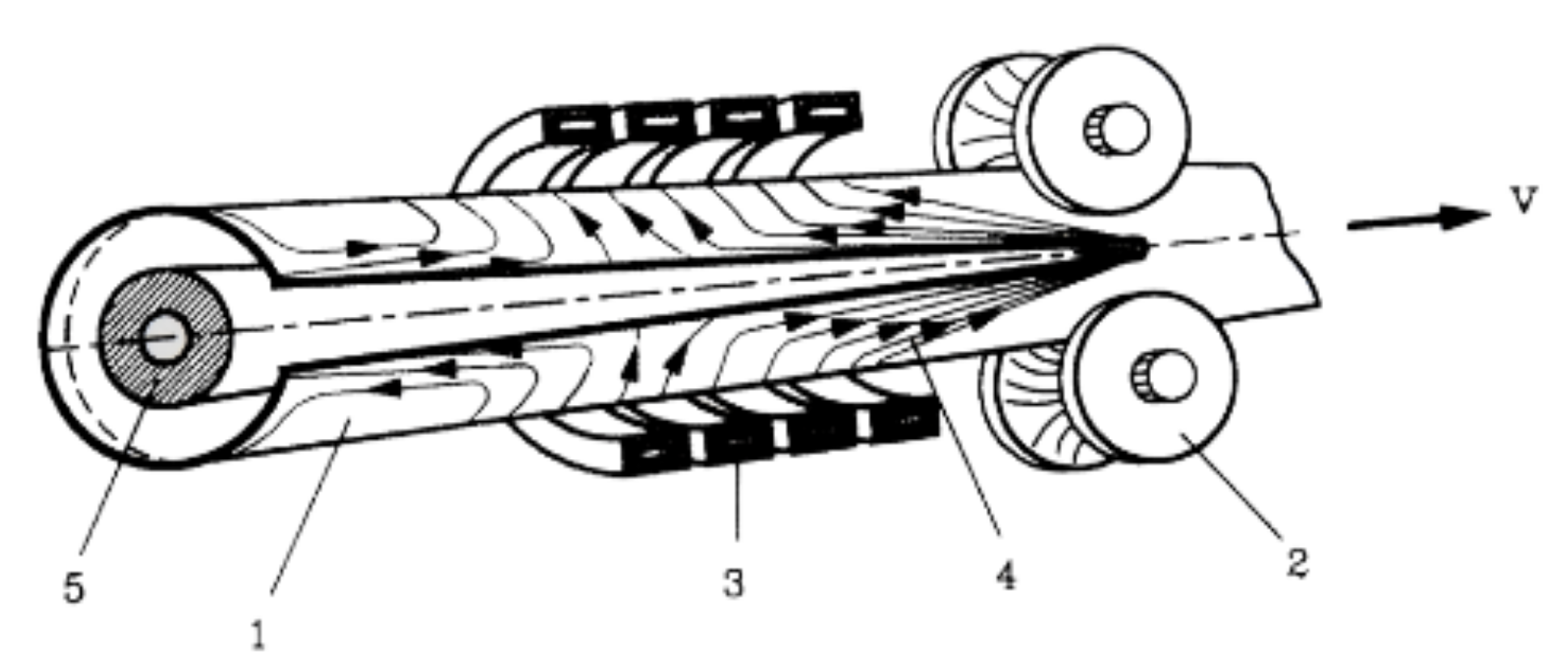
Induction tube welding is used for the continuous production of metallic tubes. These systems often utilize an internal magnetic flux controller (impeder) to improve process efficiency. Significant energy savings and increased productivity have been demonstrated both theoretically and practically when switching from the traditional ferrite impeder core, to one made of a soft magnetic composite (SMC) with high saturation flux density. In order to use SMCs in these systems it is important to balance the greater heat generated in these materials at higher fields with the cooling water available.
A test stand was devised for physical simulation of SMC impeder performance for use in induction tube welding systems. Tests were run to determine the loading and cooling conditions that an impeder core made of SMCs could survive. Additionally, loss estimates based on the rise in temperature from the cooling water were compared with published loss data for the SMCs used. The goal of these tests was to create a design envelope in which impeder cores made of SMCs could survive and validate their use in induction tube welding systems.
Background
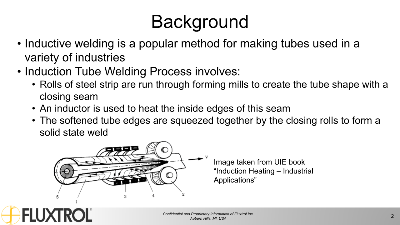
Inductive welding is a popular method for making tubes used in a variety of industries
Induction Tube Welding Process involves:
Rolls of steel strip are run through forming mills to create the tube shape with a closing seam
An inductor is used to heat the inside edges of this seam
The softened tube edges are squeezed together by the closing rolls to form a solid state weld
Figure 1: Image taken from UIE book “Induction Heating – Industrial Applications”
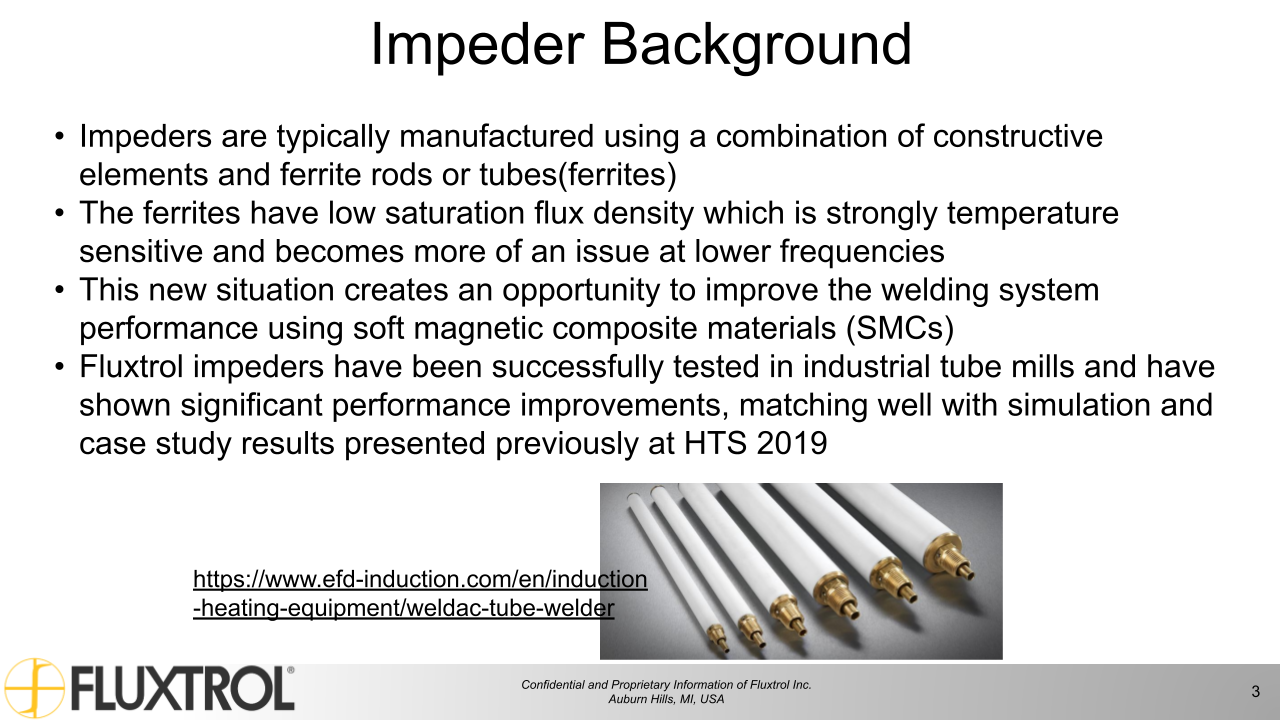
Impeder Background
Impeders are typically manufactured using a combination of constructive elements and ferrite rods or tubes(ferrites)
The ferrites have low saturation flux density which is strongly temperature sensitive and becomes more of an issue at lower frequencies
This new situation creates an opportunity to improve the welding system performance using soft magnetic composite materials (SMCs)
Fluxtrol impeders have been successfully tested in industrial tube mills and have shown significant performance improvements, matching well with simulation and case study results presented previously at HTS 2019
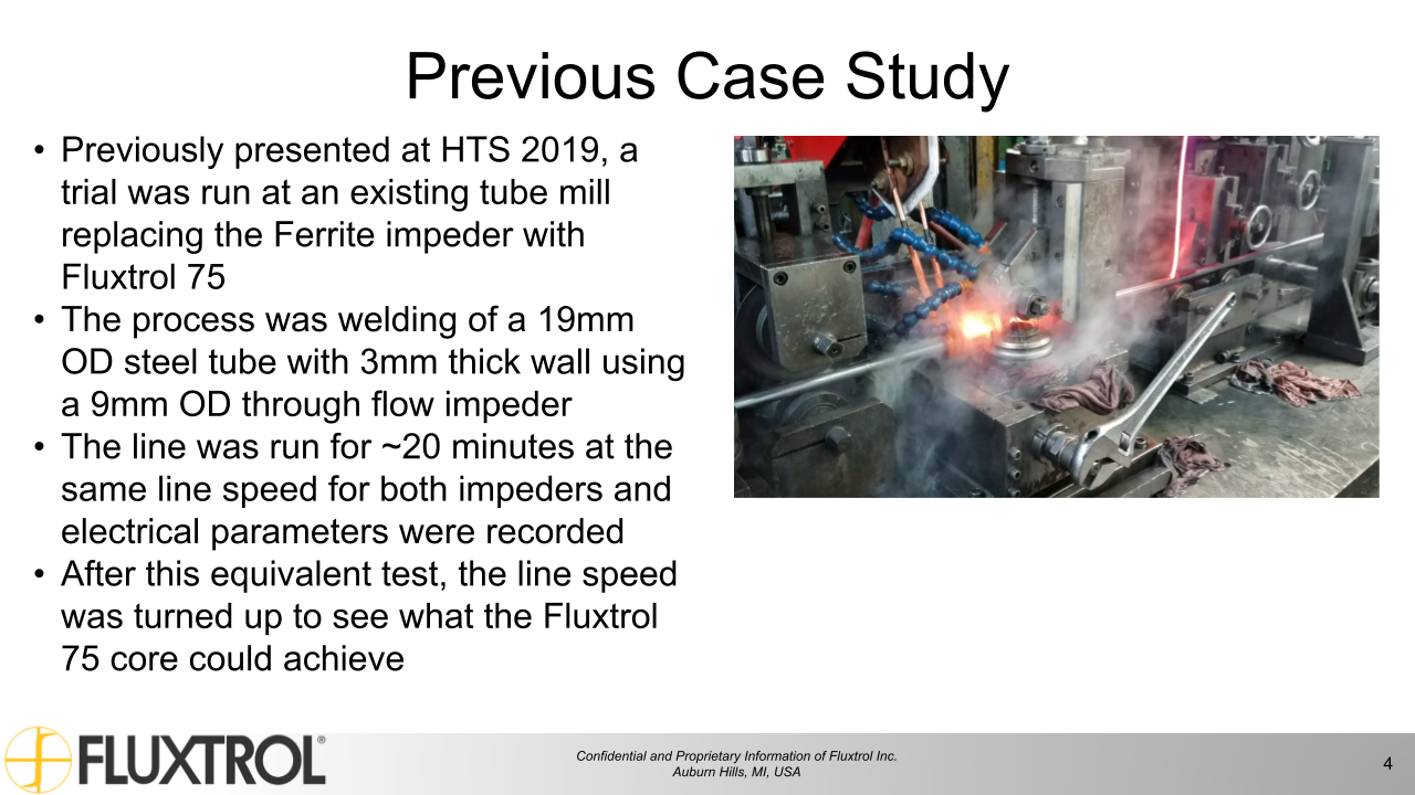
Previously presented at HTS 2019, a trial was run at an existing tube mill replacing the Ferrite impeder with Fluxtrol 75
The process was welding of a 19mm OD steel tube with 3mm thick wall using a 9mm OD through flow impeder
The line was run for ~20 minutes at the same line speed for both impeders and electrical parameters were recorded
After this equivalent test, the line speed was turned up to see what the Fluxtrol 75 core could achieve
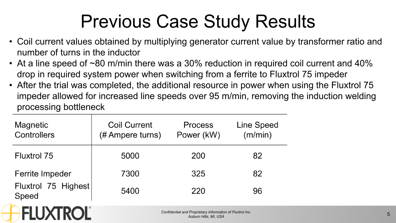
Previous Case Study Results
Coil current values obtained by multiplying generator current value by transformer ratio and number of turns in the inductor
At a line speed of ~80 m/min there was a 30% reduction in required coil current and 40% drop in required system power when switching from a ferrite to Fluxtrol 75 impeder
After the trial was completed, the additional resource in power when using the Fluxtrol 75 impeder allowed for increased line speeds over 95 m/min, removing the induction welding processing bottleneck
Magnetic Controllers
Coil Current (# Ampere turns)
Process Power (kW)
Line Speed (m/min)
Fluxtrol 75
5000
200
82
Ferrite Impeder
7300
325
82
Fluxtrol 75 Highest Speed
5400
220
96
Impeder Conditions
Based upon previous successful trials, we have done modelling to predict the effect of using Fluxtrol materials as the impeder core in tube welding systems
The models also show what conditions Fluxtrol materials will be exposed to
Due to higher saturation flux density, Fluxtrol materials have the potential to significantly improve the welding system parameters in applications where the ferrites are saturated
The concern is that due to higher losses of Fluxtrol materials compared to ferrites, can the impeders be cooled to survive these harsh conditions?
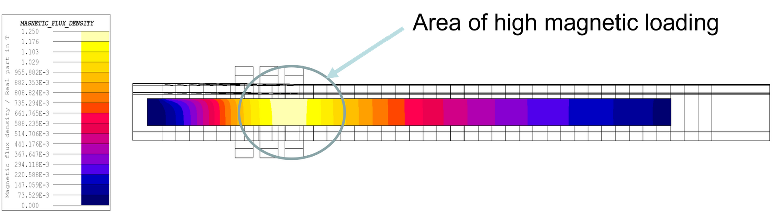
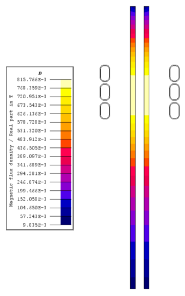
Below an example of a 3D model can be seen, showing magnetic flux density distribution in an impeder made of Fluxtrol A under extremely high loading
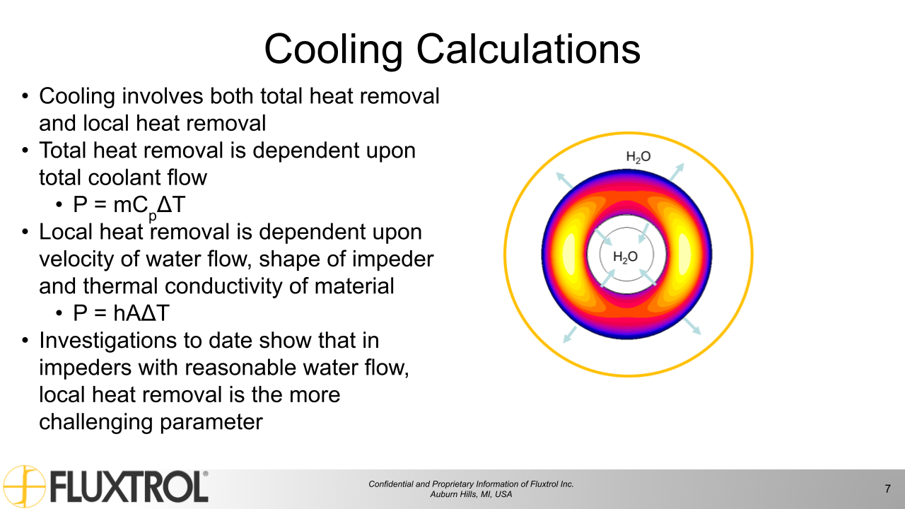
Cooling Calculations
Cooling involves both total heat removal and local heat removal
Total heat removal is dependent upon total coolant flow
P = mCpΔT
Local heat removal is dependent upon velocity of water flow, shape of impeder and thermal conductivity of material
P = hAΔT
Investigations to date show that in impeders with reasonable water flow, local heat removal is the more challenging parameter
Experimental Validation
While calculations based on the most current figures show that with proper design we can satisfactorily cool the Fluxtrol impeders in nearly all cases with water, we want practical data and the ability to test new impeders in-house before implementation at the customer site
These tests will allow us to understand if our calculations are correct, as well as provide guidelines for use in the field, including required water flowrates through the assembled impeder for a given process frequency and estimated magnetic loading
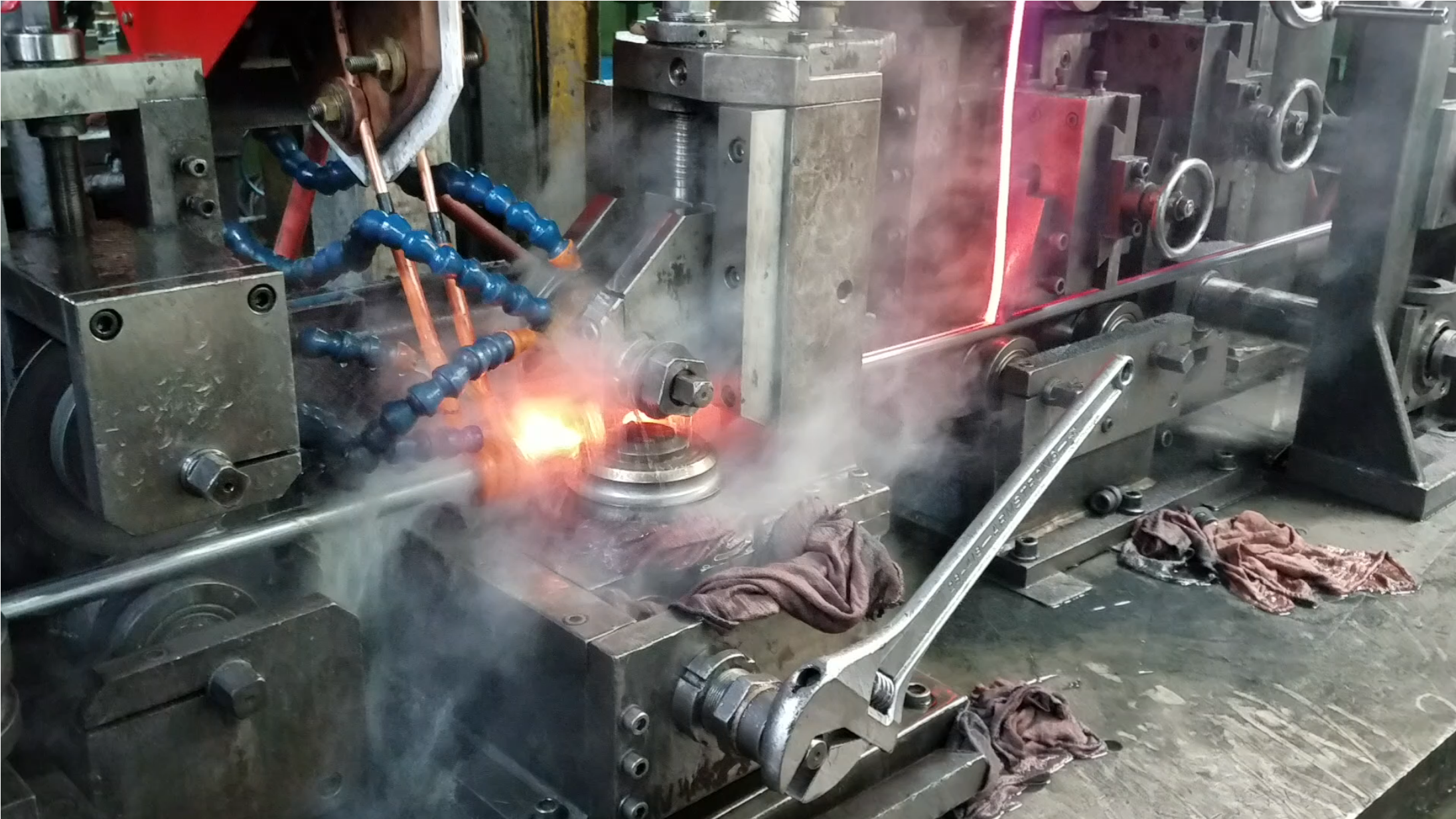
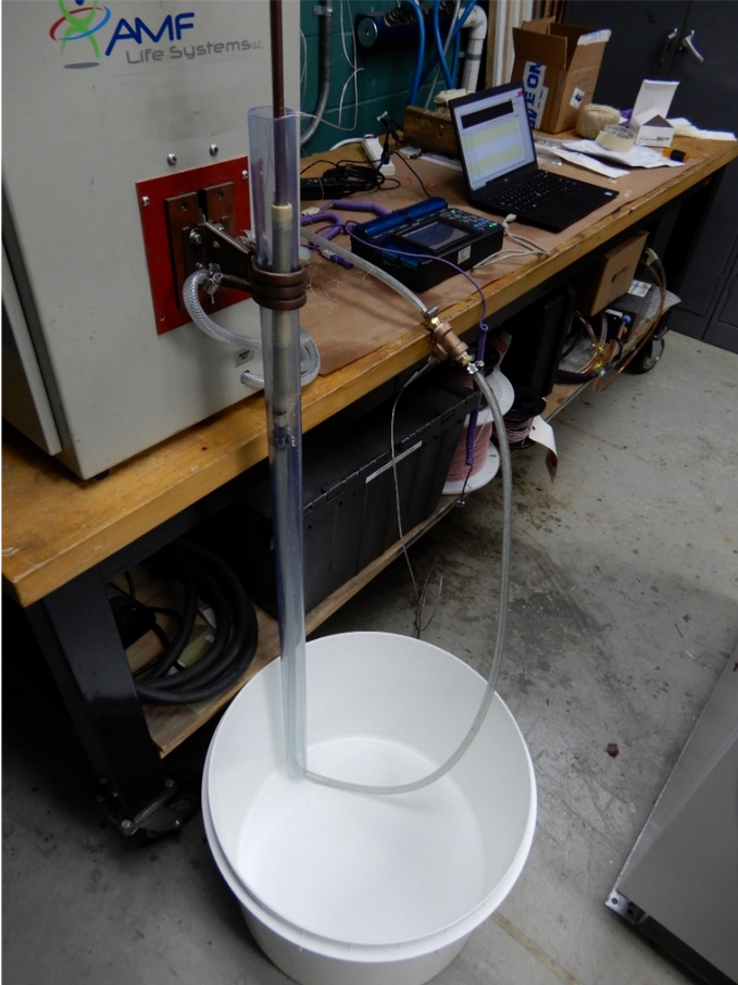
Experimental Setup
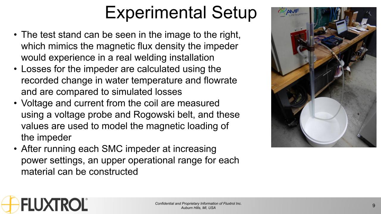
The test stand can be seen in the image to the right, which mimics the magnetic flux density the impeder would experience in a real welding installation
Losses for the impeder are calculated using the recorded change in water temperature and flowrate and are compared to simulated losses
Voltage and current from the coil are measured using a voltage probe and Rogowski belt, and these values are used to model the magnetic loading of the impeder
After running each SMC impeder at increasing power settings, an upper operational range for each material can be constructed
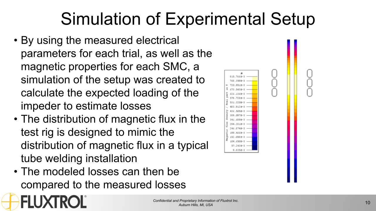
Simulation of Experimental Setup
By using the measured electrical parameters for each trial, as well as the magnetic properties for each SMC, a simulation of the setup was created to calculate the expected loading of the impeder to estimate losses
The distribution of magnetic flux in the test rig is designed to mimic the distribution of magnetic flux in a typical tube welding installation
The modeled losses can then be compared to the measured losses
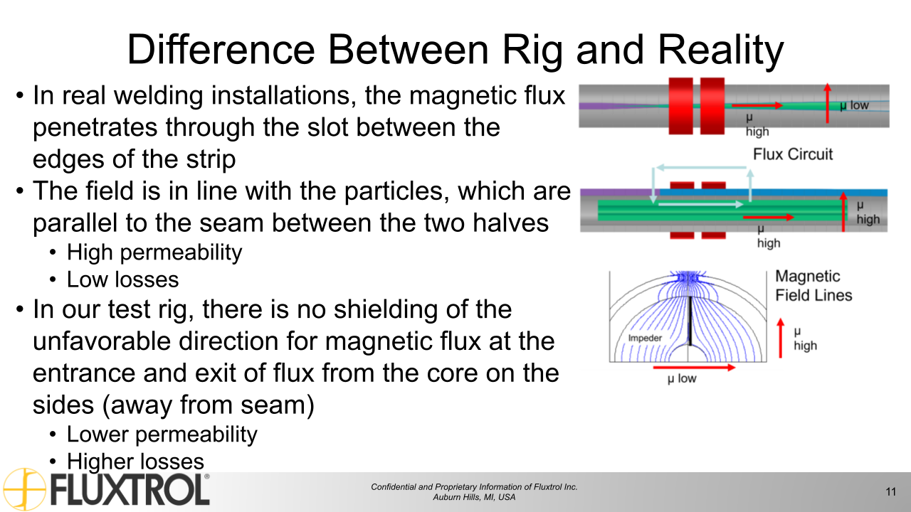
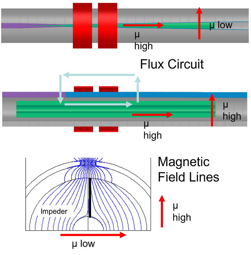
Difference Between Rig and Reality
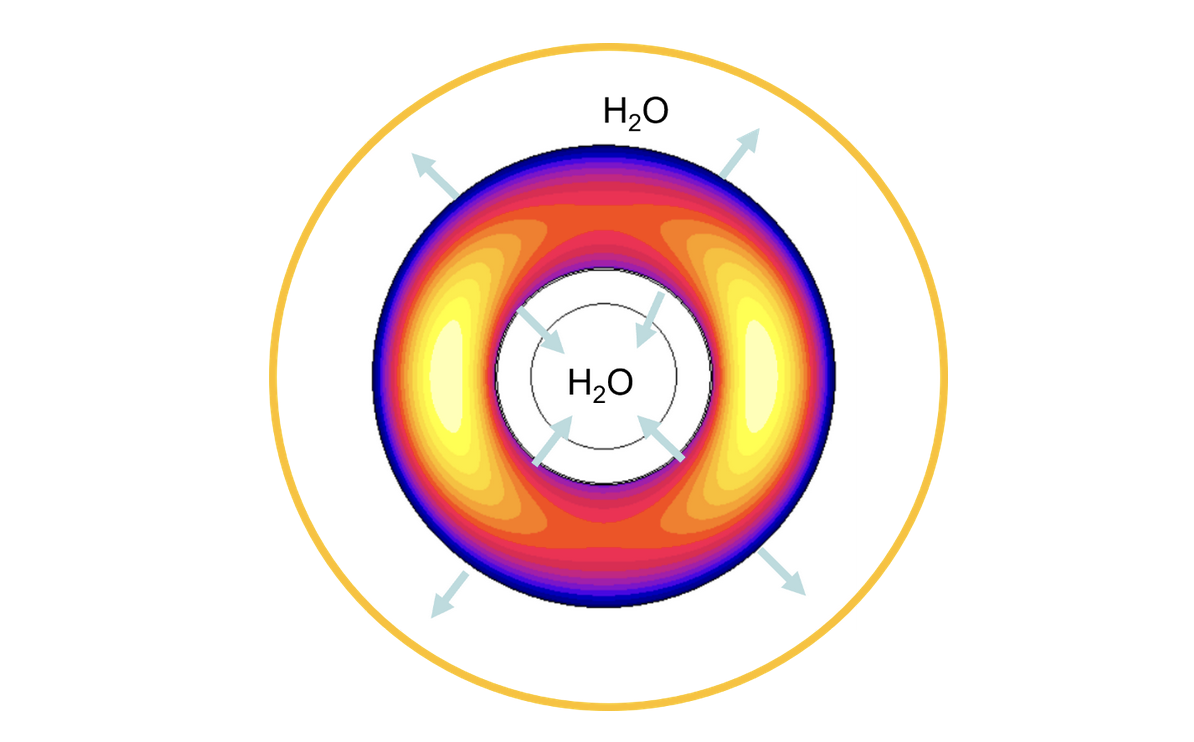
In real welding installations, the magnetic flux penetrates through the slot between the edges of the strip
The field is in line with the particles, which are parallel to the seam between the two halves
High permeability
Low losses
In our test rig, there is no shielding of the unfavorable direction for magnetic flux at the entrance and exit of flux from the core on the sides (away from seam)
Lower permeability
Higher losses
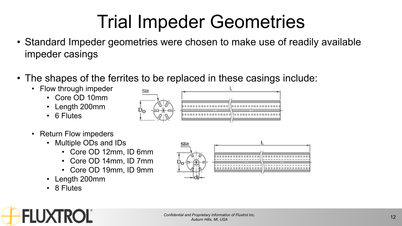
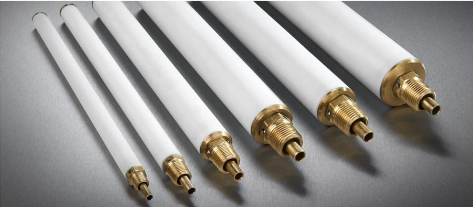
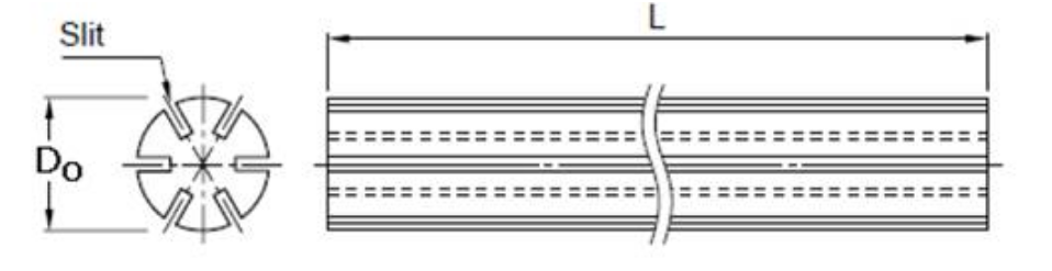
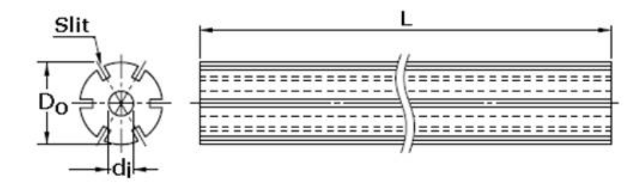
Trial Impeder Geometries
Standard Impeder geometries were chosen to make use of readily available impeder casings
The shapes of the ferrites to be replaced in these casings include:
Flow through impeder
Core OD 10mm
Length 200mm
6 Flutes
Return Flow impeders
Multiple ODs and IDs
Core OD 12mm, ID 6mm
Core OD 14mm, ID 7mm
Core OD 19mm, ID 9mm
Length 200mm
8 Flutes
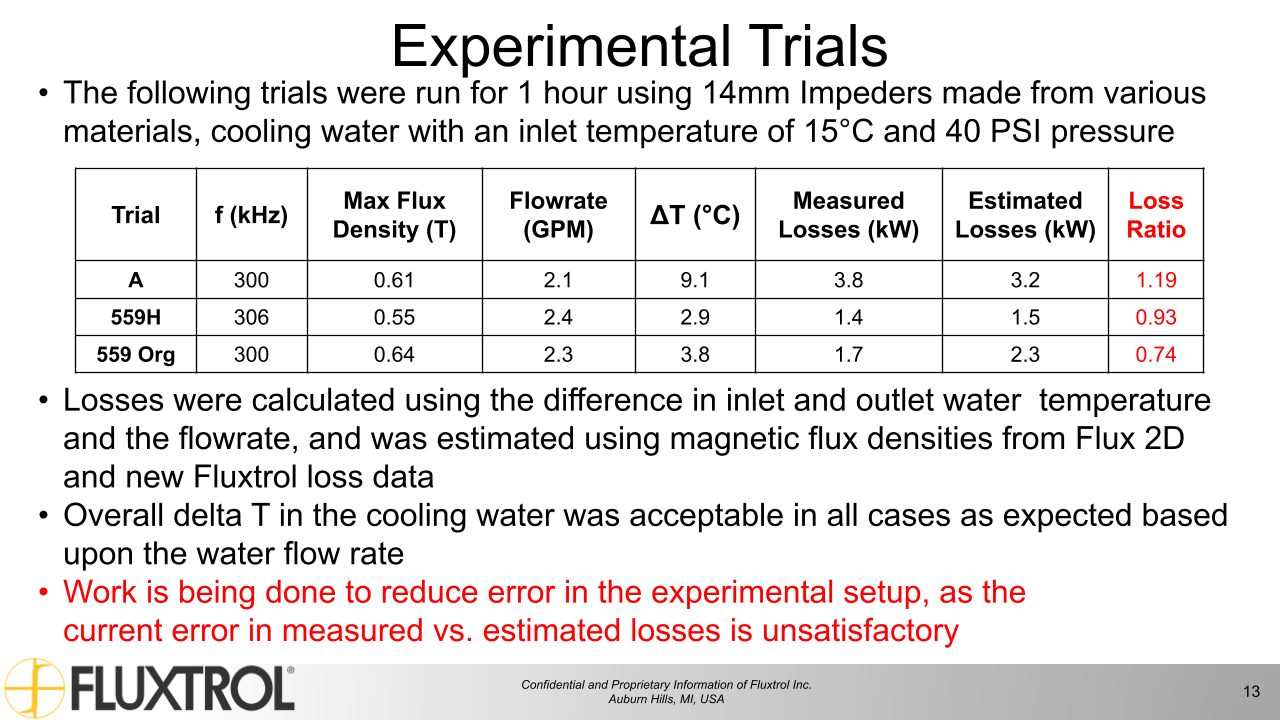
Experimental Trials
Trial
f (kHz)
Max Flux Density (T)
Flowrate (GPM)
ΔT (°C)
Measured Losses (kW)
Estimated Losses (kW)
Loss Ratio
A
300
0.61
2.1
9.1
3.8
3.2
1.19
559H
306
0.55
2.4
2.9
1.4
1.5
0.93
559 Org
300
0.64
2.3
3.8
1.7
2.3
0.74
The following trials were run for 1 hour using 14mm Impeders made from various materials, cooling water with an inlet temperature of 15°C and 40 PSI pressure
Losses were calculated using the difference in inlet and outlet water temperature and the flowrate, and was estimated using magnetic flux densities from Flux 2D and new Fluxtrol loss data
Overall delta T in the cooling water was acceptable in all cases as expected based upon the water flow rate
Work is being done to reduce error in the experimental setup, as the current error in measured vs. estimated losses is unsatisfactory
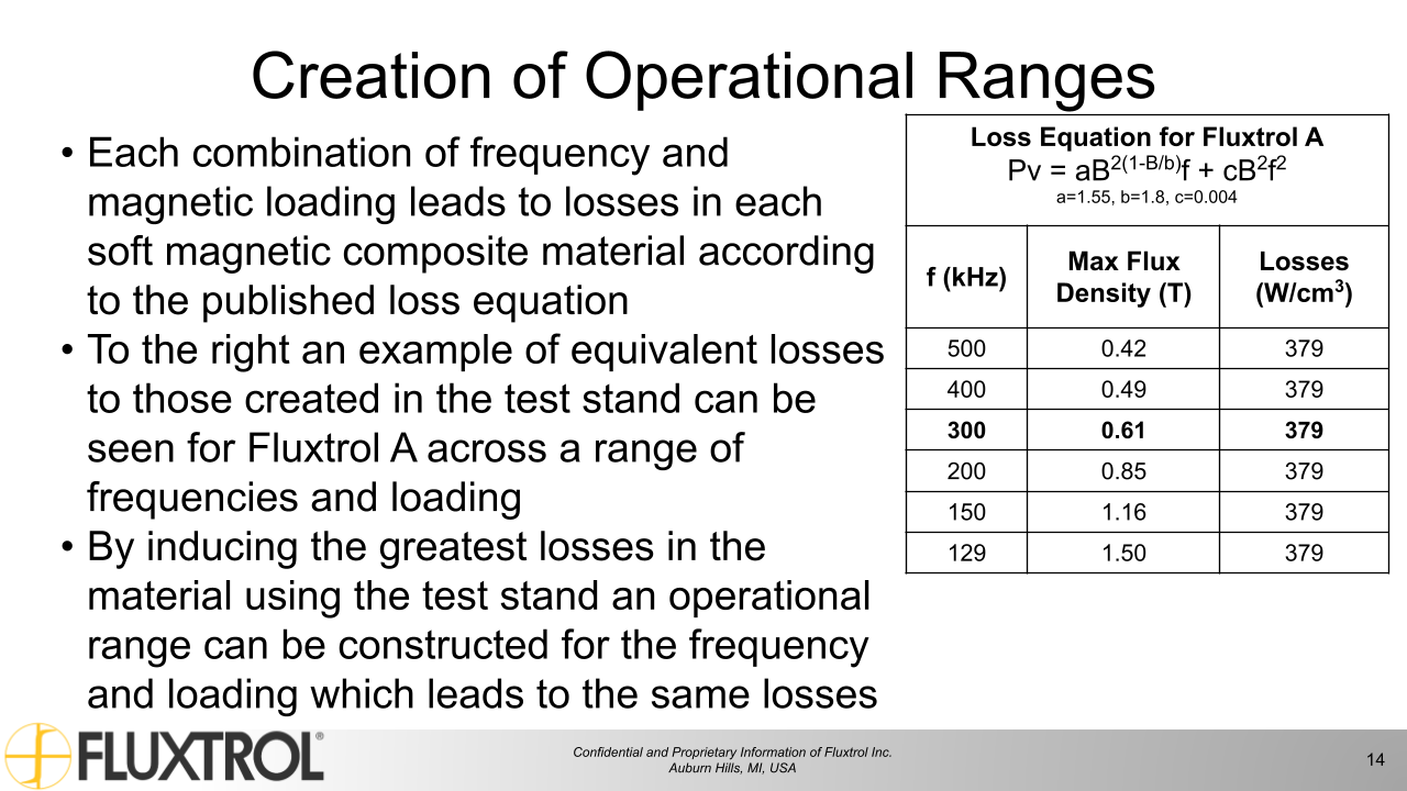
Creation of Operational Ranges
Loss Equation for Fluxtrol A
Pv = aB2(1-B/b)f + cB2f2
a=1.55, b=1.8, c=0.004
f (kHz)
Max Flux Density (T)
Losses (W/cm3)
500
0.42
379
400
0.49
379
300
0.61
379
200
0.85
379
150
1.16
379
129
1.50
379
Each combination of frequency and magnetic loading leads to losses in each soft magnetic composite material according to the published loss equation
To the right an example of equivalent losses to those created in the test stand can be seen for Fluxtrol A across a range of frequencies and loading
By inducing the greatest losses in the material using the test stand an operational range can be constructed for the frequency and loading which leads to the same losses
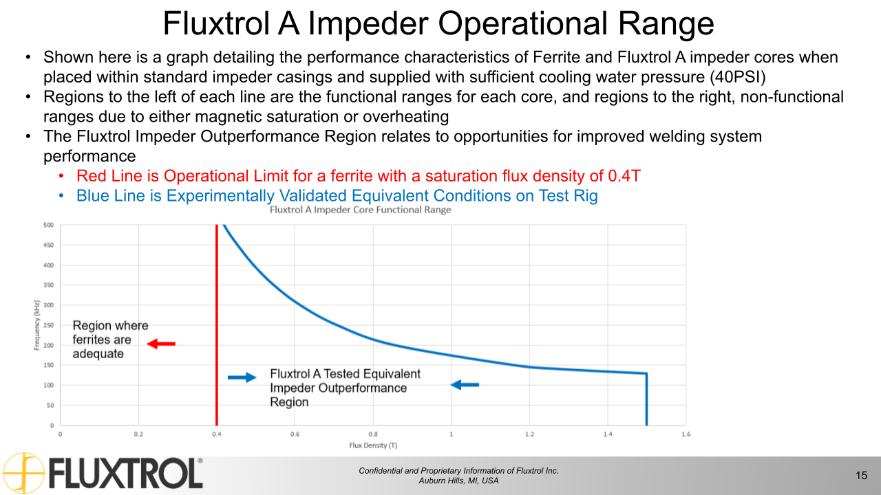
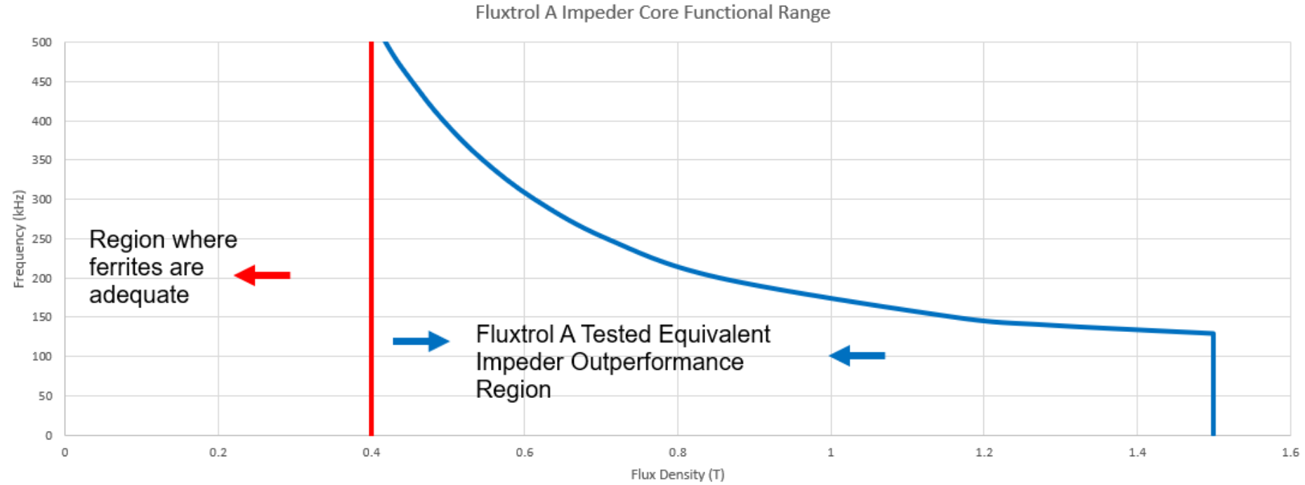
Fluxtrol A Impeder Operational Range
Shown here is a graph detailing the performance characteristics of Ferrite and Fluxtrol A impeder cores when placed within standard impeder casings and supplied with sufficient cooling water pressure (40PSI)
Regions to the left of each line are the functional ranges for each core, and regions to the right, non-functional ranges due to either magnetic saturation or overheating
The Fluxtrol Impeder Outperformance Region relates to opportunities for improved welding system performance
Red Line is Operational Limit for a ferrite with a saturation flux density of 0.4T
Blue Line is Experimentally Validated Equivalent Conditions on Test Rig
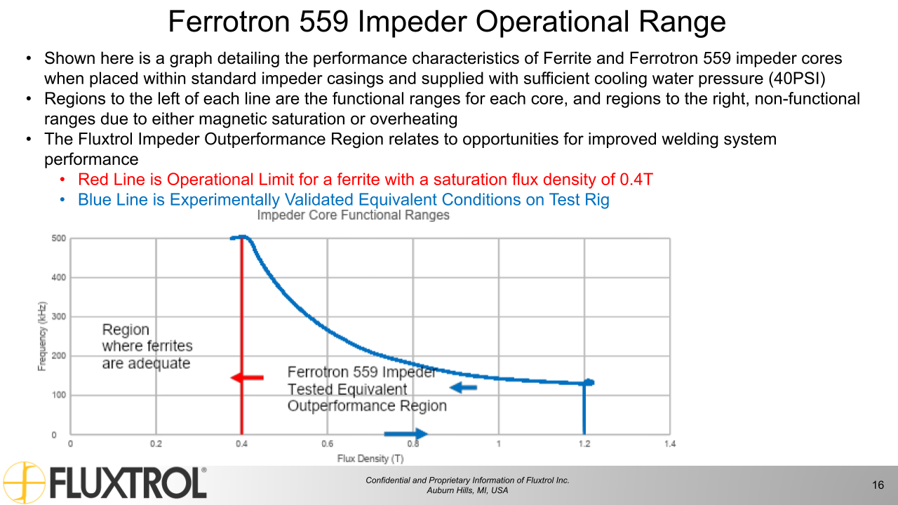
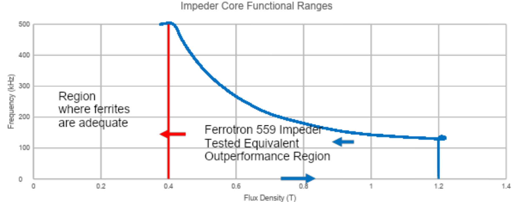
Ferrotron 559 Impeder Operational Range
Shown here is a graph detailing the performance characteristics of Ferrite and Ferrotron 559 impeder cores when placed within standard impeder casings and supplied with sufficient cooling water pressure (40PSI)
Regions to the left of each line are the functional ranges for each core, and regions to the right, non-functional ranges due to either magnetic saturation or overheating
The Fluxtrol Impeder Outperformance Region relates to opportunities for improved welding system performance
Red Line is Operational Limit for a ferrite with a saturation flux density of 0.4T
Blue Line is Experimentally Validated Equivalent Conditions on Test Rig
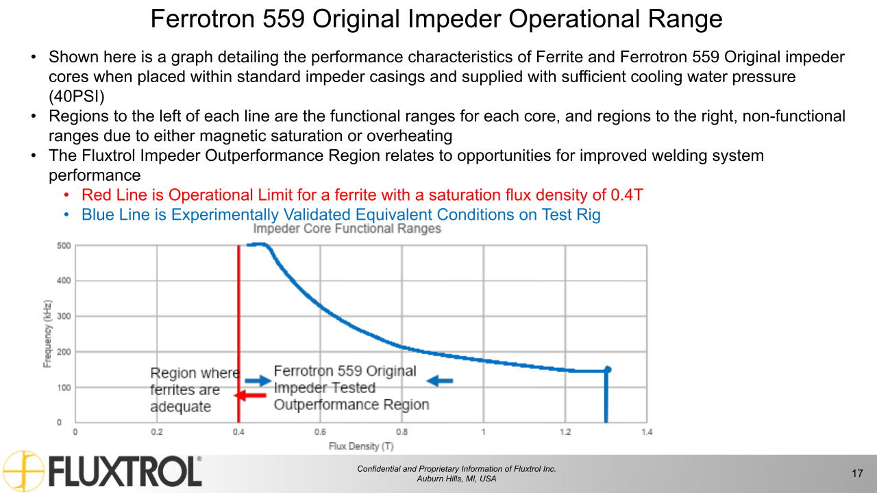
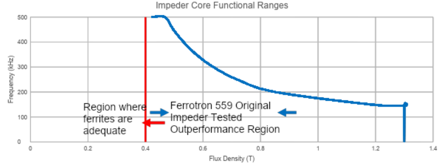
Ferrotron 559 Original Impeder Operational Range
Shown here is a graph detailing the performance characteristics of Ferrite and Ferrotron 559 Original impeder cores when placed within standard impeder casings and supplied with sufficient cooling water pressure (40PSI)
Regions to the left of each line are the functional ranges for each core, and regions to the right, non-functional ranges due to either magnetic saturation or overheating
The Fluxtrol Impeder Outperformance Region relates to opportunities for improved welding system performance
Red Line is Operational Limit for a ferrite with a saturation flux density of 0.4T
Blue Line is Experimentally Validated Equivalent Conditions on Test Rig
Theoretical vs. Experimentally Validated Operational Ranges
These previously shown operational ranges are based on the maximum loadings for each SMC impeder core that have been proven to survive on the test stand
The theoretical operation for each material is expected to cover a greater range of frequencies and magnetic loading
Work is planned to expand on the trials already preformed and expand the experimentally validated ranges
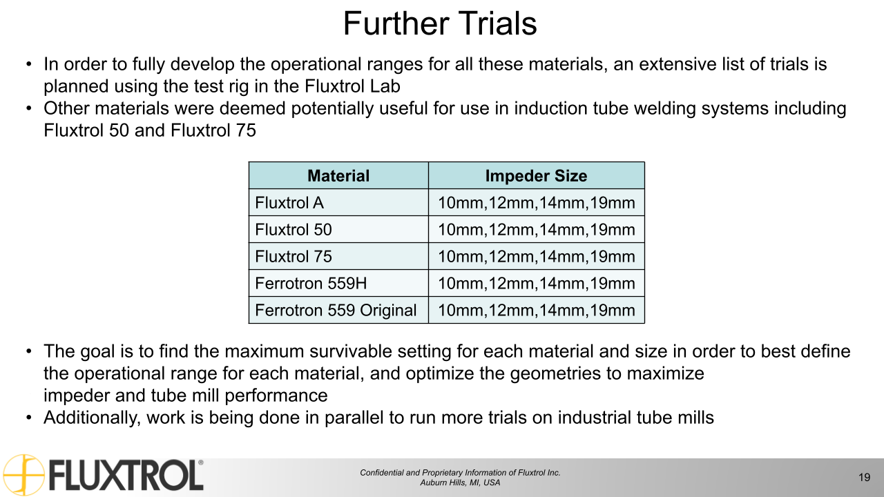
Further Trials
In order to fully develop the operational ranges for all these materials, an extensive list of trials is planned using the test rig in the Fluxtrol Lab
Other materials were deemed potentially useful for use in induction tube welding systems including Fluxtrol 50 and Fluxtrol 75
The goal is to find the maximum survivable setting for each material and size in order to best define the operational range for each material, and optimize the geometries to maximize impeder and tube mill performance
Additionally, work is being done in parallel to run more trials on industrial tube mills
Material
Impeder Size
Fluxtrol A
Impeder Size
Fluxtrol 50
10mm,12mm,14mm,19mm
Fluxtrol 75
10mm,12mm,14mm,19mm
Ferrotron 559H
10mm,12mm,14mm,19mm
Ferrotron 559 Original
10mm,12mm,14mm,19mm
Conclusions
An experimental test stand has been developed in the Fluxtrol laboratory for physical simulation of industrial tube welding conditions
Tests with 3 grades of SMC showed that the materials could survive at 300 kHz at flux densities exceeding the saturation flux density of ferrites commonly used for tube welding impeder cores
Potential for increased productivity and efficiency
Using published loss data, the equivalent loading was calculated at various frequencies showing the experimentally validated operational window for the SMC materials
For tube welding cases where the ferrite is saturated, there is room for improvement when switching to an SMC impeder provided there is proper cooling and system controls
If you have more questions, require service or just need general information, we are here to help.
Our knowledgeable Customer Service team is available during business hours to answer your questions in regard to Fluxtrol product, pricing, ordering and other information. If you have technical questions about induction heating, material properties, our engineering and educational services, please contact our experts by phone, e-mail or mail.
Fluxtrol Inc.
1388 Atlantic Boulevard,
Auburn Hills, MI 48326
Telephone: +1-800-224-5522
Outside USA: 1-248-393-2000
FAX: +1-248-393-0277