
Physical Simulation and Computational Modelling for Validation of Soft Magnetic Composite Impeder Performance
Information
Authors: Sean M. Muyskens, Robert C. Goldstein
Location/Venue: IMAT 2022 New Orleans, Louisiana
Overview
- Induction Tube Welding Process
- The problem with welding small tubes
- Impeder core material optimization
Background
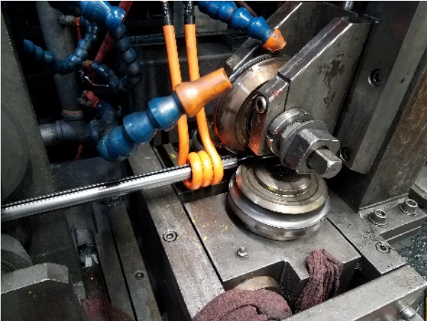
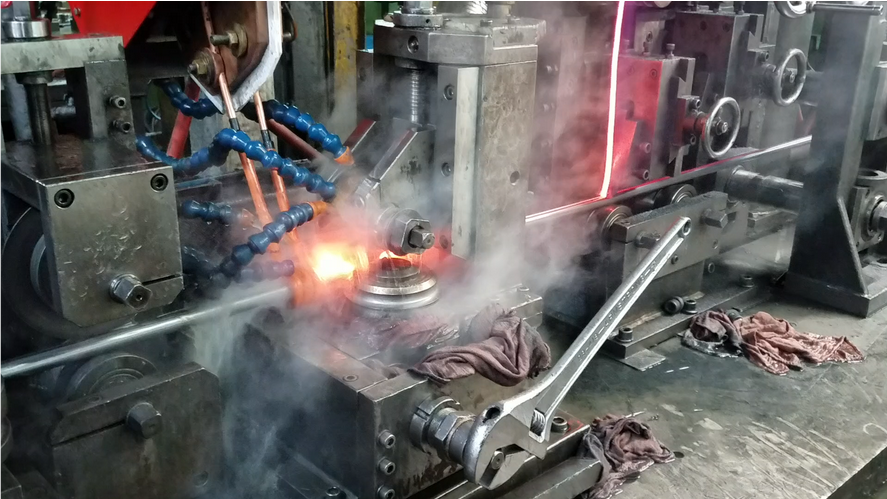
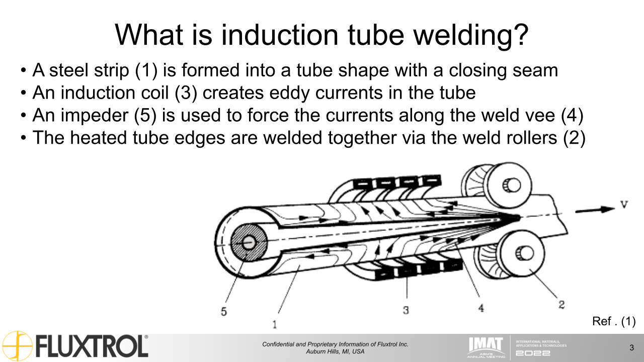
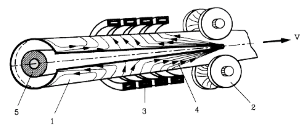
- A steel strip (1) is formed into a tube shape with a closing seam
- An induction coil (3) creates eddy currents in the tube
- An impeder (5) is used to force the currents along the weld vee (4)
- The heated tube edges are welded together via the weld rollers (2)
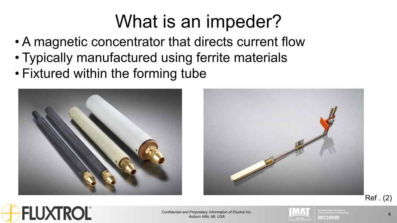
What is an impeder?
- A magnetic concentrator that directs current flow
- Typically manufactured using ferrite materials
- Fixtured within the forming tube
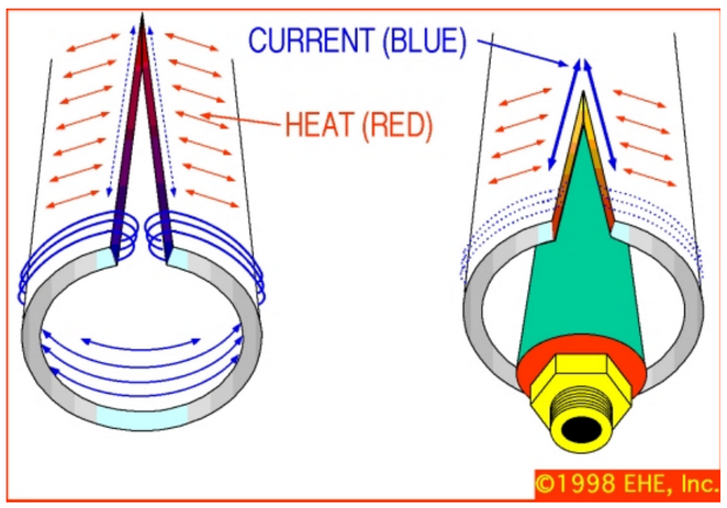
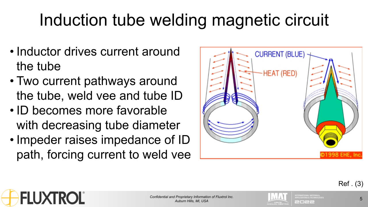
Induction tube welding magnetic circuit
- Inductor drives current around the tube
- Two current pathways around the tube, weld vee and tube ID
- ID becomes more favorable with decreasing tube diameter
- Impeder raises impedance of ID path, forcing current to weld vee
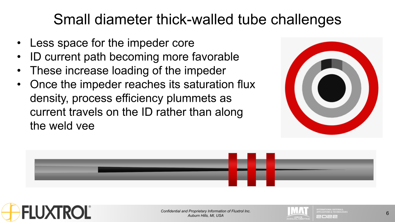
Small diameter thick-walled tube challenges
- Less space fore the impeder core
- ID current path becoming more favorable
- These increase loading of the impeder
- Once the impeder reaches its saturation flux density, process efficiency plummets as current travels on the ID rather than along the weld vee
Solutions
-
Add more power in cases where inefficiency is unavoidable
- Wasted heating away from weld vee
- Not feasible in many processes
-
Increase process efficiency by:
- Decreasing impeder loading
- Increasing impeder load capacity
Decreasing impeder loading
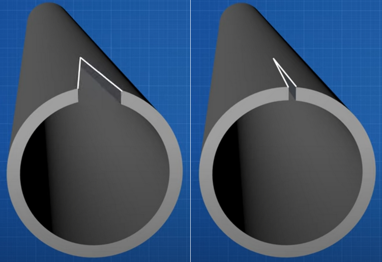
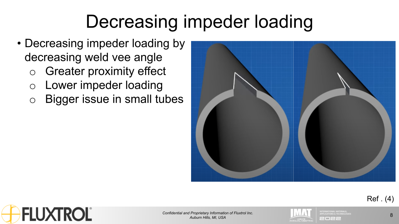
- Decreasing impeder loading by decreasing weld vee angle
- Greater proximity effect
- Lower impeder loading
- Bigger issue in small tubes
Increasing impeder load capacity
- Increasing impeder load capacity
- Use larger impeder
- Greater cooling of the core
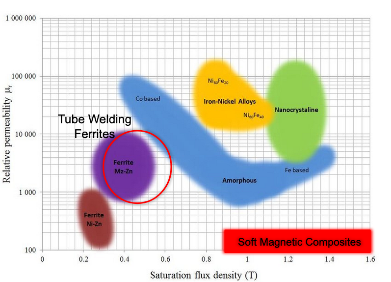
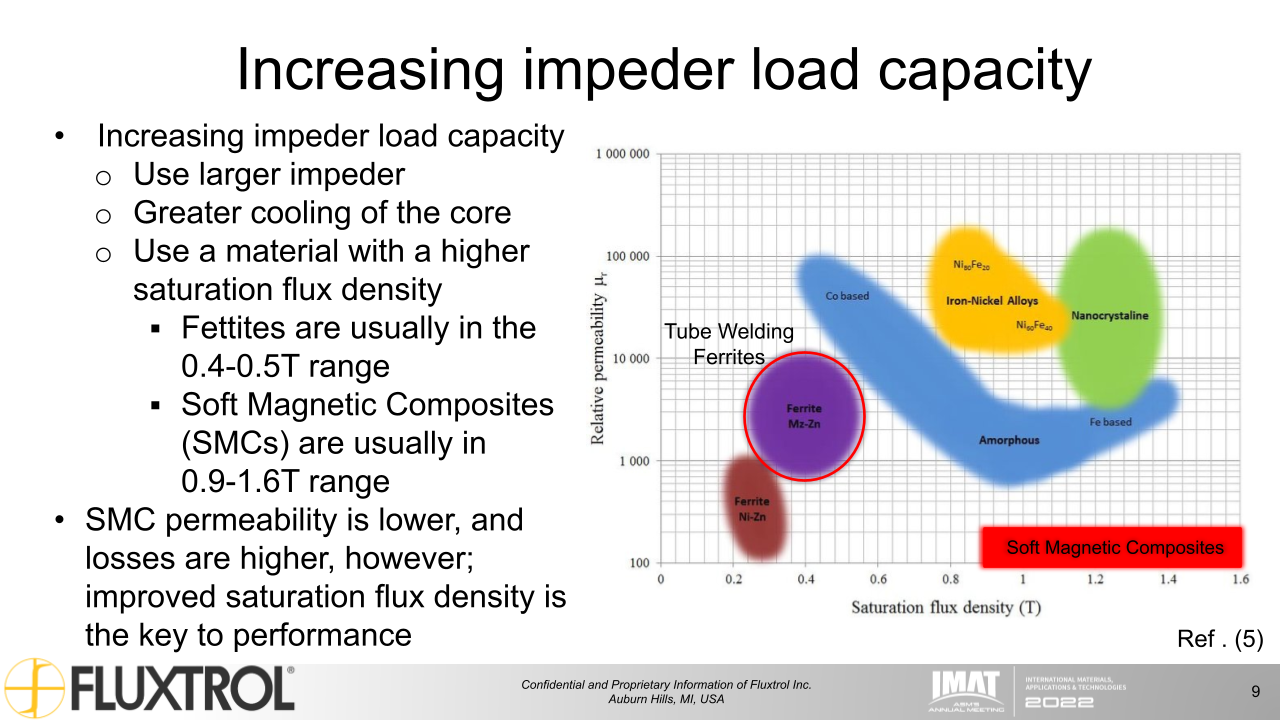
- Use a material with a higher saturation flux density
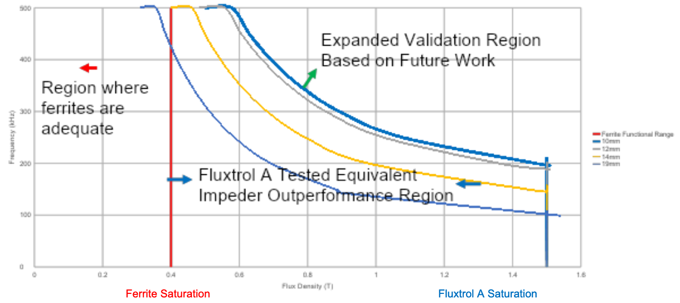
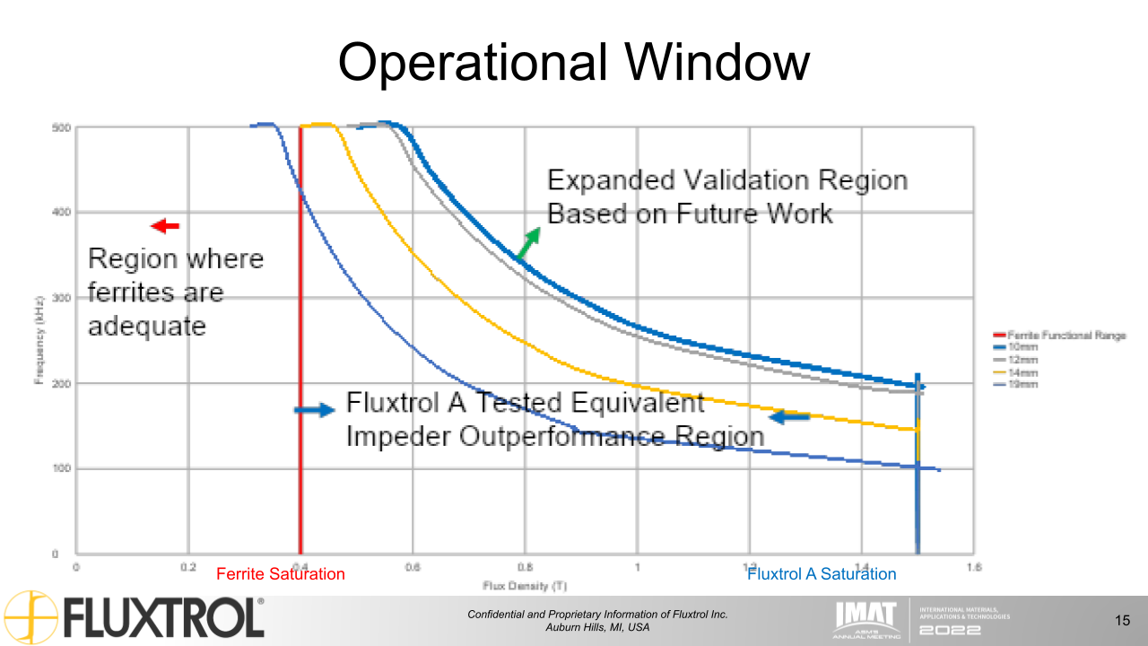
- Ferrites are usually in the 0.4-0.5T range
- Soft Magnetic Composites (SMCs) are usually in 0.9-1.6T range
- SMC permeability is lower, and losses are higher; however, improved saturation flux density is the key to performance
New technology adoption/transition
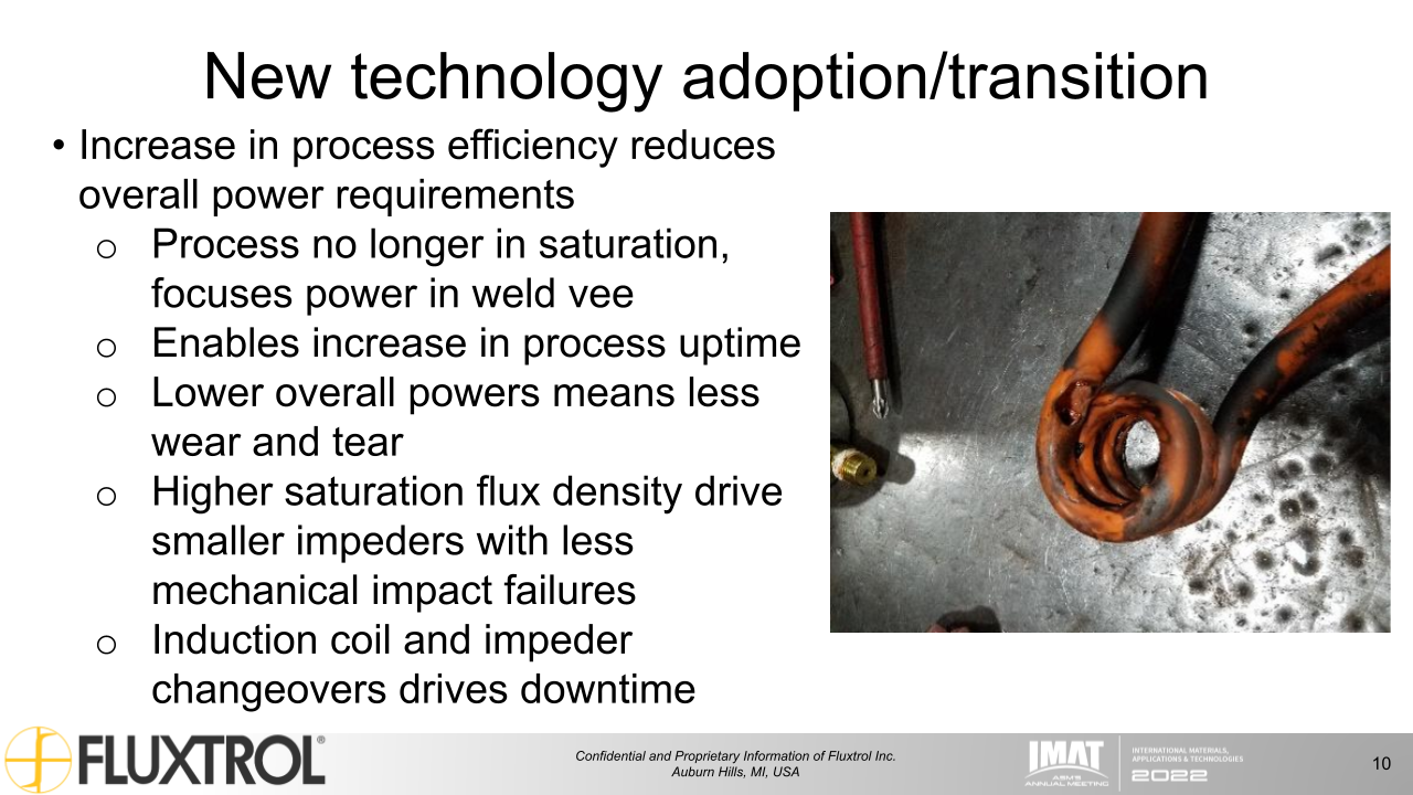
- Increase in process efficiency reduces overall power requirements
- Process no longer in saturation, focuses power in weld vee
- Enables increase in process uptime
- Lower overall powers means less wear and tear
- Higher saturation flux density drive smaller impeders with less mechanical impact failures
- Induction coil and impeder changeovers drive downtime
Case study energy savings
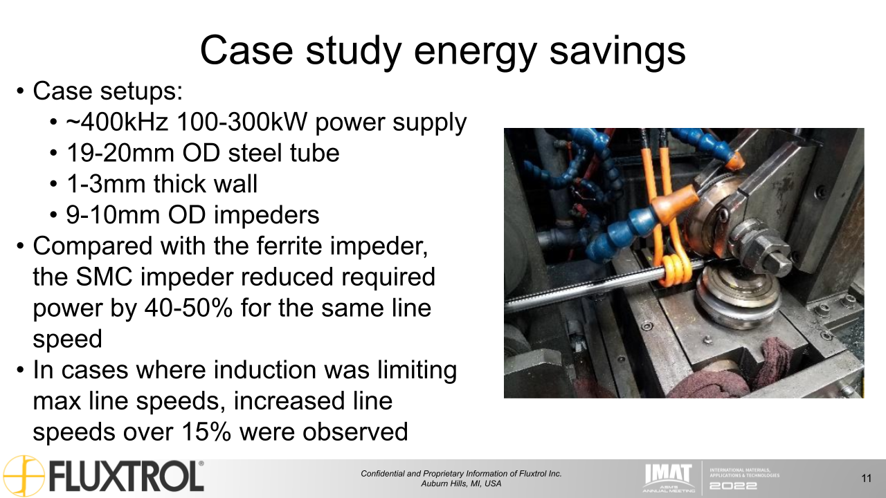
- Case setups:
- ~400kHz 100-300kW power supply
- 19-20mm OD steel tube
- 1-3mm thick wall
- 9-10mm OD impeders
- Compared with the ferrite impeder, the SMC impeder reduced required power by 40-50% for the same line speed
- In cases where induction was limiting max line speeds, increased line speeds over 15% were observed
Case study SMC impeder lifetime
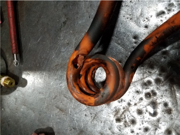
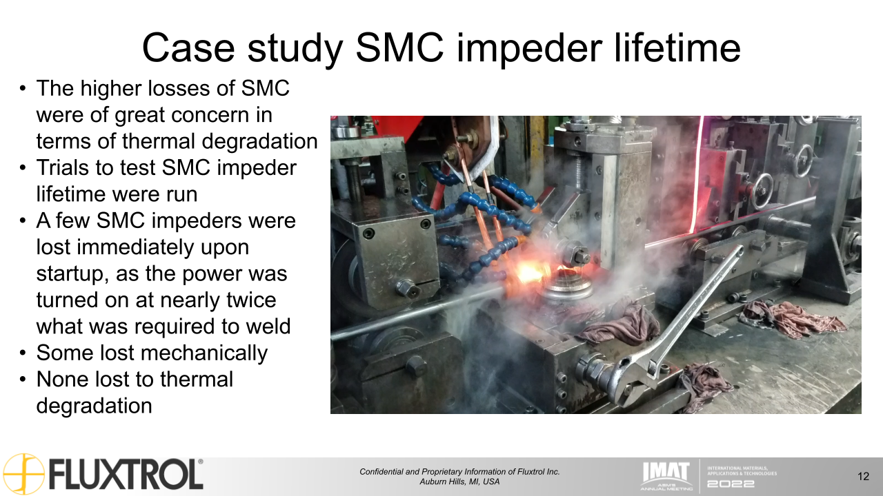
- The higher losses of SMC were of great concern in terms of thermal degradation
- Trials to test SMC impeder lifetime were run
- A few SMC impeders were lost immediately upon startup, as the power was turned on at nearly twice what was required to weld
- Some lost mechanically
- None lost to thermal degradation
Physical testing
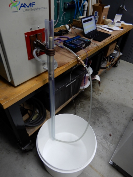
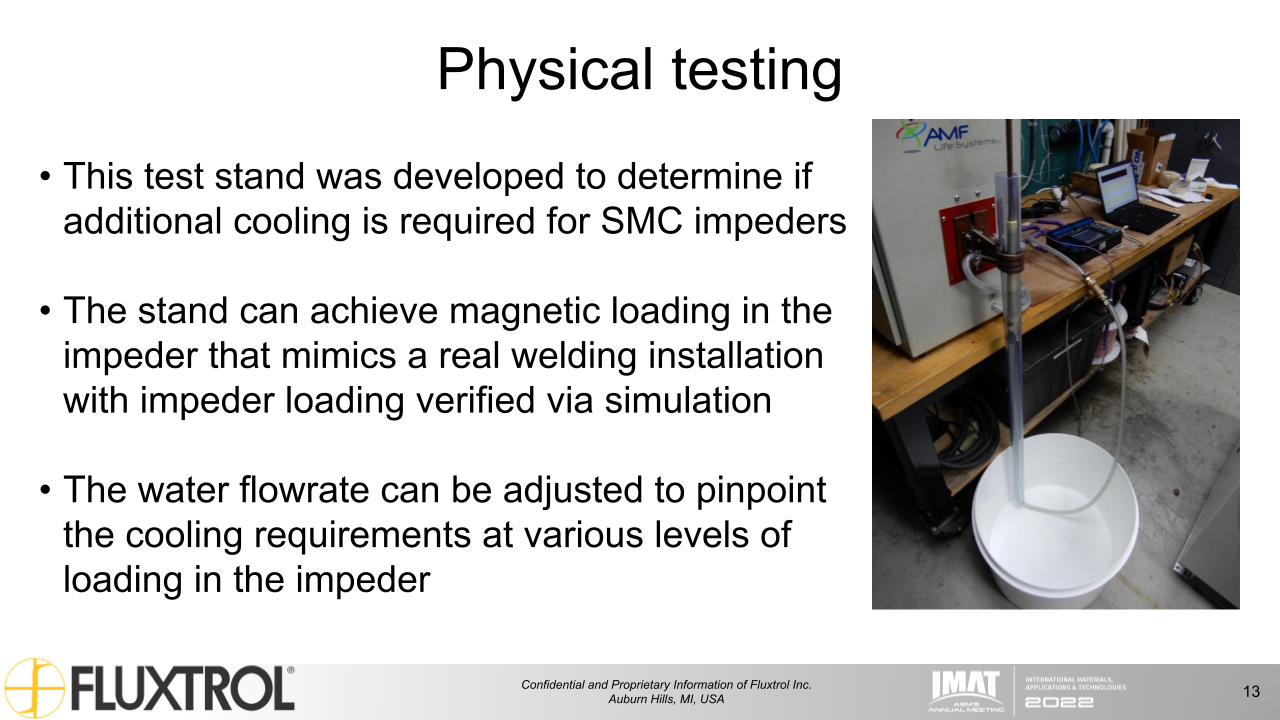
- This test stand was developed to determine if additional cooling is required for SMC impeders
- The stand can achieve magnetic loading in the impeder that mimics a real welding installation with impeder loading verified via simulation
- The water flowrate can be adjusted to pinpoint the cooling requirements at various levels of loading in the impeder
Physical testing result
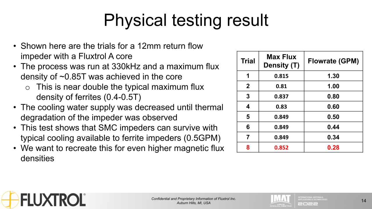
- Shown here are the trials for a 12mm return flow impeder with a Fluxtrol A core
- The process was run at 330kHz and a maximum flux density of ~0.85T was achieved in the core
- This is near double the typical maximum flux density of ferrites (0.4-0.5T)
- The cooling water supply was decreased until thermal degradation of the impeder was observed
- This test shows that SMC impeders can survive with typical cooling available to ferrite impeders (0.5GPM)
- We want to recreate this for even higher magnetic flux densities
Trial | Max Flux Density (T) | Flowrate (GPM) |
---|---|---|
1 | 0.815 | 1.30 |
2 | 0.81 | 1.00 |
3 | 0.837 | 0.80 |
4 | 0.83 | 0.60 |
5 | 0.849 | 0.50 |
6 | 0.849 | 0.44 |
7 | 0.849 | 0.34 |
8 | 0.852 | 0.28 |
Operational Window
Computational modelling
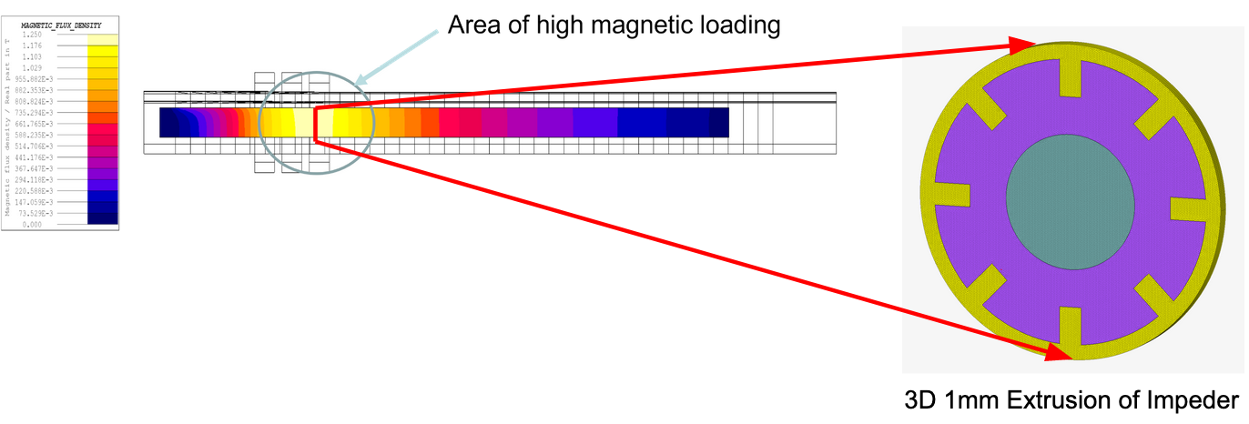
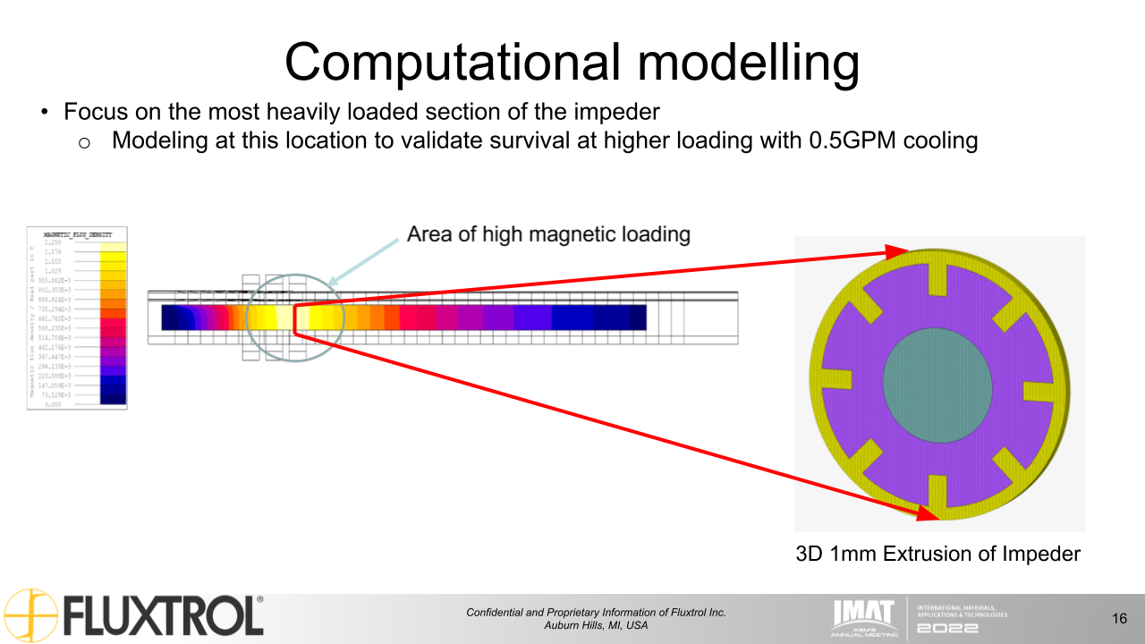
- Focus on the most heavily loaded section of the impeder
- Modeling at this location to validate survival at higher loading with 0.5GPM cooling
Computational modelling results
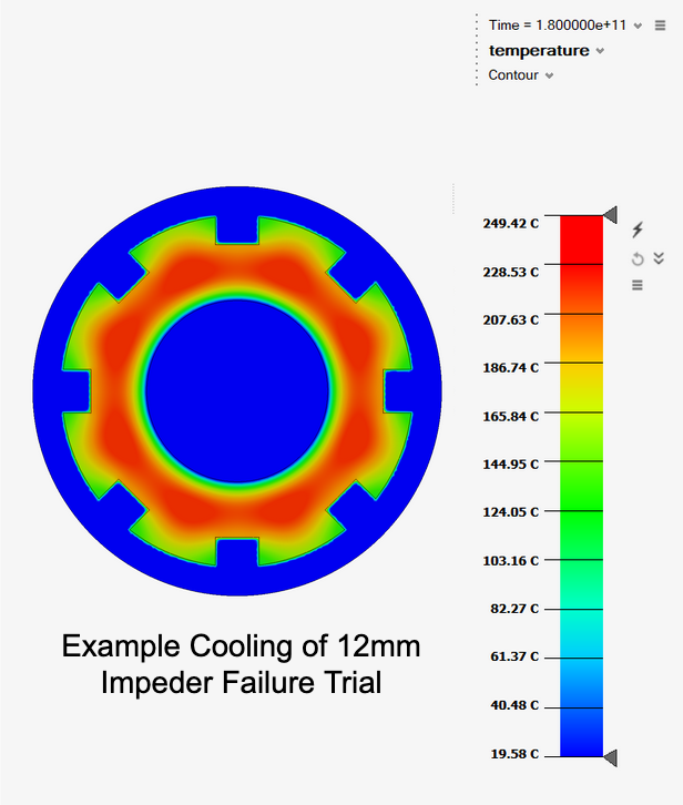
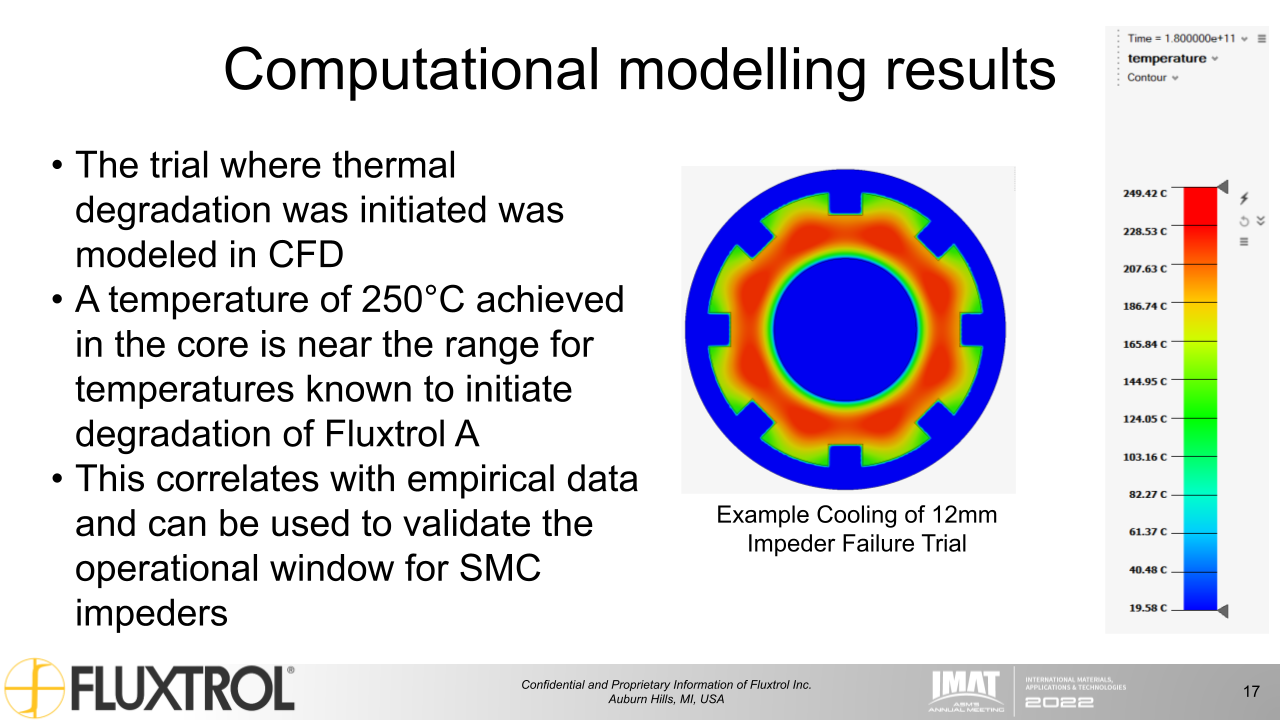
- The trial where thermal degradation was initiated was modeled in CFD
- A temperature of 250°C achieved in the core is near the range for temperatures known to initiate degradation of Fluxtrol A
- This correlates with empirical data and can be used to validate the operational window for SMC impeders
Conclusions
- Small tubes have posed an issue in induction tube welding
- Only small improvements can be made when the impeder is saturated
- A change in impeder material provides much greater improvements in saturation flux density
- Decreases required power
- Increases weld performance and line speed
- Decreases line downtime due to coil and impeder failures and replacement
- More testing needs to be performed on induction tube mills for validation of SMC impeders
Future work
- A new physical simulation setup is being constructed to validated survivability of SMCs at higher flux density
- CFD modelling to be used to expand SMC impeder operational window
- Test impeders are going to be evaluated on production weld lines for better empirical performance data
References
[1] Image taken from UIE book “Induction Heating – Industrial Applications”
[2] https://www.efd-induction.com/en/induction-heating-equipment/weldac-tube-welder
[3] Image taken from Tube & Pipe Technology “Optimizing Efficiency in HF Tube Welding Processes”
[4] Images taken from Thermatool Corp’s YouTube “Proximity Effect for High Frequency Welding of Tube and Pipe – Thermatool”
[5] https://www.researchgate.net/figure/Relative-permeability-vs-saturation-flux-density_fig1_321357089
If you have more questions, require service or just need general information, we are here to help.
Our knowledgeable Customer Service team is available during business hours to answer your questions in regard to Fluxtrol product, pricing, ordering and other information. If you have technical questions about induction heating, material properties, our engineering and educational services, please contact our experts by phone, e-mail or mail.
Fluxtrol Inc.
1388 Atlantic Boulevard,
Auburn Hills, MI 48326
Telephone: +1-800-224-5522
Outside USA: 1-248-393-2000
FAX: +1-248-393-0277