

Authors: Sean M. Muyskens, Robert C. Goldstein
Location/Venue: UIE 2021 Pilsen, Czech Republic
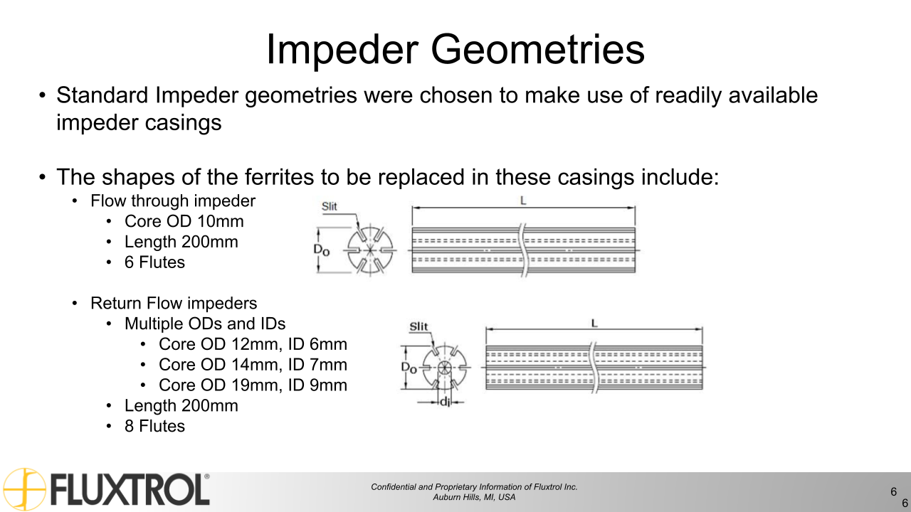
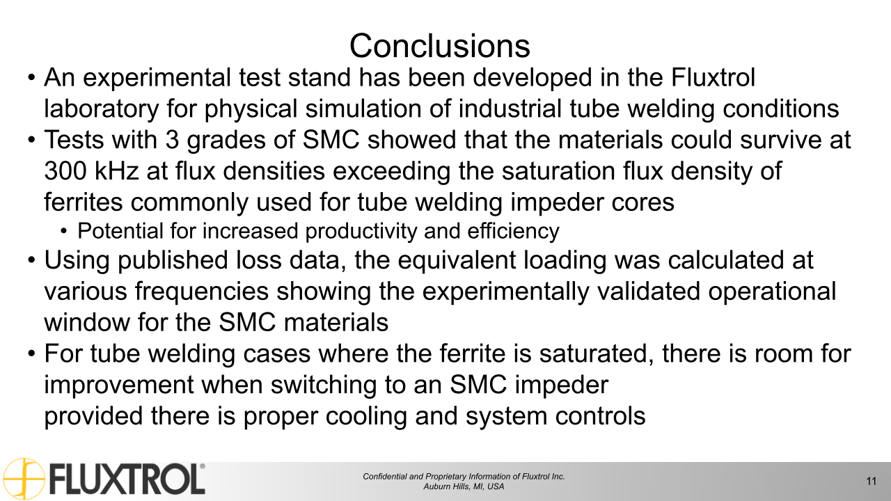
Induction tube welding is used for the continuous production of metallic tubes. These systems often utilize an internal magnetic flux controller (impeder) to improve process efficiency. Significant energy savings and increased productivity have been demonstrated both theoretically and practically when switching from the traditional ferrite impeder core, to one made of a soft magnetic composite (SMC) with high saturation flux density. In order to use SMCs in these systems it is important to balance the greater heat generated in these materials at higher fields with the cooling water available.
A test stand was devised for physical simulation of SMC impeder performance for use in induction tube welding systems. Tests were run to determine the loading and cooling conditions that an impeder core made of SMCs could survive. Additionally, loss estimates based on the rise in temperature from the cooling water were compared with published loss data for the SMCs used. The goal of these tests was to create a design envelope in which impeder cores made of SMCs could survive and validate their use in induction tube welding systems.
Inductive welding is a popular method for making tubes used in a variety of industries. Over the past 20-30 years, the industry has been transitioning from tube generators operating at 400 kHz, to solid state generators (either IGBT or MOSFET) which operate at frequencies from 50 kHz to 400 kHz. The availability of high power at lower frequencies has created the opportunity to successfully weld larger tubes with greater wall thicknesses for more demanding applications. At the same time, one of the key components of the system, the impeder, has not changed significantly, which is limiting the production rate or resulting quality of some types of tubing.
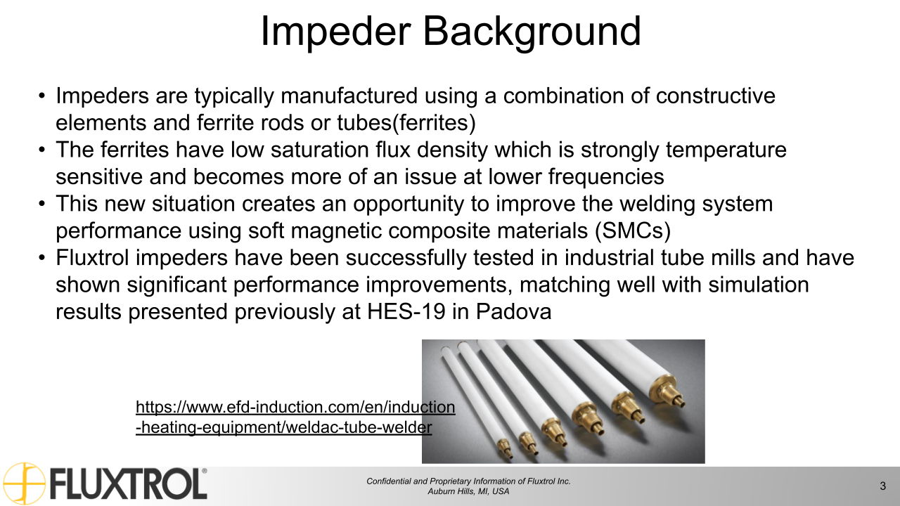
Impeders are typically manufactured using a combination of construction elements and ferrite rods or tubes (ferrites). Ferrites have a low saturation flux density which is strongly temperature sensitive, are limited in size availability and are very susceptible to mechanical and thermal shock. The saturation flux density becomes more and more of an issue for lower frequencies, where the desirable flux density for welding is higher. This new situation creates an opportunity to improve the welding system performance using soft magnetic composites (SMCs) [1-3].
With the greater saturation flux density associated with SMCs there is also an increased amount of heat generated that could lead to failure if not properly handled. A test stand was devised for physical simulation of SMC impeder performance for use in induction tube welding systems. Tests were run to determine the loading and cooling conditions that an impeder core made of SMCs could survive. The goal of these tests was to create a design envelope in which impeder cores made of SMCs could survive and validate their use in induction tube welding systems.
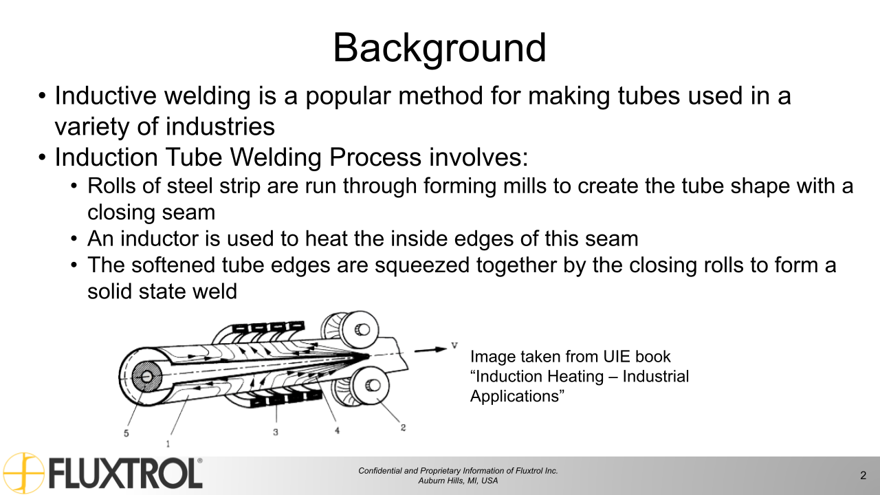
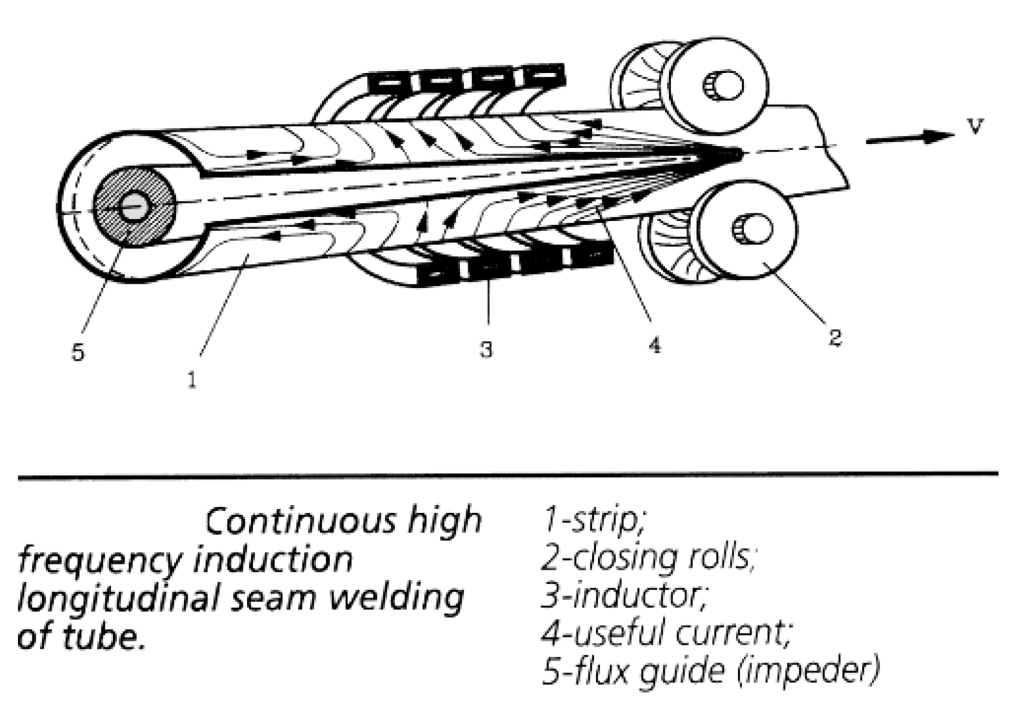
In induction tube welding, a steel sheet is formed into the profile of a tube by a series of rollers. As the profile is nearly formed, the edges of the strip form a vee shape, which is referred to as the weld vee. The point at which the vee terminates is often referred to as the apex or touching point. Just past the apex, a set of rollers apply pressure to create a solid-state bond. The size of the rollers depends upon the characteristics of the tube that is being welded. Near the last set of rollers, an induction coil is placed over the tube. Finally, an impeder is placed on the inside of the formed profile that extends from before the induction coil to near the apex. A basic geometry of the system is shown in Fig. 1 [4].
Currents are induced around the body of the strip under the induction coil. As the currents approach the edge of the vee, the currents have three main options for which direction to flow: on the edge towards the apex, on the edge towards the incoming material, or along the inside diameter of the tube. The currents flowing along the edge of the vee are what generates the heat necessary for the solid-state welding process [5].
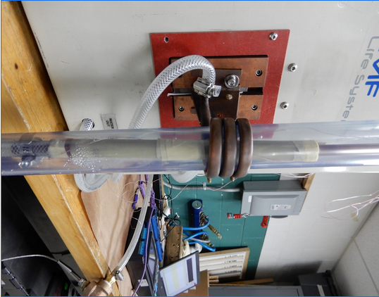
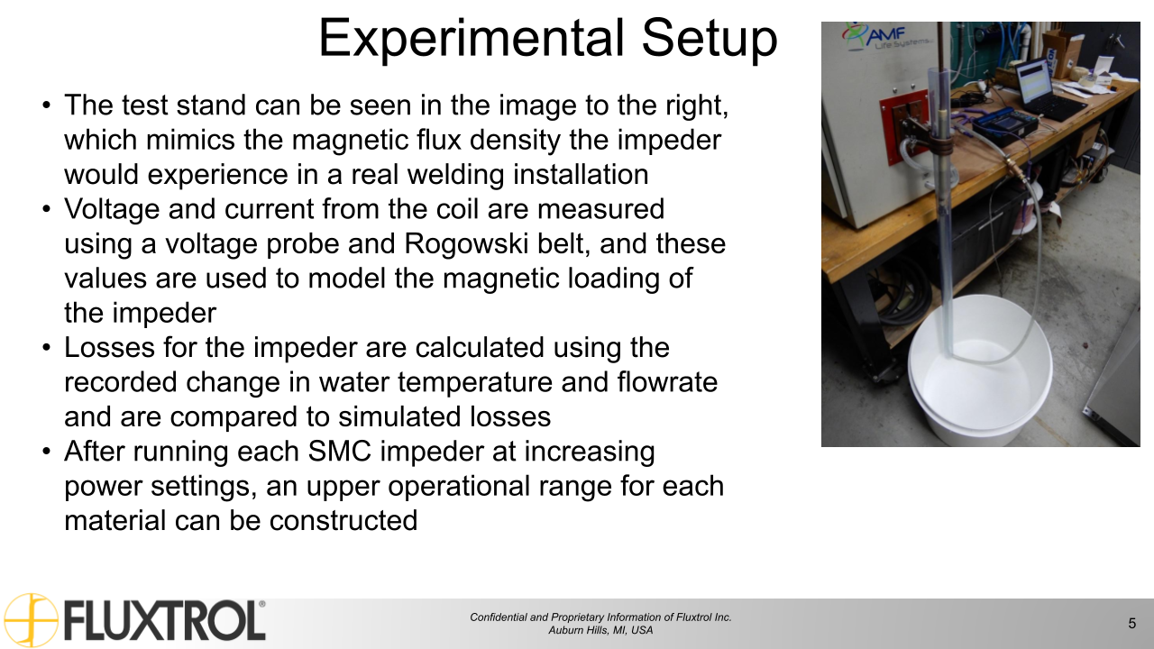
While it would be preferable to run tests on a full production line, a much more controllable test stand was constructed to simulate these conditions. The stand can be seen in Fig. 2. The major components are a 25kW PPST induction power supply, a three-turn inductor, impeder casings, and SMC impeder cores. There are also a variety of sensors (Rogowski belt, voltage probe, thermocouples) for measuring electrical parameters of the inductor and inlet and outlet temperature of the cooling water.
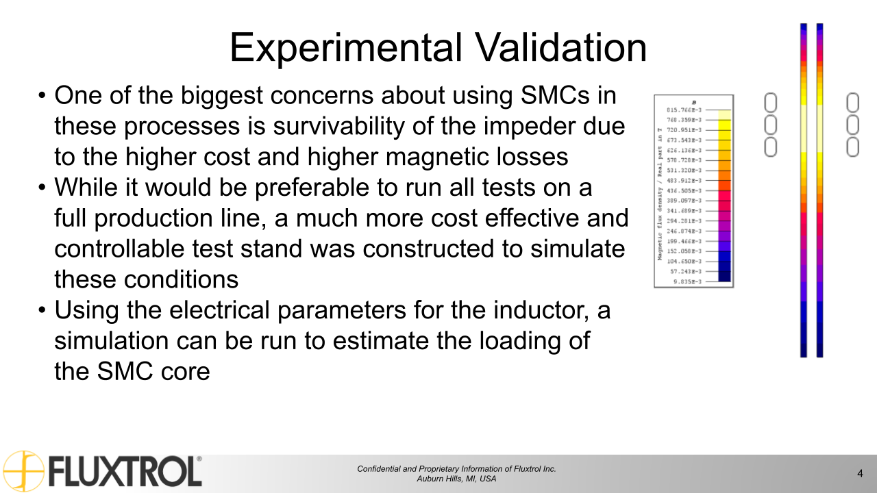
Using the electrical parameters for the inductor, a simulation can be run to estimate the loading of the SMC core. Loading and frequency allow for an estimation of losses that can be directly compared to measured loss based on the change in cooling water temperature at steady state. An additional thermal simulation will be run to estimate the temperature in the most heavily loaded portion of the core. This, along with inspection of the impeders between trials will be a good indication of survivability of the impeder in the real system.
To cut down on the number of independent variables, the water inlet will be kept at 40 PSI in each trial, and frequency and power will be adjusted to target the maximum sustainable levels of power density in the core. As the same power densities in the core could be achieved in the core at different power levels and frequencies from the power supply, simulation will be used to target required voltage across the inductor at the resonant frequency of each setup, and power will be adjusted accordingly.
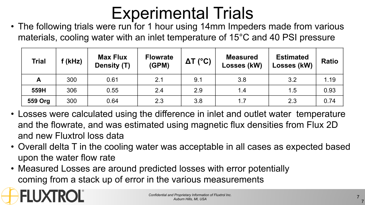
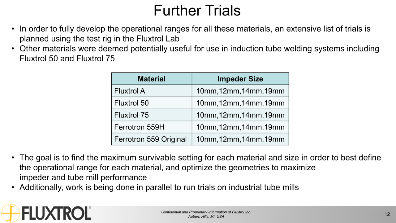
Table 1 show the planned trials where the major variables to be explored include impeder size and material. Each combination of impeder material and size will be run with three different cores at the maximum sustainable power to show repeatability. Each trial will be run for an hour to ensure there are no changes in electrical parameters that may point to degradation of the core.
| Trials | Impeder Materials | Impeder OD (mm) |
|---|---|---|
| 1-12 | Fluxtrol A | 10, 12, 14, 19 |
| 13-24 | Fluxtrol 75 | 10, 12, 14, 19 |
| 25-36 | Ferrotron 559H | 10, 12, 14, 19 |
| 37-48 | Ferrotron 559 Original | 10, 12, 14, 19 |
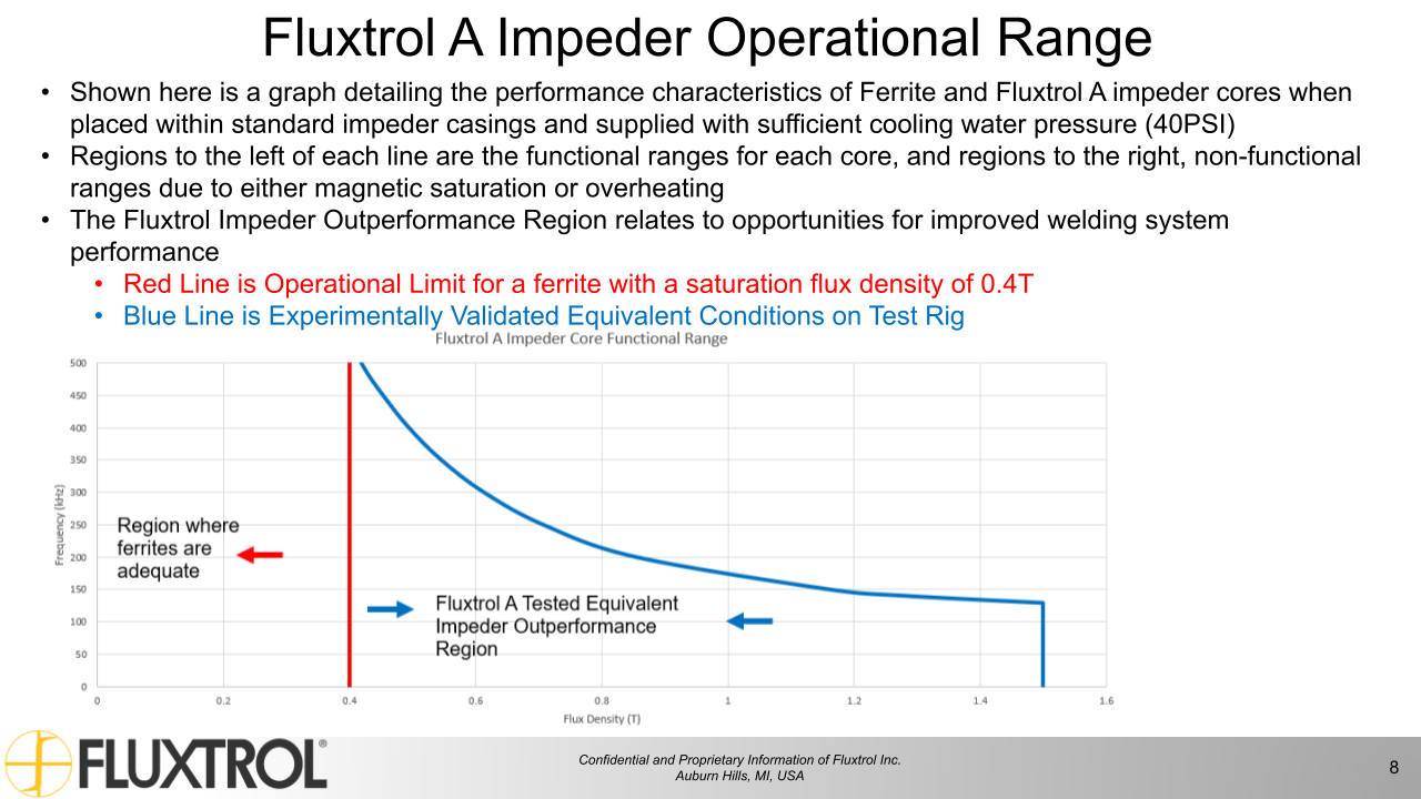
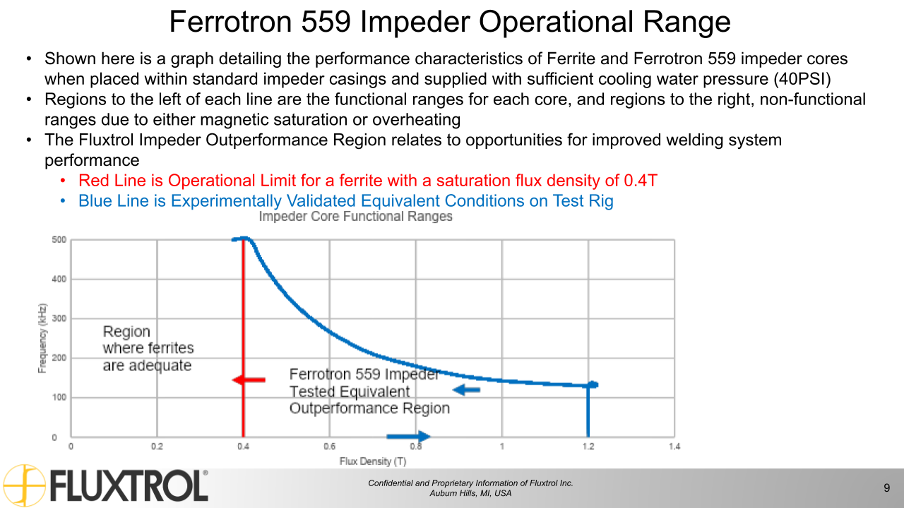
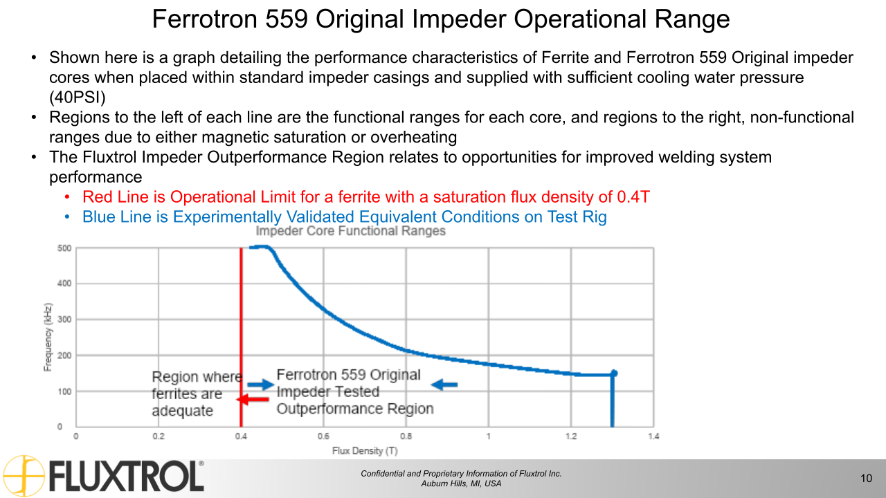
Fig. 3 below shows the operating envelope for Fluxtrol A based on trials run so far. The theoretical functional range was calculated using the simulated max flux density in the core based on the electrical parameters of the inductor recorded during each trial. The measured functional range was created based on measured calorimetric loss inversely calculated to a flux density that would correspond to the loss. As losses and power densities can vary based on frequency and field strength, results in Fig 3. demonstrate the maximum sustainable power density achieved in the core expanded over the full range of potential frequencies and magnetic loading one might expect in induction tube welding systems. This data was gathered using a single 14mm core made from Fluxtrol A and will be expanded with trials run in the other core sizes. Operating envelopes like that seen in Fig. 3 will be created for each SMC material detailed in Table I.
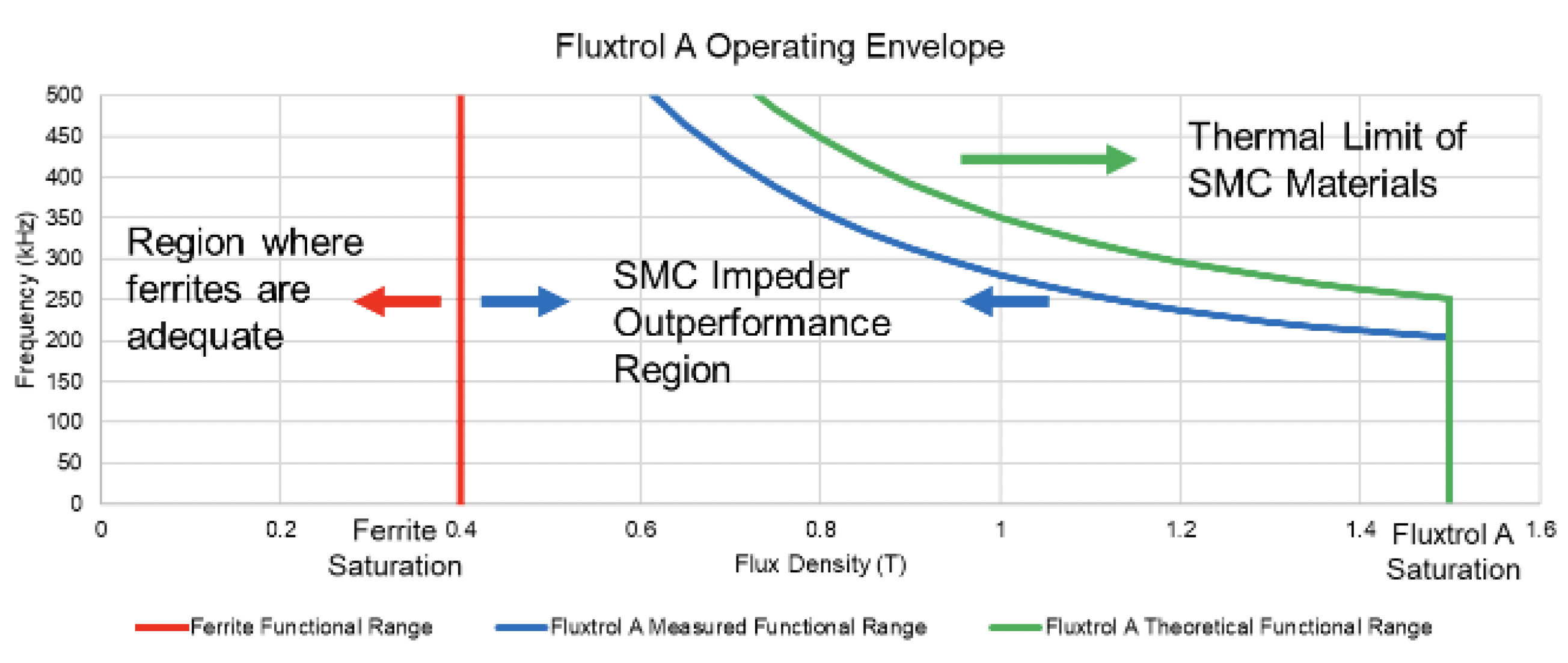
Initial trials using Fluxtrol A 14 mm impeder cores were run at combinations of flux densities and frequencies that significantly exceed the capabilities of ferrites. After 9 hours of use between all trials the core showed little damage caused by heating. The only sign of degradation being a single point where the protective coating had chipped leading to very minor corrosion due to water exposure. Given that there was little to no damage to the cores, the conclusion of these trials is that SMCs are viable for use in induction tube welding systems given they are supplied with sufficient cooling, in this case an inlet at 40PSI. When looking at tube welding cases where the ferrite is saturated, see the ferrite functional range in Fig 3., there is room for improvement when switching to an SMC impeder.
[1] Goldstein, R.C. (2014). “Magnetic flux controllers in induction heating and melting.” ASM Handbook Volume 4C, 633-645.J. Clerk Maxwell, A Treatise on Electricity and Magnetism, 3rd ed., vol. 2. Oxford: Clarendon, 1892, pp.68–73.
[2] Nemkov, V. (2008). “Magnetic flux guide for continuous high frequency welding of closed profiles.” US Patent Application, US20080308550A1.
[3] Muyskens, S., Eddir, T. and Goldstein, R. (2019), "Improving induction tube welding system performance using soft magnetic composites", COMPEL - The international journal for computation and mathematics in electrical and electronic engineering , Vol. ahead-of-print No. ahead-of-print. https://doi.org/10.1108/COMPEL-06-2019-0232
[4] Lupi, S., et. al. (1992). Induction Heating Industrial Applications. UIE, “Induction heating” working group, 73
[5] Scott, P.F. (2014). Key Parameters of High Frequency Welding. A Thermatool Corp. Publication, https://thermatool.com/resources/ technical-papers/
Our knowledgeable Customer Service team is available during business hours to answer your questions in regard to Fluxtrol product, pricing, ordering and other information. If you have technical questions about induction heating, material properties, our engineering and educational services, please contact our experts by phone, e-mail or mail.
Fluxtrol Inc.
1388 Atlantic Boulevard,
Auburn Hills, MI 48326
Telephone: +1-800-224-5522
Outside USA: 1-248-393-2000
FAX: +1-248-393-0277