Information
Authors: Tareq Eddir (Fluxtrol Inc.), Robert C. Goldstein (Fluxtrol Inc.), Robert Haun (Anspanner LLC)
Location/Venue: IMAT 2021 St. Louis, Missouri
Outline
- Billet Casters Background
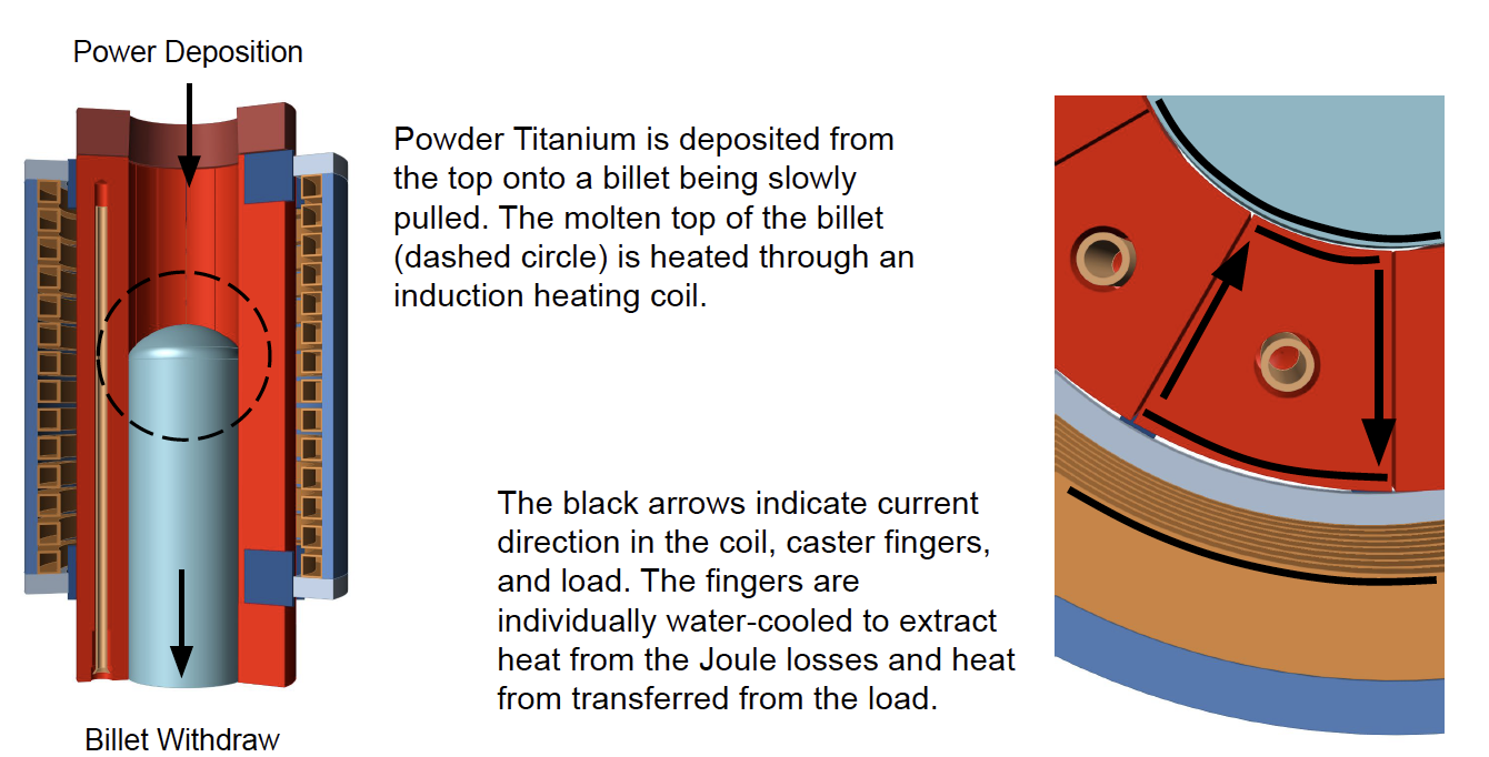
- Process Description
- Geometry Description
- Simulation Description
- Power Density Results
- Temperature Results
- Grain Structure Examples
- Conclusions and Future Work
Background
- Additive manufacturing of Ti alloys requires specific powder size ranges
- Size range of powder production methods is larger than AM techniques can use
- Oversize or undersize powder fractions are not usable in most applications of components produced by hot isostatic pressing
- Most oversize or undersize powder is sold as an alloy addition for steel making
- To recycle oversize or undersize powder for reuse, the powder must be consolidated for EiGA or other drip melting applications
- Those companies with cold wall induction crucible melting and bottom or tilt pouring equipment can easily remelt out of specification powder
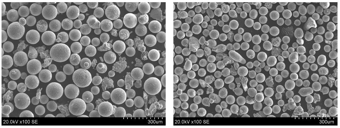
Titanium Alloy Powder
Geometry Description
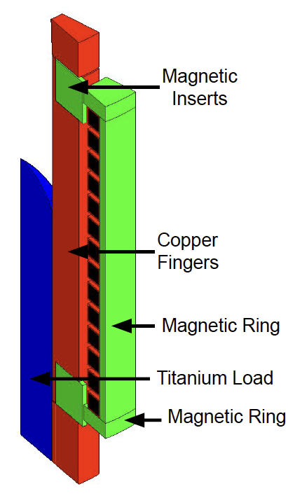
Mold and Billet Geometry
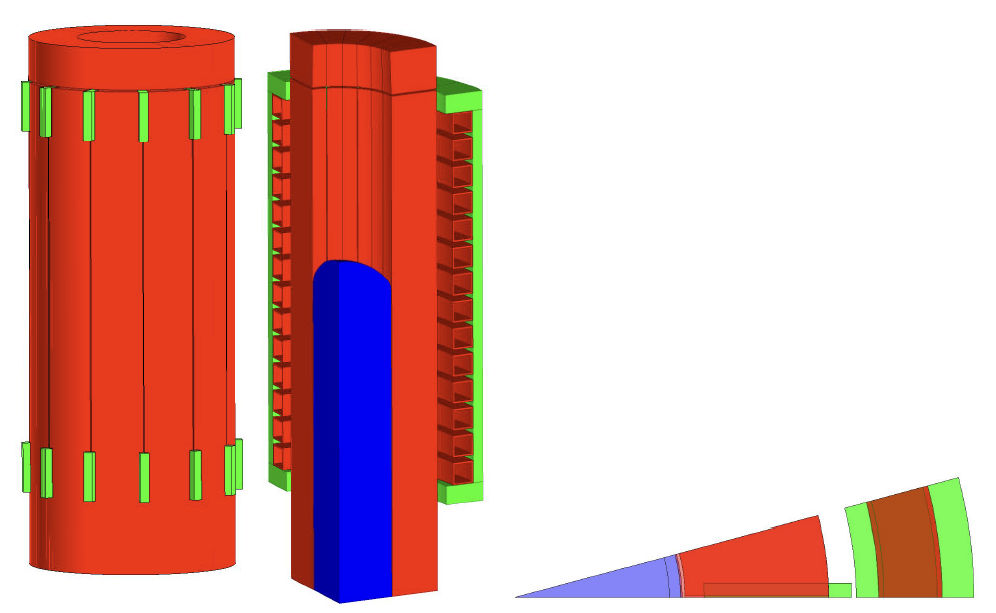
- 68mm ID
- 125mm OD
- 12 fingers and slits
- Uses soft magnetic composite inserts
- Has variable height for the study
Simulation Description
Flux 3D FEM software was used for the simulation
- 3D geometry was used
- Electromagnetic and thermal physics were used
- 1725°C maximum temperature was targeted
- Phase transformation not considered
- Assumed shape and top of billet position
- Fluxtrol 100 soft magnetic composite was used for the magntic inserts, rings, and shunts
- 1/24th of the geometry was modelled using symmetry planes
Insert/Coil Height Study
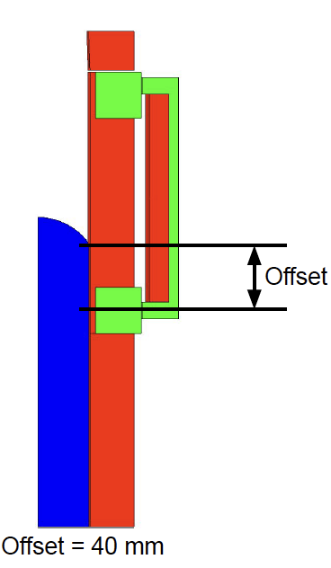
The coil height and was modified to change the length of the melt zone in the load. The bottom insert was moved with the bottom of the coil. A parameter ‘Offset’ was introduced to vary the coil height and bottom insert location.
‘Offset’ is defined by distance between the center of the bottom insert and bottom shunt and the top of the melt OD.
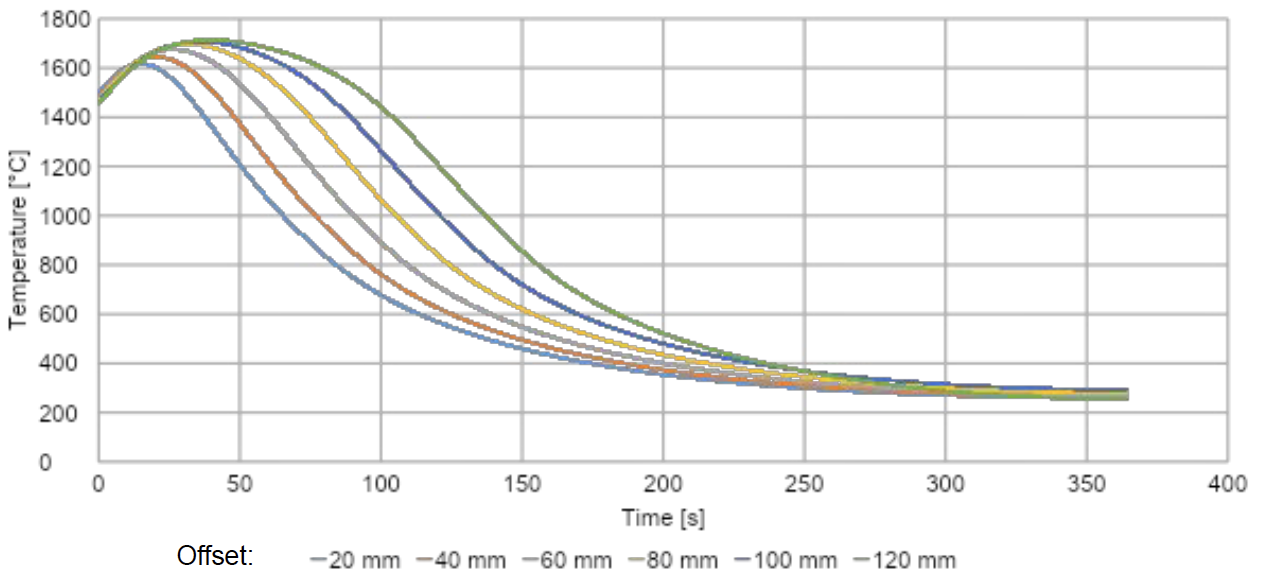
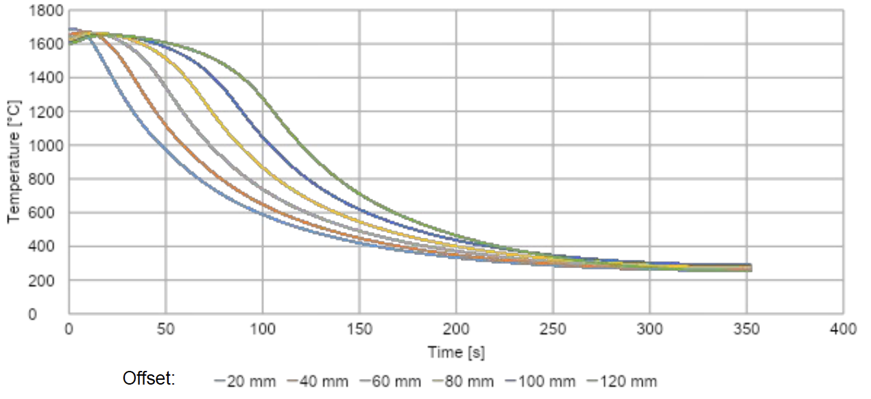
Offset values of 20, 40, 60, 80, 100, 120 mm were used. 120 mm is the original location.
Note: geometry was configured so that below the insert the mold is closed, not slotted.
The coil was changed to a single turn coil for faster solve times.
Initial and Boundary Conditions
The highlighted faces had thermal boundary conditions applied as such: radiation heat transfer using emissivity of 0.75, while convection wasn't added due to vacuum conditions. Conduction to the mold was not considered for this project.
Simulation parameters and goals.
Since steady state temperature is the goal of the investigation, the
billet was started at a uniform 1600°C and a maximum temperature
of 1725°C was targeted. The simulations were run for 3600s.
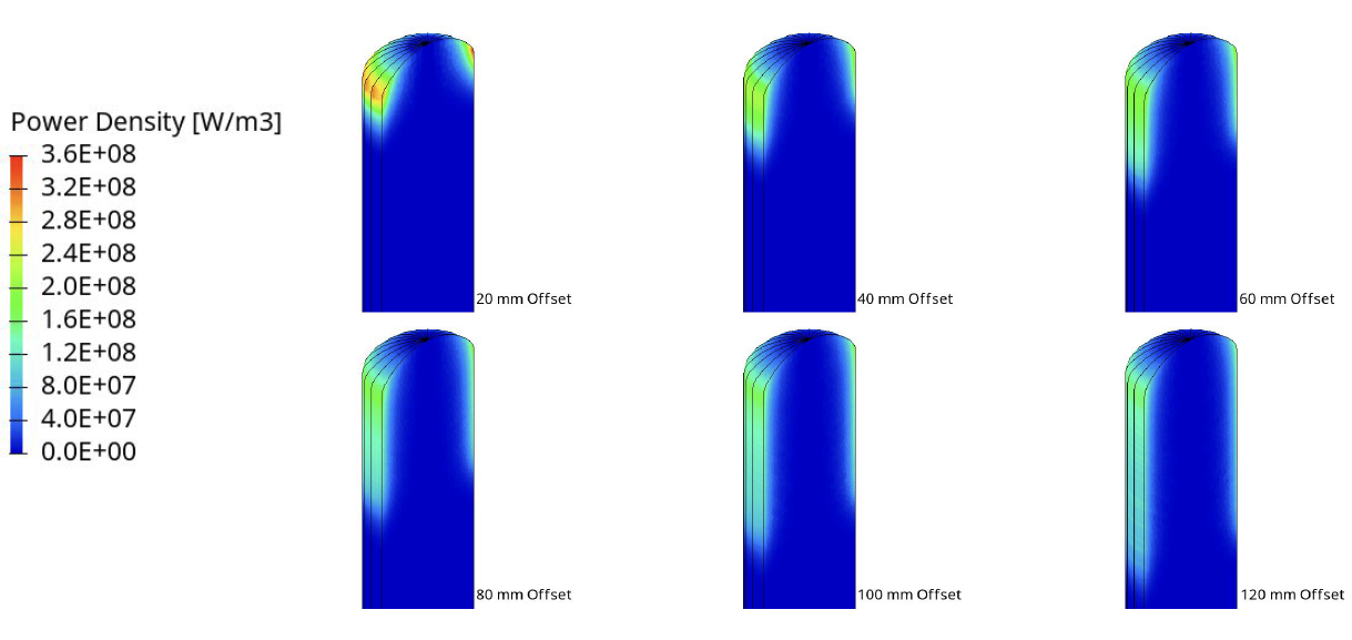
Power Density Results
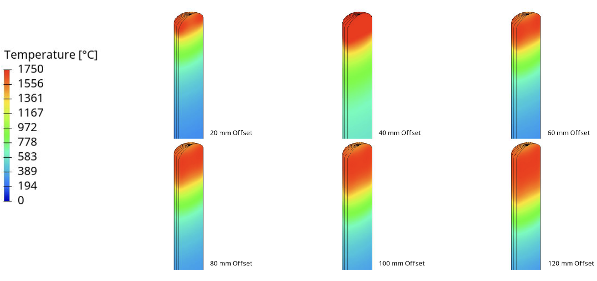
Temperature Results
Temperature Curves
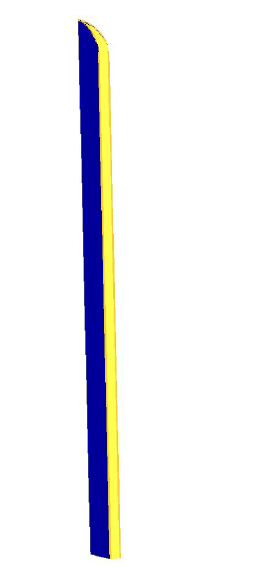
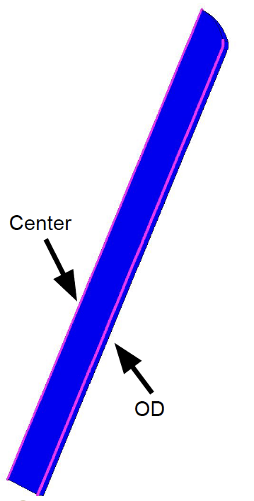
The two lines shown in the picture (OD and Center) were used to plot the temperature along the length of the billet.
From the withdraw rate of 1kg/min, the size of the billet (34.2 cm3 cross-section), and the axial temperature distribution, the temperature vs time data was calculated as follows:

This calculation converts the temperature profile of a static model to a moving temperature profile to better reflect material movement, as seen in actual systems.
Center Temperature vs Time
OD Temperature vs Time
Grain Structure Examples
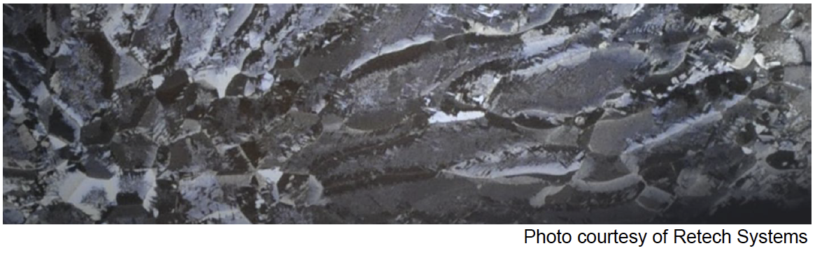
- Ti 6Al 4V shown in the picture is equiaxed in the center but columnar at the outer edges.
- The TNM alloy microstructure as-cast is equiaxed rather than columnar
- Area of future study
As Cast Ingot Examples
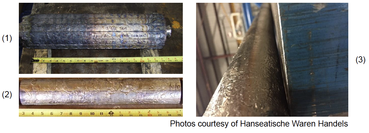
- 127mm diameter titanium aluminide (TNM) ingot produced by cold wall induction ingot withdrawal. Inserts were not used.
- 53mm diameter titanium aluminide (TNM) ingot produced by cold wall induction ingot withdrawal. Inserts, top and bottom rings, and coil shunts were used.
- 53mm diameter titanium aluminide (TNM) ingot – same as #2, shown along the axis of the ingot.
Conclusions
- 3D simulations were made to predict temperature profiles in titanium and
titanium alloy billets in billet casters
- Static temperature profiles were converted to dynamic temperature profiles
- Simulations were made for different coil heights and offsets
- Results show increasing the offset between the bottom of the coil and inserts, relative to the top of the billet, results in less rapid loss of temperature in the billet
- The simulations considered an existing mold design, further optimization can be used to modify the temperature profile
- Future work will focus on experimental testing to validate the simulation results
- Future work will also focus on correlating grain structure with temperature profiles
If you have more questions, require service or just need general information, we are here to help.
Our knowledgeable Customer Service team is available during business hours to answer your questions in regard to Fluxtrol product, pricing, ordering and other information. If you have technical questions about induction heating, material properties, our engineering and educational services, please contact our experts by phone, e-mail or mail.
Fluxtrol Inc.
1388 Atlantic Boulevard,
Auburn Hills, MI 48326
Telephone: +1-800-224-5522
Outside USA: 1-248-393-2000
FAX: +1-248-393-0277