


Authors: Sean M. Muyskens, Tareq I. Eddir, Robert C. Goldstein
Location/Venue: ASM HTS Heat Treat 2021 St. Louis, Missouri
This paper will revisit a case study originally done for ASM HTS Conference in 2009. The goal then was to solve an induction coil lifetime issue of an induction coil for heat treatment of an automotive wheel hub. At the time, computer simulation was beginning to allow for full virtual prototyping of heat treat applications as an alternative to experimental testing. While practical knowledge allowed for the successful determination of the cause of short coil life, and iterative simulation led to implementation of a longer lasting coil that met the required pattern, simulation was not used at the time to pinpoint the cause of failure. As faster computing becomes more widely available and finite element analysis (FEA) improves in scope and accuracy, virtual prototyping and detection of these failure modes are becoming faster and lower cost options compared to the traditional test and trial method. To highlight the leaps made in virtual prototyping, this case study that was previously done as an axisymmetric 2D model will be done in 3D electromagnetic plus thermal with rotation for the full part.
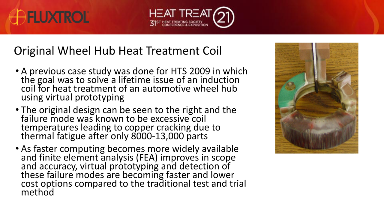
A previous case study was done for HTS 2009 in which the goal was to solve a lifetime issue of an induction coil for heat treatment of an automotive wheel hub. The failure mode was known to be excessive coil temperatures leading to leading to copper cracking due to thermal fatigue. Virtual prototyping was used to redesign the coil to maintain an acceptable pattern with low coil copper temperatures to extend coil lifetime.
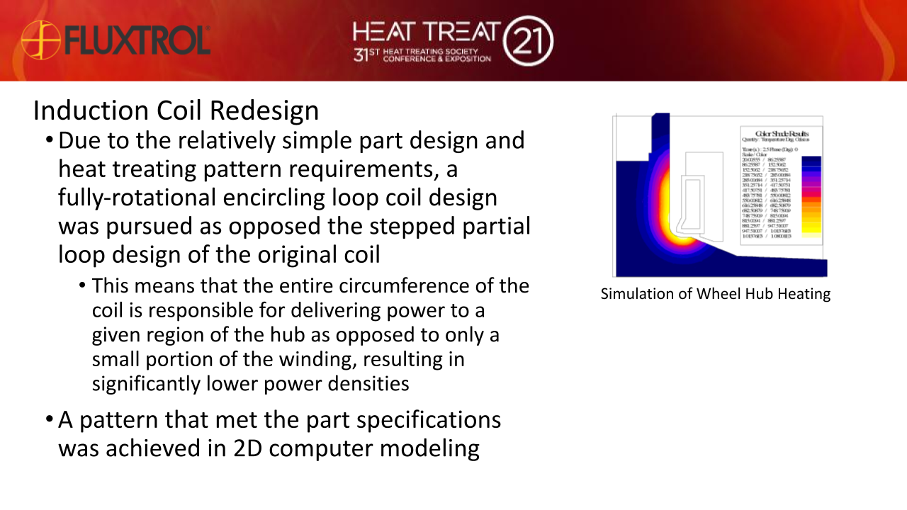
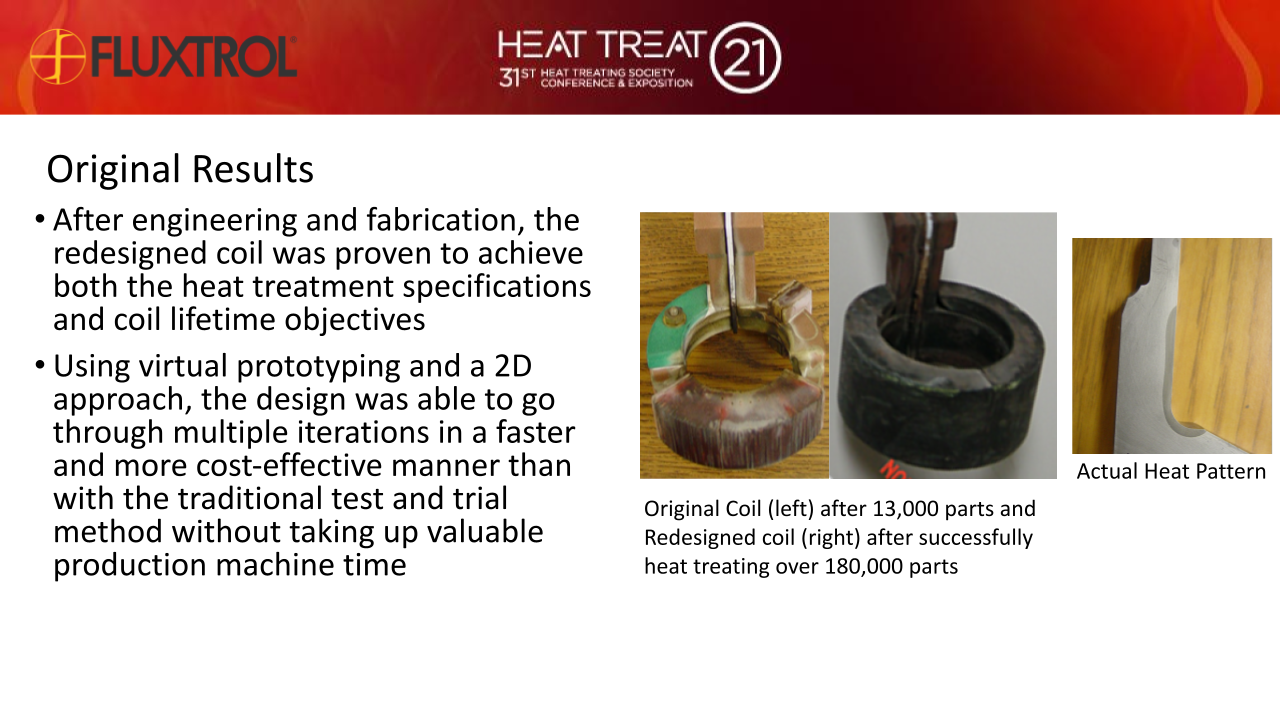
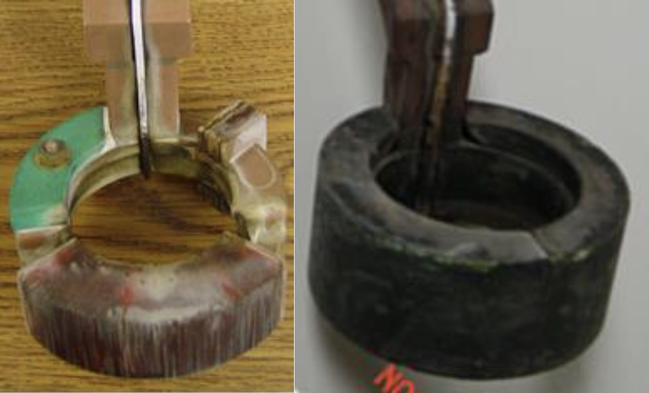
Due to the relatively simple part design and heat treating pattern requirements, it was possible to design a new coil with rotational symmetry, allowing for study of this design using 2D software. This new coil proved successful, and both the original and redesigned coils can be seen in Fig. 1. The results of computer simulation showed excellent agreement with those achieved on the real machine in terms of heat treatment pattern. The lifetime of the new induction coil was more than 10 times that of its predecessor [1].
The more general conclusions about the cost-effective application of virtual prototyping over experimental testing are still true today. Now, with the added benefit of improved simulation capabilities seen over the last decade, more complicated parts and coils can be modeled not only to investigate optimal conditions for heating of the part, but also lowering coil temperatures to improve coil lifetimes [2,3]. This paper will simulate the redesigned coil in 3D and compare part heating and coil thermals to observed results.
Over the last decade as 64-bit systems replaced 32-bit ones, the availability, speed and amount of computing power, RAM and storage space as well as the ability of the software to utilize it has increased dramatically. 3D simulation is becoming more accessible and cost effective for use in virtual prototyping. While 3D simulation is not required or recommended for every application, for example the redesigned coil is approximated very well in 2D, there are certain cases in which it is necessary.
With this expansion of 3D capabilities come many benefits to virtual prototyping as a cost-effective alternative to the trial and error method of coil design:
The goal of this paper is to show the ability to model both the part heating and the induction coil temperatures in a 3D coupled rotational model.
3D simulation may have come a long way in the past decade, but the stages of development for an induction heat treating process using virtual prototyping have not changed much. For a new component, the steps for virtual prototype development may include:
In many instances, a machine exists already or the part is very similar to something already done and this process may be reduced.
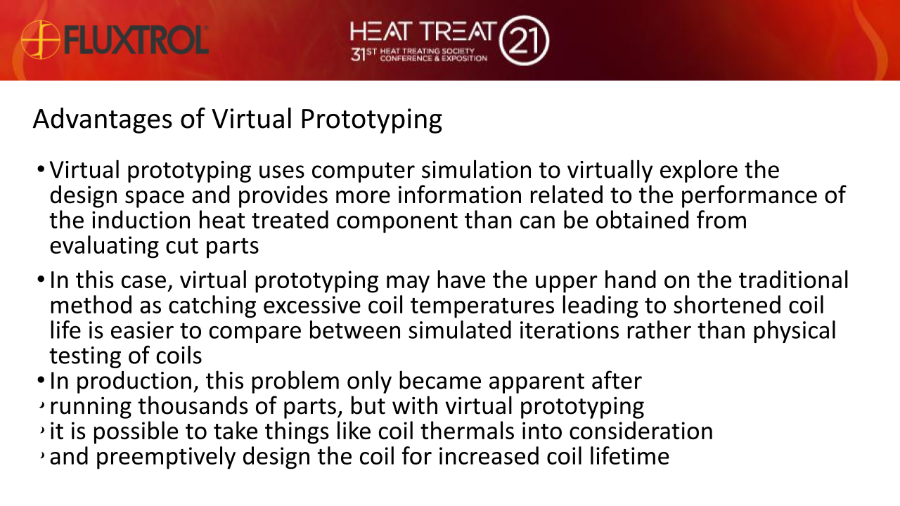
Many of the steps involved are the same as in the case of a traditional empirical development. The main differences are steps 2, 3 and 6. The traditional method utilizes simple hand calculations, tables and part history records to determine the preliminary process design. There is no step 3 in the empirical method and as a result history and data from experimental tests are the only information available for coil modification. To contrast the two methods, virtual prototyping uses computer simulation to virtually explore the design space and provides more information related to the performance of the induction heat treated component than can be obtained from evaluating cut parts. For those who use statistical methods, it is possible to run DOE trials on the computer instead of with real parts to analyze sensitivity to material composition, incoming material structure, part dimensions, etc.
Up until recently, temperature distributions were used for estimating case depths in the majority of coils and processes designed by computer simulation. Due to continued improvements in computer hardware, software, and material databases it is now practical to model resulting microstructures and residual stress profiles by coupling a metallurgical, stress and dimensional movement tool in the software with the heating and cooling results [4,5].
We can expect to see continued expansion of virtual tools to replace physical tests in induction heat treating process development. Other available capabilities with simulation software that were not used in this study include the effect of upstream operations on incoming properties (casting, forging, heat treating, machining, etc.) and downstream operations (machining, tempering, coating, shot peening, etc.) on final component performance. For instance, in 2016 a study was done on bi-material billets using coupled Flux 2D™ and DANTE® for simulation of induction heating and dimensional movement of the part [5]. It was noted that moving forwards, the results of the Flux2D™ and DANTE® software models should be coupled with additional modeling packages for subsequent manufacturing steps. The Flux2D™ induction heating results were used as an input for Dante simulations, including residual stresses and dimensional movement due to metallurgical transformations during induction hardening and subsequent furnace tempering and mechanical loading to determine the component performance on the test stand.
In this case, virtual prototyping may have the upper hand on the traditional method as catching excessive coil temperatures leading to shortened coil life is easier to compare between simulated iterations rather than physical testing of coils. This problem only became apparent after running thousands of parts, but with virtual prototyping it is possible to take things like coil thermals into consideration and preemptively design the coil for increased coil lifetime. And while it is not explored in this paper, coupling with other physics packages will also become more accessible in order to investigate stresses within the coil, as well as the metallurgical transformations and resulting residual stresses in the part.
A single-race steel wheel hub for a light duty truck was being induction heated for selective surface hardening. The process was single shot with rotation. The manufacturer was having problems with short inductor life, and unacceptable down time due to set-ups. The inductor was failing after only 8,000-13,000 parts. 50,000 parts per coil was the required amount to maintain the desired production volumes on the machine as changeovers typically resulted in approximately 4 hours of lost production. The induction coil they were using was developed through the traditional trial and error method. The resulting production coil was a multi-stepped single turn coil. Laminations and a piece of Fluxtrol A were installed on select regions of the coil to provide the required pattern (Fig. 2).
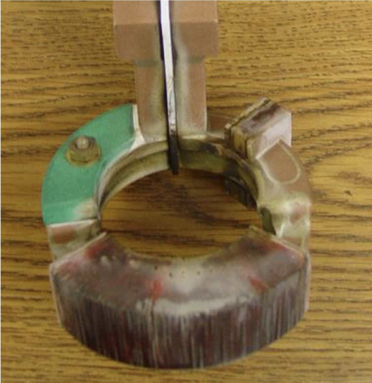
An examination of a failed coil showed that copper cracking occurred directly under the long section of laminations due to stresses most likely caused by thermal cycling. It is expected that this area under the laminations reached the highest temperatures during the heating cycle. Degradation of the laminations also occurred but was not the reason the coil was taken out of production.
As the failure mode was known to be caused by higher temperatures in the coil, a focus was made on achieving the desired heat pattern while reducing the localized power densities in the induction coil winding. After the initial iterations in 2D, the design in Fig. 3 was created to replace the original coil during the original study. The goal was to maintain the heat treating pattern and achieve a minimum of 50,000 heated parts per coil. This goal was achieved, and this design lasted more than 10X longer than the original coil [1].
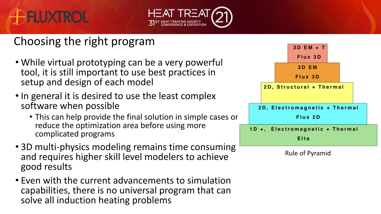
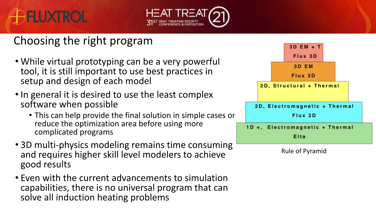
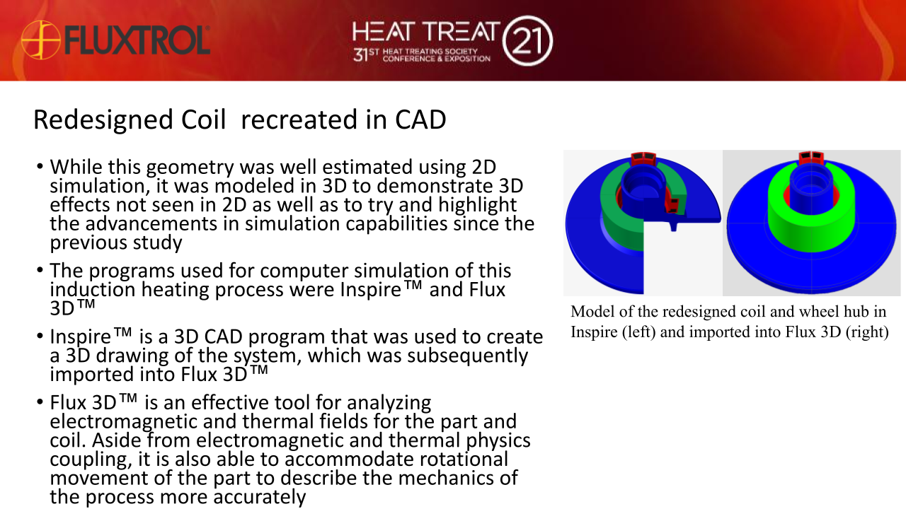
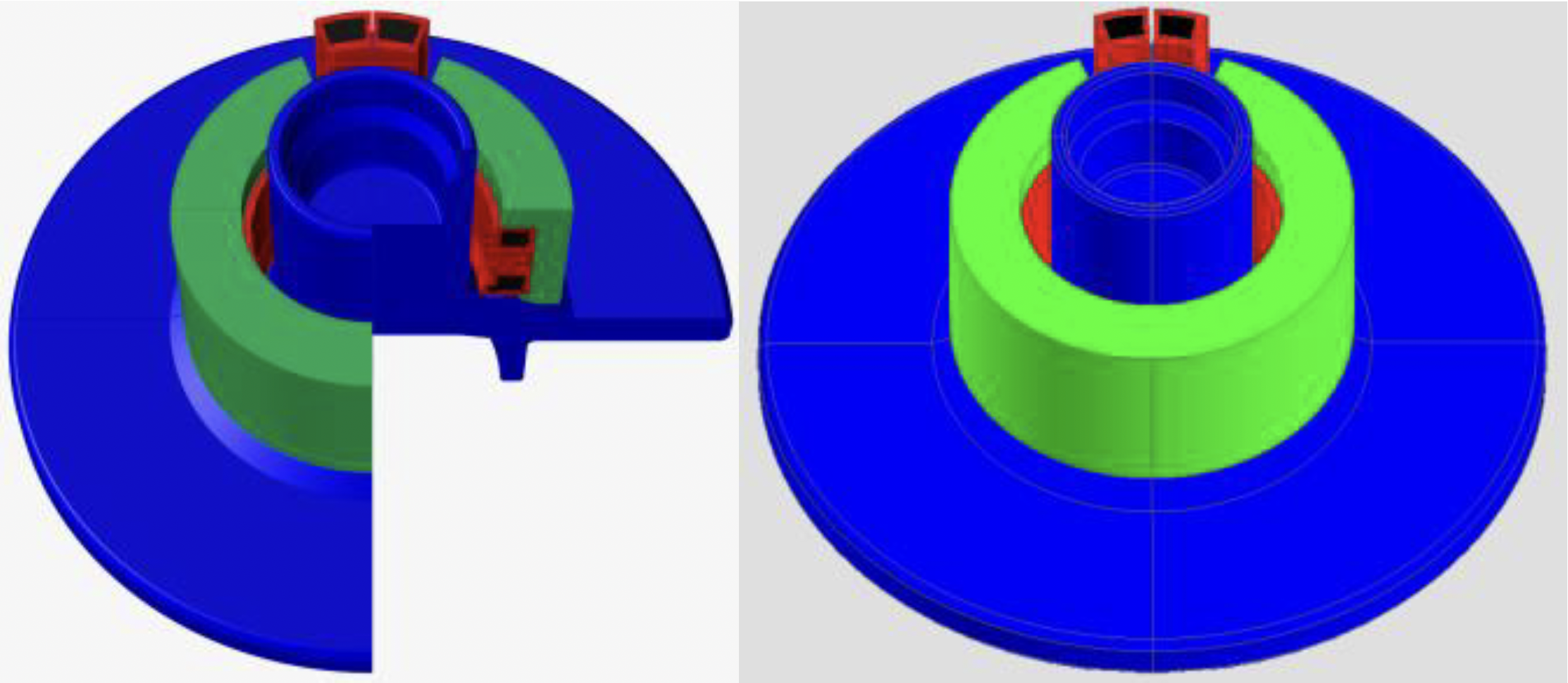
While this geometry was well estimated using 2D simulation, it was modeled in 3D to demonstrate 3D effects not seen in 2D as well as to try and highlight the advancements in simulation capabilities since the previous study. The programs used for computer simulation of this induction heating process were Inspire™ and Flux 3D™. Inspire™ is a 3D CAD program that was used to create a 3D drawing of the system, which was subsequently imported into Flux 3D™. Flux 3D™ is an effective tool for analyzing electromagnetic and thermal fields for the part and coil. Aside from electromagnetic and thermal physics coupling, it is also able to accommodate rotational movement of the part to describe the mechanics of the process more accurately. A ¾ view of the redesigned coil and wheel hub as drawn in Inspire and full view imported into Flux 3D and can be seen in Fig. 4.
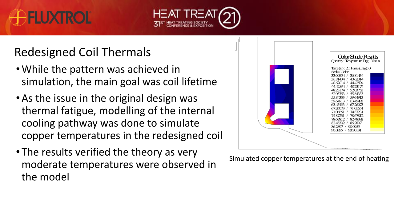
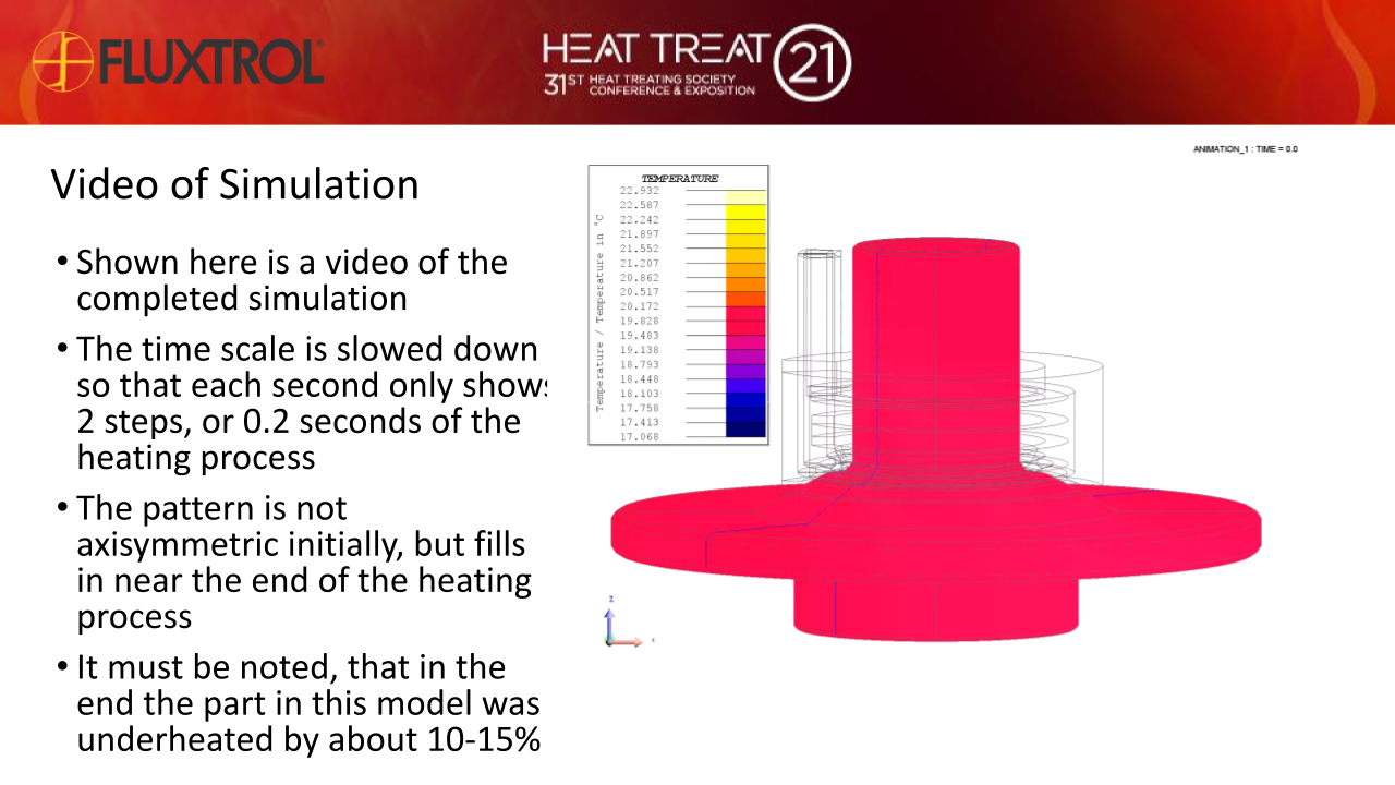
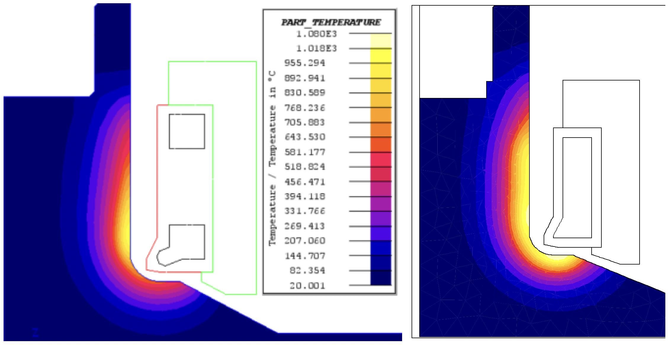
After reproducing the geometry, the mechanical, electromagnetic and thermal parameters of the system were defined in Flux 3D. While the rotational speed of the wheel hub would be much higher in the actual process, to ensure a whole number of rotations and even power distribution during the 2.5 second heat time, the rotation was set to 72 RPM. The frequency was set to 20kHz and the current was altered until the proper temperature distribution in the wheel hub was achieved to obtain the desired hardening pattern. The magnetic properties for the Fluxtrol A were set. Heat transfer boundaries were assigned to allow for radiation and natural convection on the outer faces of the wheel hub and coil, as well as for forced convection withing the water circuit of the coil. Unfortunately, due to time constraints the exact power required to reach the desired heating pattern in the Wheel Hub was not reached. Additional work is ongoing to accurately model the real process. Below Fig. 5 shows the temperatures evolved in the coil at the end of the heat cycle for the underheated 3D simulation compared to those found in the original 2D study.
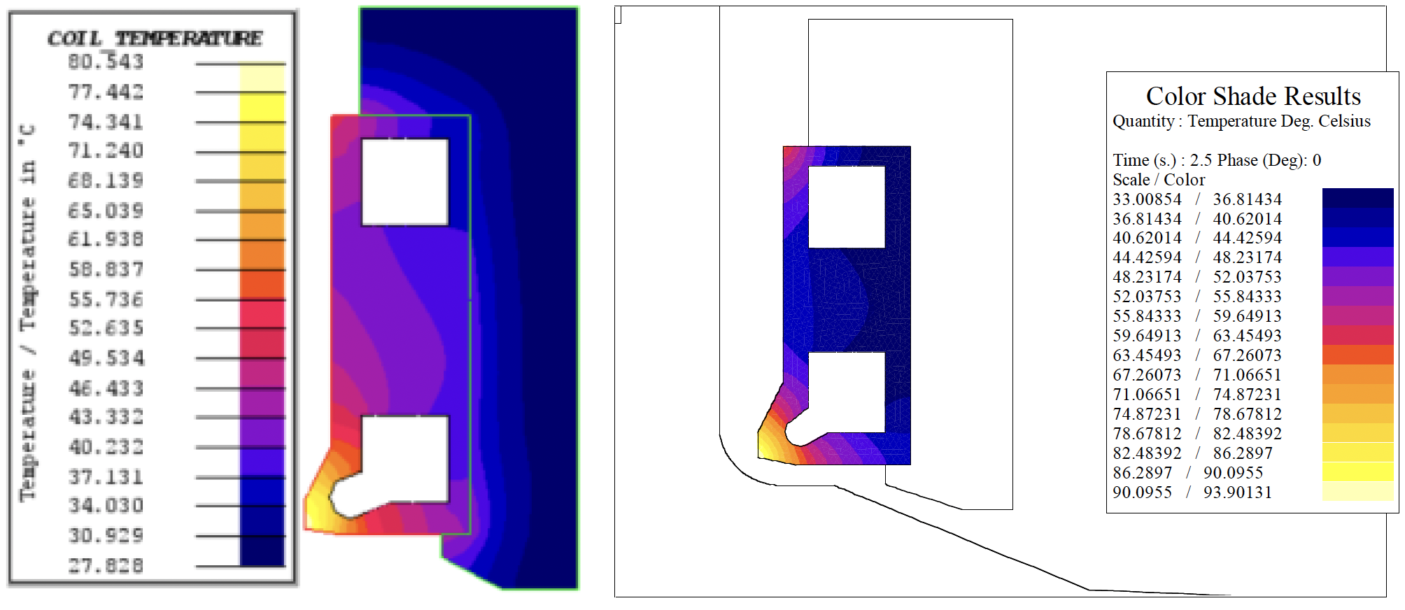
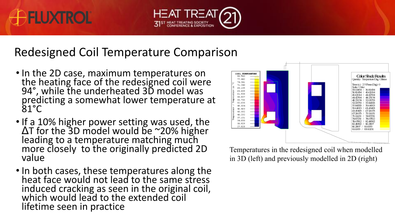
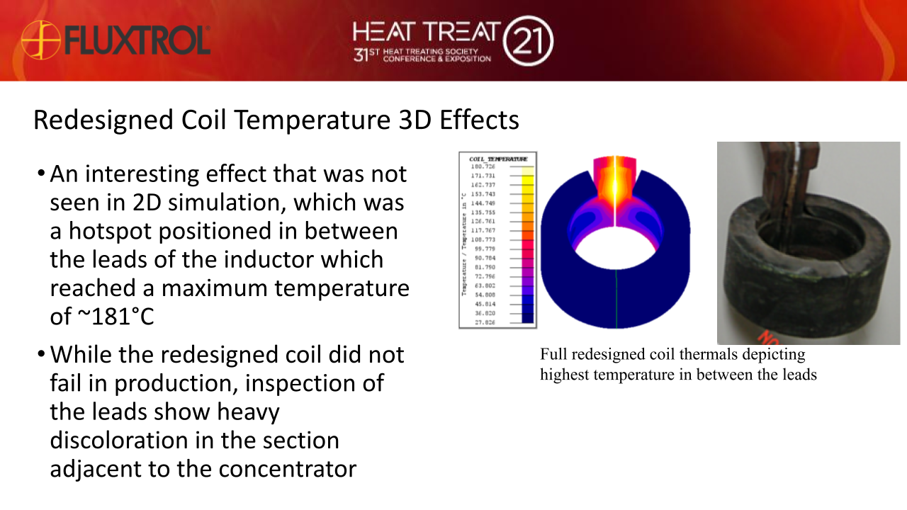
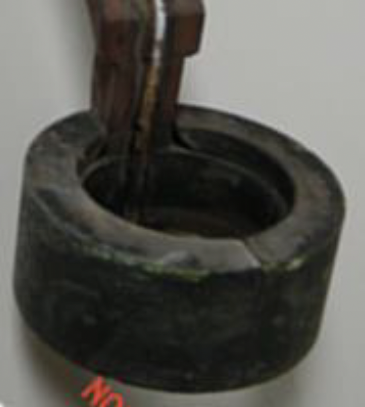
In the 2D case, maximum temperatures on the heating face of the redesigned coil were 94°, while the underheated 3D model only got up to 81°. While the exact temperatures do not match up, the overall pattern with the nose of the coil being the hotspot and the top corner being the next hottest does. Once the model is run again with a higher current, these will match up more closely. These temperatures along the heat face would not lead to the same stress induced cracking as seen in the original coil, which would lead to the extended coil lifetime. Aside from the heat face, there is one interesting effect that was not seen in 2D simulation, which was the hotspot positioned in between the leads of the inductor. While the redesigned coil did not fail in production, inspection of the leads in Fig. 3 show heavy discoloration in the section adjacent to the concentrator. This matches the position of the simulated maximum temperature in the leads seen below in Fig. 6.
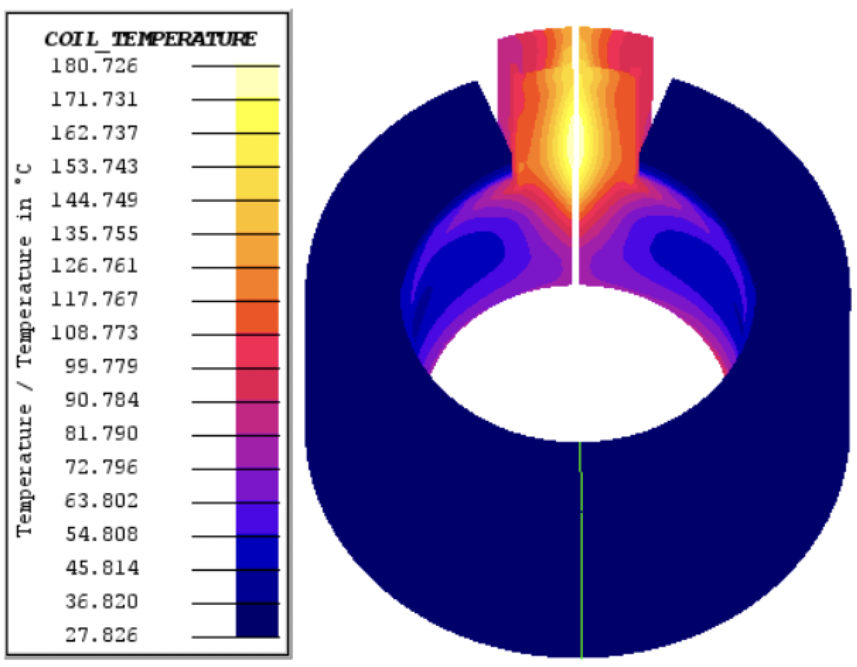
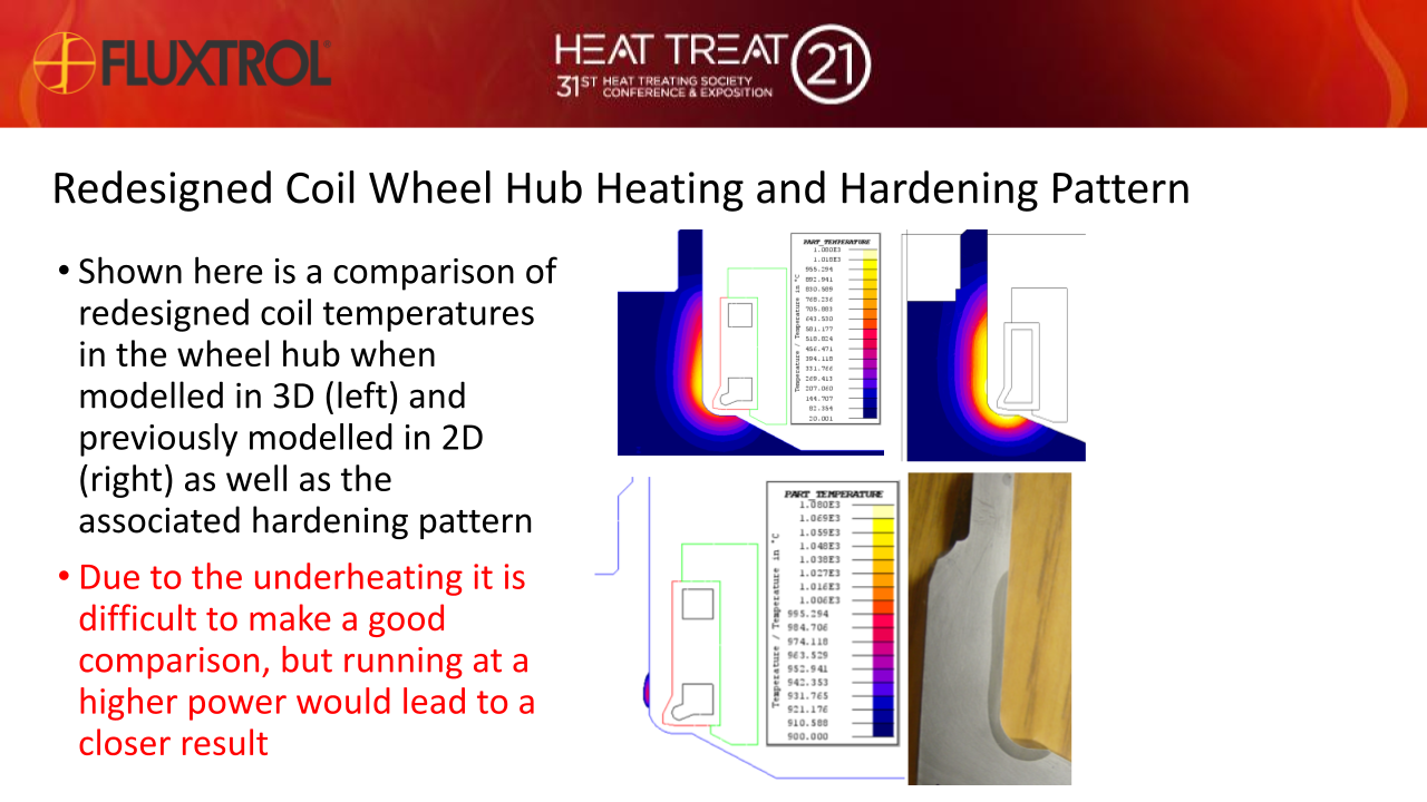
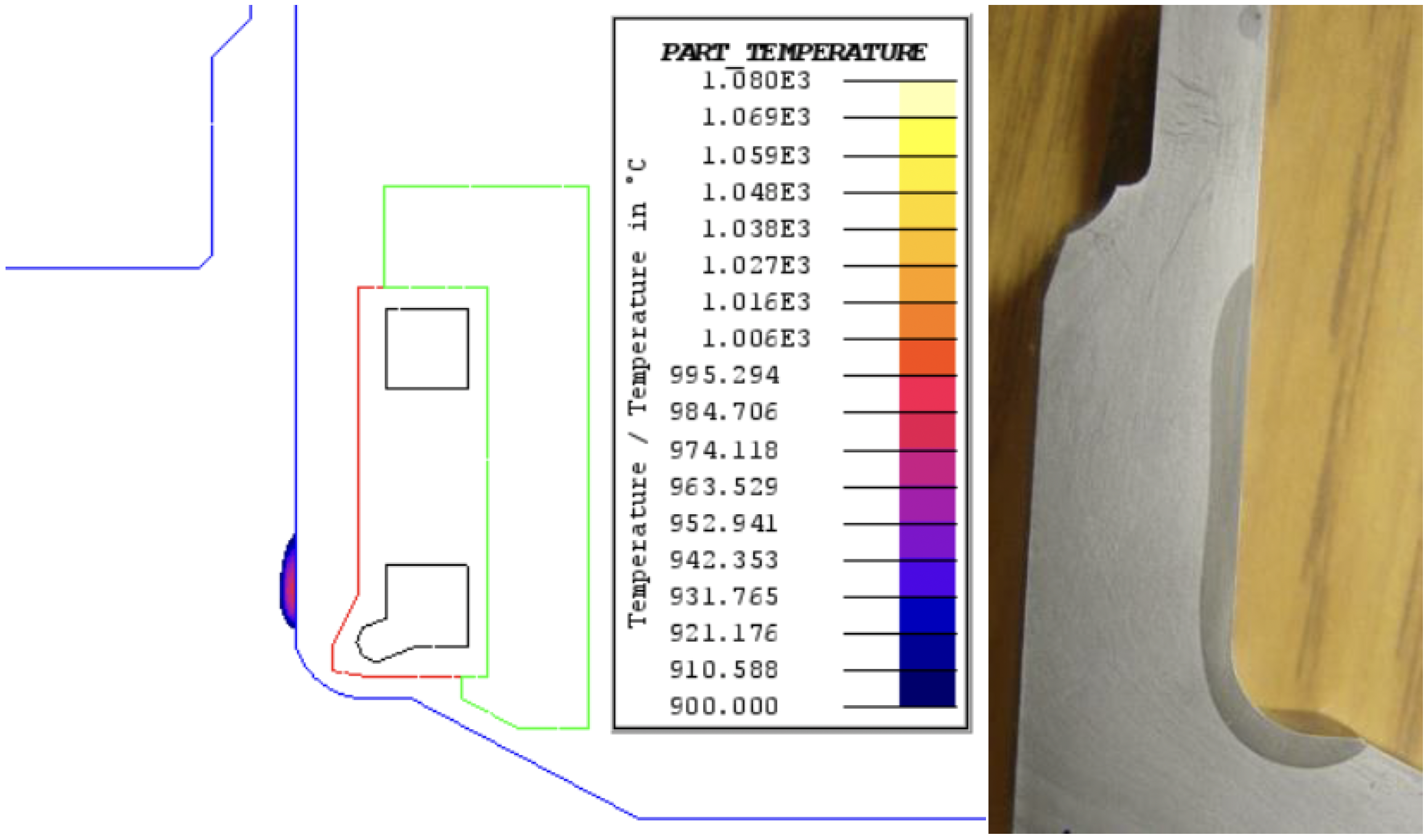
This design met the lifetime requirement and as can be seen in Figs. 7 and 8 it is also beginning to match the heat pattern as previously simulated in 2D. Again, the model is underheated and future work is planned to run this again at a higher power to better match the 2D results. This means coil head powers are lower than those required in the real system and that coil temperatures are being underestimated; however, considering an approximately 6% higher power is required, coil temperatures in this 3D model should be very close to the temperatures originally predicted in 2D.
As faster computing becomes more widely available and finite element analysis (FEA) improves in scope and accuracy, virtual prototyping and detection of these failure modes are becoming faster and lower cost options compared to the traditional test and trial method. To highlight the leaps made in virtual prototyping, this case study that was previously done as an axisymmetric 2D model will be done in 3D with rotation for the full part. While 3D simulation may not be strictly necessary in this case, as was demonstrated by the good correlation between 3D and previous 2D results, it can allow for a more accurate depiction of the process provided sufficient time for setup and solving of the scenario. Even with the limited results shone in this paper the 3D model pointed towards the next potential coil lifetime issue that could arise in between the leads. Virtual prototyping in 3D allows for more informed design and in the end led to a longer lasting coil.
Moving forward, the model of the redesigned coil will be run at the higher power required to match the heat treatment pattern, and models of the original coil will be run to pinpoint the cause of failure leading to shortened coil lifetime. In addition to electromagnetic and thermal models, it is desired to add additional physics packages to study this process further. Looking at the dimensional movement of the part and analyzing the sources of stress that lead to the observed cracking would demonstrate the benefits of virtual prototyping for existing processes.
[1] Goldstein R., Nemkov V., Jackowski J., “Virtual Prototyping of Induction Heat Treating,” Proc 25th ASM International Heat Treating Society Conference and Exhibition, Indianapolis, IN, Sep. 2009.
[2] Goldstein R., Nemkov V., "Increasing Inductor Lifetime by Predicting Coil Copper Temperatures,” Proc 24th ASM International Heat Treating Society Conference and Exhibition, Detroit, MI, Oct. 2007.
[3] Svendsen H., Hagen S., “Thermo-Mechanical Fatigue Life Estimation of Induction Coils,” International Scientific Colloquium on Modeling of Electromagnetic Processing, Hannover, Germany, Oct. 2008
[4] Goldstein R., ASM Handbook Volume 4C, ASM International (USA, 2014), p 633-645
[5] Goldstein R., Chavdar B., Ferguson L., “Modeling of the Heating Sequences of Lightweight Steel/Aluminum Bimaterial Billets for Hot Forging and Hot Hydroforging,” Proc 23rd IFHTSE Congress, Savannah, GA, Apr. 2016.
[6] Li Z., Fett G., Nemkov V., “Modeling Stress and Distortion of Full-Float Truck Axle During Induction Hardening Process,” Thermal Processing, Apr. 2015.
Our knowledgeable Customer Service team is available during business hours to answer your questions in regard to Fluxtrol product, pricing, ordering and other information. If you have technical questions about induction heating, material properties, our engineering and educational services, please contact our experts by phone, e-mail or mail.
Fluxtrol Inc.
1388 Atlantic Boulevard,
Auburn Hills, MI 48326
Telephone: +1-800-224-5522
Outside USA: 1-248-393-2000
FAX: +1-248-393-0277